Loading ...
Loading ...
Loading ...
Installation
A Class HP Installation a
nd User Instructions R02583
-6 09/15
Page
21
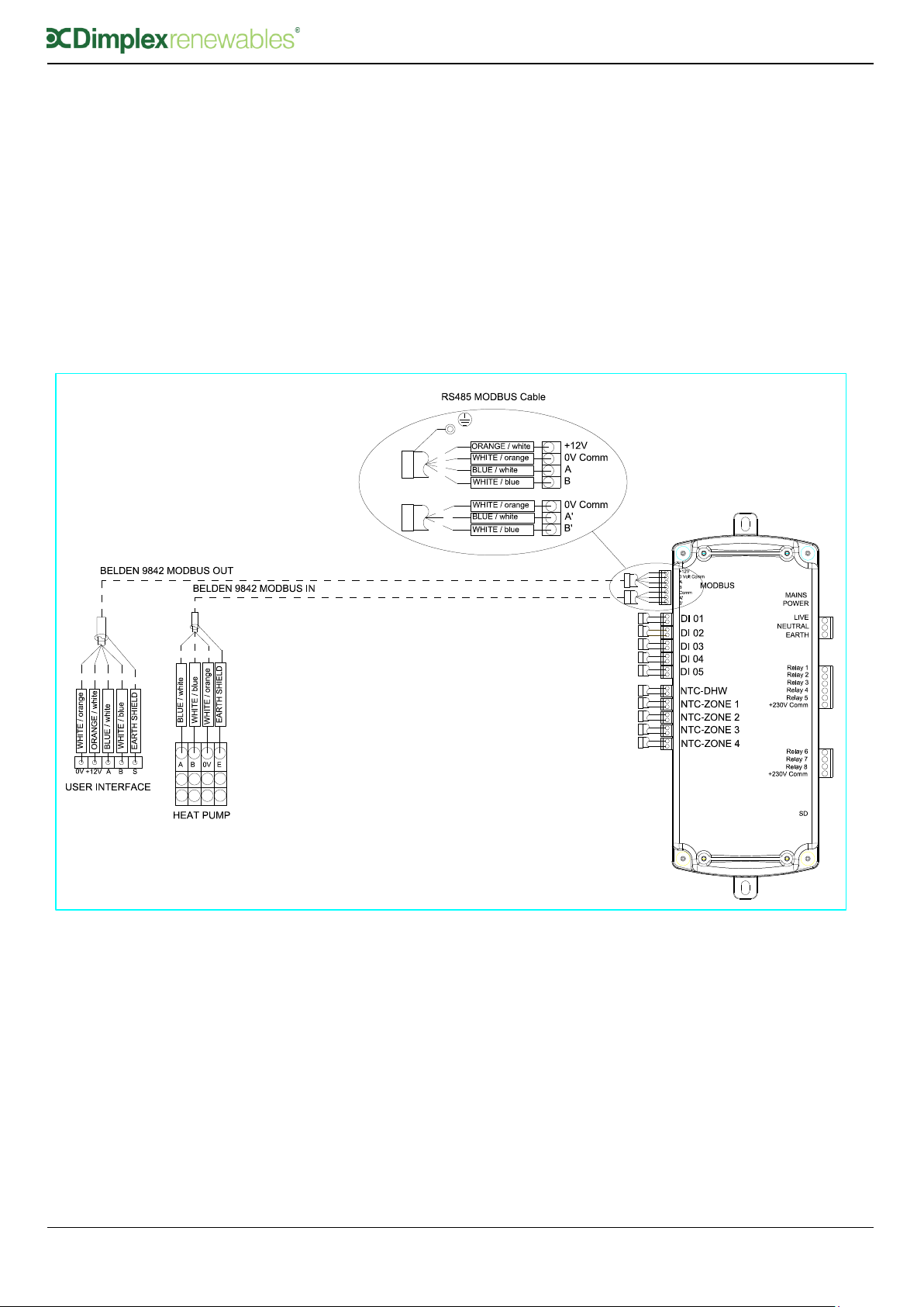
5.9.2 Modbus Connection
Correct installation of the Modbus connections
is critical for communication between the heat
pump, UI and the cylinder. Figure 9 illustrates
how these connections must be made. The
modbus wire must be specified to BELDEN 9842.
The maximum allowable network length is
100m.
Modbus in connection comes from the heat
pump master controller.
Modbus out connection goes to the user
interface.
The earth shield of the Modbus connection
must be connected to ground at both ends.
The Earth connector block or the cylinder
stat bracket can be used as a ground
connection.
The Modbus cables can be fed inside the
low voltage trunking (LHR) under the metal
hood and clamped to the strain relief bar,
using the supplied cable ties.
Note: The earth shield in the cable from
the heat pump to the cylinder is only
terminated at the cylinder.
Figure 9: Modbus Communication Connections
5.9.3 Zone Connections
For a dual zone system, i.e. DHW and CH, a
pump and a three port valve is required;
these are included in the scope of delivery
of the heat pump hydraulic pack.
Where additional zones are required, the
installer must specify and source suitable
components. Figure 10, illustrates wiring of
each pump and/or zone valve for up to 4
zones.
Note: The water module PCB is only
capable of switching valves and under no
circumstances should ERP pumps be
switched, as irreparable damage will be
caused that will void the warranty.
Loading ...
Loading ...
Loading ...