Loading ...
Loading ...
Loading ...
Installation
A Class HP Installation a
nd User Instructions R02583
-6 09/15
Page
15
5.6 Coil Return Connections
If the return connection is the lowest point in
the heat pump loop, a suitable drain device
should be installed. For location of connections
see Figure 1 and see Figure 2 for solar cylinder
connections.
It is recommended that the fittings used to
connect to the cylinder are suitable for stainless
steel, the flow and return should use 28mm
compression fittings. Not all push fit fittings can
be used – please check with your supplier.
When using compression fittings, ensure that
the connection is not over-tightened.
For ease of maintenance it is recommended to
install a drain valve (supplied) at the return
connection of the solar coil. Compression
fittings should be used to complete this part of
the installation.
Note: If the cylinder is located higher than
the solar collector array, a two port valve
has to be installed and wired accordingly.
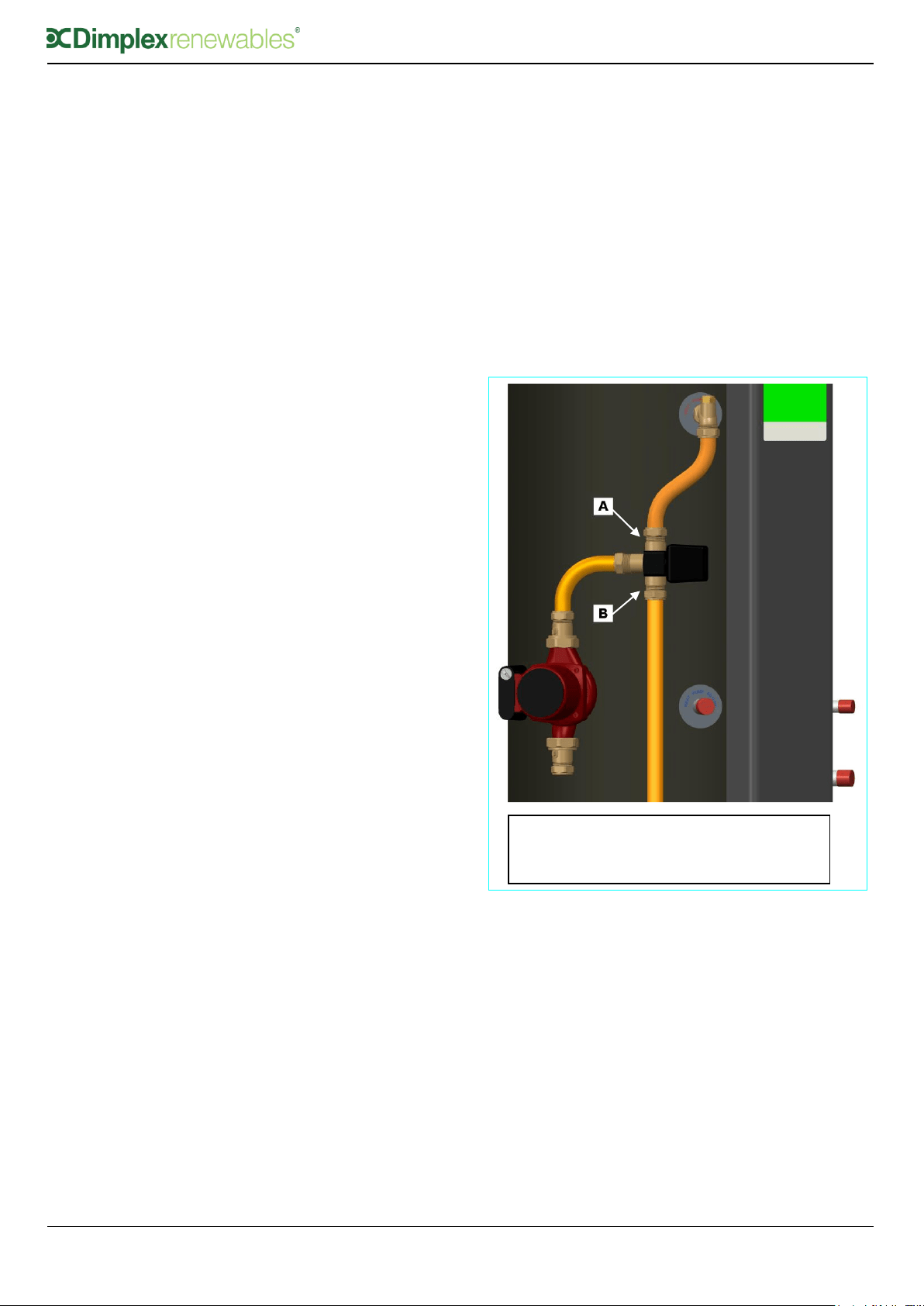
5.7 Coil Flow Connections
If the flow connection is the highest point in the
heat pump loop and if the system was not
commissioned using a flush and fill pump, an
adequate device for de-aeration must be
installed. The coil flow connection must be
connected to the A connection of the three port
valve. See Figure 6.
Note: Special care is required when fitting
the 3 port valve to ensure “A” goes to the
DHW coil and that “B” goes to the buffer.
This is different to the normal convention
that may be used.
Figure 6: Diagram Showing Positions of Valve
Legend:-
A = HP Flow
B = HP Flow to Buffer
Loading ...
Loading ...
Loading ...