Loading ...
Loading ...
Loading ...
Pre-Installation
A Class HP Installation a
nd User Instructions R02583
-6 09/15
Page
10
CLEANING INSTRUCTIONS: Clean outer
cladding of cylinder with a soft cloth
dampened with warm water only. Do
not use abrasive or aggressive
cleaning materials, such as alcohol or
petroleum based solvents, as this may
damage the surface of the product.
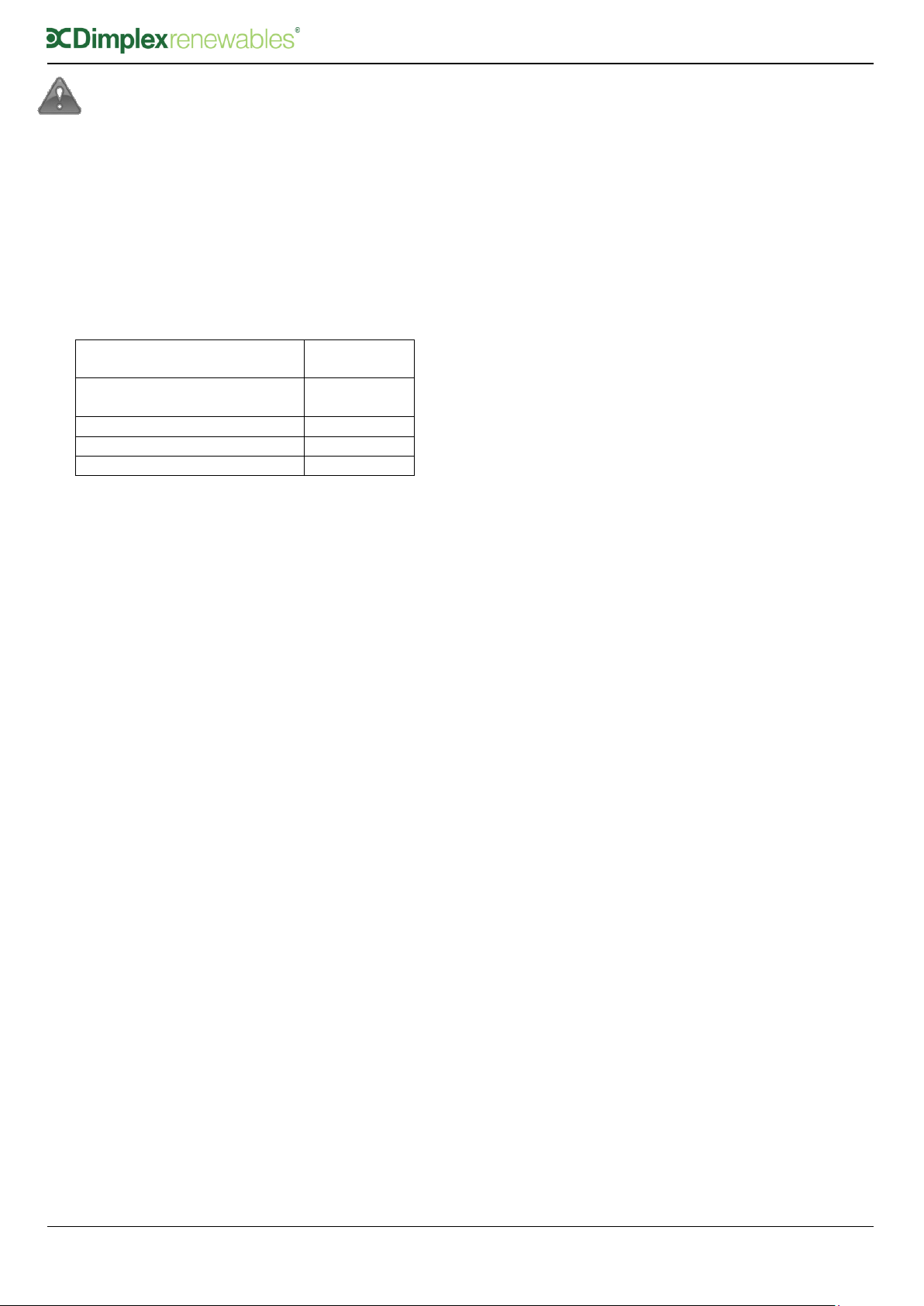
4.3 Cold Water Supply
For satisfactory and safe performance of the
unvented cylinder the water supply must meet
the following criteria:
Minimum dynamic
pressure
150 kPa
(1.5 bar)
Maximum inlet supply
pressure
1200 kPa
(12 bar)
Minimum flow rate
15 l/min
Max. chlorine content
250mg/L
Max. water hardness
200mg/L
The following instructions have to be followed
when installing the cold water mains supply to
the cylinder:
The cold water supply to the cylinder must
come directly from the cold water mains
after the mains stop valve to the property.
The cold water inlet pipe work should have
at least an inside diameter of 19mm and
should meet the requirements of the water
regulations for the supply of wholesome
water.
Dimplex recommend an annual maintenance
inspection is carried out on the domestic hot
water cylinder. In hard water areas this should
include inspection of the heat exchanger and
immersion heater, [above 120ppm or 120mg/l].
A local water treatment company should be
able to offer free water quality testing. The
heating elements may require periodic de-
scaling. The installer should do this as part of a
maintenance agreement.
If required, precautions can be taken to
minimise effects of water hardness, i.e.
installation of water conditioner or water
softener. These devices should be installed in
hard water areas where high water storage
temperatures are required, i.e. greater than
60°C storage temperatures, particularly when
water hardness exceeds 200ppm. Should the
water cylinder require de-scaling, this must be
performed by a qualified technician.
4.4 Building Regulation G3 Discharge
Requirements
As part of the requirements of Building
Regulation G3 any discharge from an unvented
system should be conveyed to where it is visible,
but will not cause danger to persons in or about
the building. The tundish and the discharge
pipes should be fitted in accordance with the
requirements of Building Regulation approved
document G3, (England and Wales), Part P of
Northern Ireland and Standard 4.9 of Scotland.
4.4.1 Discharge Pipe D2
The discharge pipe (D2) from the Tundish
should:
“have a vertical section of pipe at least
300mm long below the tundish before any
elbows or bends in the pipework and be
installed with a continuous fall of at least 1
in 200 thereafter.”
The discharge pipe (D2) should be made of:
“metal; or other material that has been
demonstrated to be capable of safely
withstanding temperatures of the water
discharged and is clearly and permanently
marked to identify the product and
performance standard.”
Dimplex strongly recommends the use of metal
pipework only and Dimplex does not take
responsibility for any damage caused from
discharges.
The discharge pipe d2 should be at least one
pipe size larger than the nominal outlet size of
the safety device unless its total equivalent
hydraulic resistance exceeds that of a straight
pipe 9m long, i.e. For discharge pipes between
9m and 18m the equivalent resistance length
should be at least two sizes larger than the
nominal outlet size of the safety device;
between 18 and 27m at least 3 sizes larger,
and so on; bends must be taken into account in
calculating the flow resistance. See Figure 3,
Table 2 and the worked example.
Note: An alternative approach for sizing
discharge pipes would be to follow Annex
D, section D.2 of BS 6700:2006 + A1:2009).
Loading ...
Loading ...
Loading ...