Loading ...
Loading ...
Loading ...
Installation
A Class HP Installation a
nd User Instructions R02583
-6 09/15
Page
20
5.9 Water Module Wiring
All wiring must be carried out by a suitably
qualified person and must be fully compliant
with the current release of Building & Wiring
Regulations. For general wiring configuration
see Figure 7.
The water module has been pre-wired to ensure
minimal additional work is required by the
installer. The following summarises the required
electrical connections which the installer must
make:
Primary connections, 5.9.1. A three core
cable must be connected between the
supply isolator and the cylinder connector
block. See Figure 8.
Modbus connection, 5.9.2. The
communication cable between the cylinder
and heat pump must be installed. See
Figure 9.
Zoned connections must be wired via the
cylinder PCB, i.e. circulation pumps and/or
zone valves, 5.9.3. See Figure 10.
Temperature sensors and digital inputs can
be connected to the PCB, 5.9.4 (DI 01-05),
(NTC-DHW and NTC-Zone 1-4). See Figure
11.
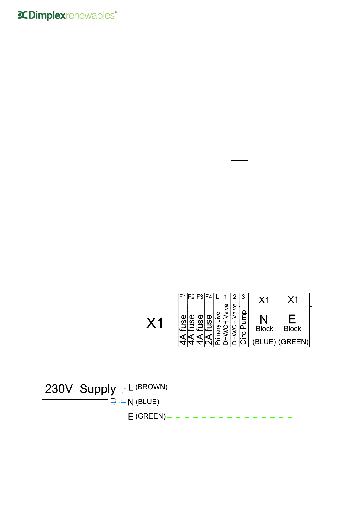
5.9.1 Primary Electrical Connections
In both retro fit and new build installations, a 3
core cable must be taken from the isolator
[typically a 16Amp double pole fused spur] and
connected to the primary connector block as
illustrated in Figure 8.
Live connection taken from a fused spur to
the cylinder connector block, [LHS grey
terminal].
Neutral and Earth wires must be connected
to the blue and green/yellow connectors
respectively, as per Figure 8.
Note: Solid core cable or ferruled multi
core cable must be used on the primary
connector block.
Figure 8: Primary Electrical Connections, Live, Neutral & Earth
Loading ...
Loading ...
Loading ...