Loading ...
Loading ...
Loading ...
English
16
TIPS: Before making or changing any connections, make sure that all the devices are disconnected
from the power outlet.
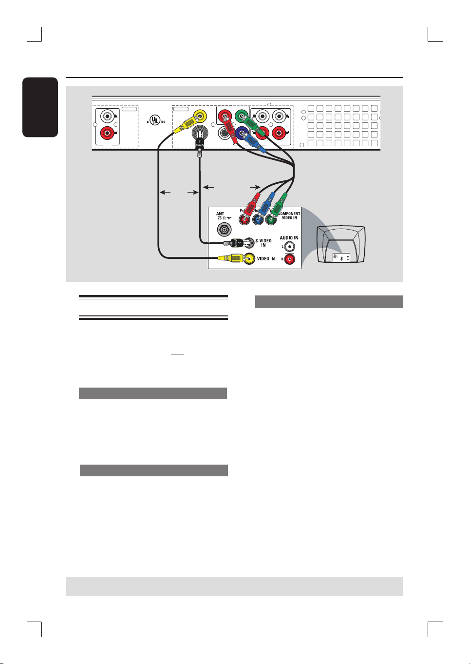
Step 1: Basic Recorder Connections (continued)
R
L
Y
P
B
P
R
COMPONENT
VIDEO
VIDEO
(
CVBS
)
S-VIDEO
(
Y/C
)
AUDIO
COAXIAL
R
L
R
L
OUT 3
(DIGITAL AUDIO)
INPUT
OUTPUT
OUT 2
OUT 1
DVD RECORDER 22F8
Complies with 21 CFR
1040.10 and 1040.11
R
LISTED
AUDIO
AU D IO
OUT
S-V ID E O
IN
VIDEO IN
TV
OR
Option 2
Option 3
OR
Option 1
Connecting the video cable
This connection enables you to view the
disc playback from the recorder.
You only need to choose one of the
options below to make your video
connection.
Option 1: Using Video (CVBS) jack
Use the supplied audio/video cables
(yellow plug) to connect the VIDEO
(CVBS)-OUT1 jack on the recorder to
the video input jack (or labeled as A/V In,
Video In or Composite) on the TV.
Option 2: Using S-Video jack
Use an S-video cable (not supplied) to
connect the S-VIDEO (Y/C) - OUT2
jack on the recorder to the S-Video input
jack (or labeled as Y/C or S-VHS) on
the TV.
Option 3 : Using Component Video
A
Use the component video cables (red/
blue/green - not supplied) to connect the
Y PB PR -OUT3 jacks on the recorder
to the corresponding component video
input jacks (or labeled as Y Pb/Cb Pr/Cr
or YUV) on the TV.
B
If your TV accepts Progressive Scan
signal, see the chapter “Setup Menu
Options – PREFERENCE settings” for
detailed set up.
IMPORTANT!
The progressive scan video quality is
only available through a Y PB PR
connection and a progressive TV is
required. It is strongly advised to
complete the recorder installation
rst, before enabling the
progressive scan feature.
Loading ...
Loading ...
Loading ...