Loading ...
Loading ...
Loading ...
Advice
CAUTION
To avoid considerable damage to the vehicle
electrical system, note the following careful-
ly:
●
If the jump leads are incorrectly connected,
this could result in a short circuit.
●
The vehicles must not touch each other,
otherwise electricity could flow as soon as
the positive terminals are connected.
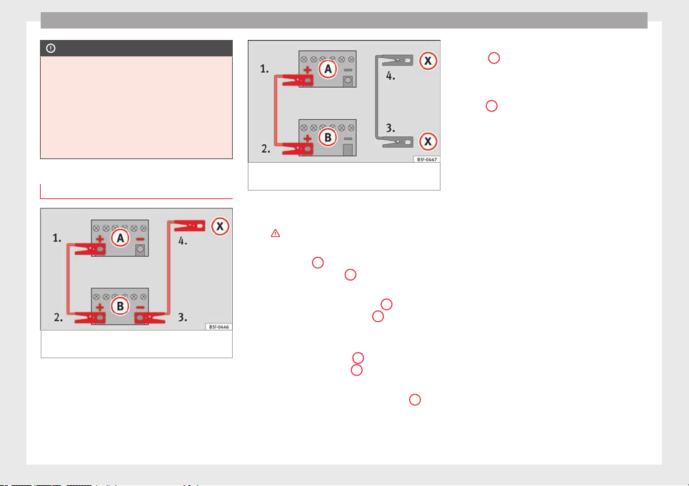
How to jump start: description
Fig. 133 Diagram of connections for vehicles
without Start-Stop system.
Fig. 134 Diagram of connections for vehicles
with Start-Stop system.
Jump lead terminal connections
1. Switch off the ignition of both vehicles
››› .
2. Connect one end of the red
jump lead to
the po
s
itive
+
terminal of the vehicle
with the flat battery
A
››› Fig. 133
.
3.
C
onnect the other end of the red jump
lead to the positive terminal
+
in the ve-
hicle providing assistance
B
.
4. For vehicles without Start-Stop system:
connect one end of the black jump lead to
the negative terminal
–
of the vehicle
providing the current
B
››› Fig. 133
.
–
F
or
vehicles with Start-Stop system: con-
nect one end of the black jump lead
X
to a
suitable ground terminal, to a solid piece of
metal in the engine block, or to the engine
block itself ››› Fig. 134
.
5.
C
onnect the other end of the black jump
lead
X
to a solid metal component bolted
to the engine block or to the engine block
itself of the vehicle with the flat battery.
Do not connect it to a point near the bat-
tery
A
.
6. Position the leads in such a way that they
cannot come into contact with any moving
parts in the engine compartment.
Starting
7. Start the engine of the vehicle with the
boosting battery and let it run at idling
speed.
8. Start the engine of the vehicle with the flat
battery and wait 2 or 3 minutes until the
engine is “running”.
Removing the jump leads
9. Before you remove the jump leads, switch
off the dipped beam headlights (if they
are switched on).
10.
Turn on the heater blower and heated rear
w
indo
w in the vehicle with the flat battery.
This helps minimise voltage peaks which
are generated when the leads are discon-
nected.
11.When the engine is running, disconnect
the leads in reverse order to the details
given above.
182
Loading ...
Loading ...
Loading ...