Loading ...
Loading ...
Loading ...
WARNING – SERVICING TO BE CARRIED OUT ONLY BY AN AUTHORISED PERSON
Disconnect from electricity and gas supplies before servicing. Check appliance is safe when you have nished.
36
2 Hotplate
2.1 To Remove the Hotplate Top
DISCONNECT FROM THE ELECTRICITY SUPPLY.
Caution
The ceramic hob material is much more sensitive to
scratches on the underside than the top.
Take care not to touch or scratch the underside of
the ceramic as this will weaken the material and
cause the top to shatter.
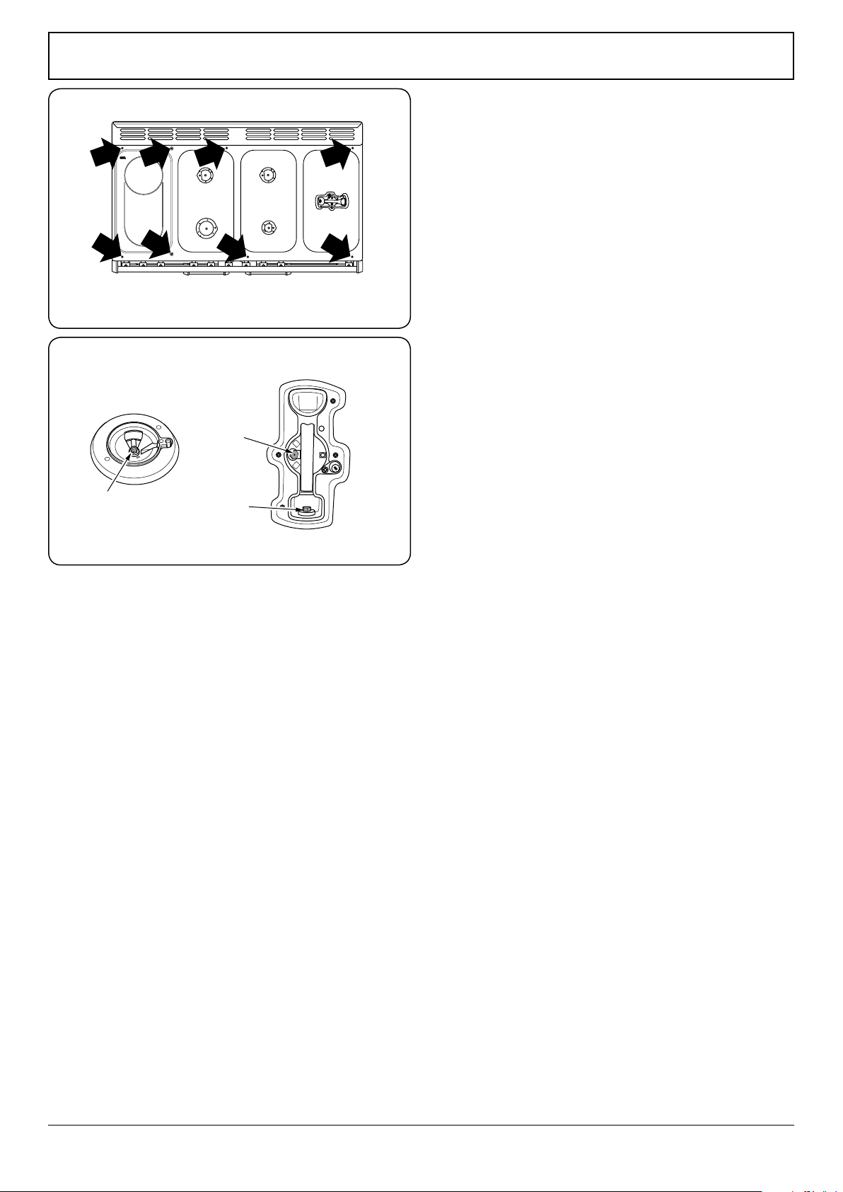
Remove the pan supports, hotplate burner caps and
tops. Remove the screws holding the hotplate burners
to the hotplate (Fig.9-3).
Taking care not to damage the burner electrodes,
carefully lift the hotplate, from underneath disconnect
the earth lead at the right hand rear from the rear cross
member and withdraw the hotplate.
Reassemble in reverse order ensuring that the leads
are reconnected. Take care not to damage the ignition
electrodes of the burners.
It is important that the rear earthing leads are replaced
when the xing screws are retted as they from part of
the cooker earthing.
Check for correct burner operation.
2.2 To Change a Hotplate Tap
DISCONNECT FROM THE ELECTRICITY SUPPLY.
Remove the control panel and hotplate (see 1.2 & 2.1).
Unplug the FSD lead from the rear of the tap. Undo
compression tting at the rear of the tap. Remove the
xings that secure the tap to the gas rail. Disconnect the
ignition switch wiring.
Remove the tap. Remove and discard the gasket seal.
Fit new gasket seal to replacement tap. Re-assemble in
reverse order. Check the appliance is gas sound. Check
hotplate ignition.
2.3 To Replace a Hotplate Burner Injector
DISCONNECT FROM THE ELECTRICITY SUPPLY.
Remove the burner cap and head (Fig.9-4). Remove the
old injector. Fit the new injector.
Note: The wok burner has 2 injectors.
Reassemble in reverse order. Check that the appliance is
gas sound.
2.4 To Change a Hotplate Burner Electrode
DISCONNECT FROM THE ELECTRICITY SUPPLY.
Lift o the pan supports and remove the burner cap.
Remove the screw holding the electrode. Pull the
electrode vertically up suciently to grip the lead
between thumb and forenger. Pull o the electrode,
but keep hold of the lead.
Fit the new electrode to the lead. Fix the electrode in
the burner with the screw.
Fig.9-3
A
B
C
ArtNo.311-0010 Injectors
Fig.9-4
A – Injector, B – Internal injector, C – External injector
Standard burner
Loading ...
Loading ...
Loading ...