Loading ...
Loading ...
Loading ...
WARNING – SERVICING TO BE CARRIED OUT ONLY BY AN AUTHORISED PERSON
Disconnect from electricity and gas before servicing. Check appliance is safe when you have nished.
33
A
B
C
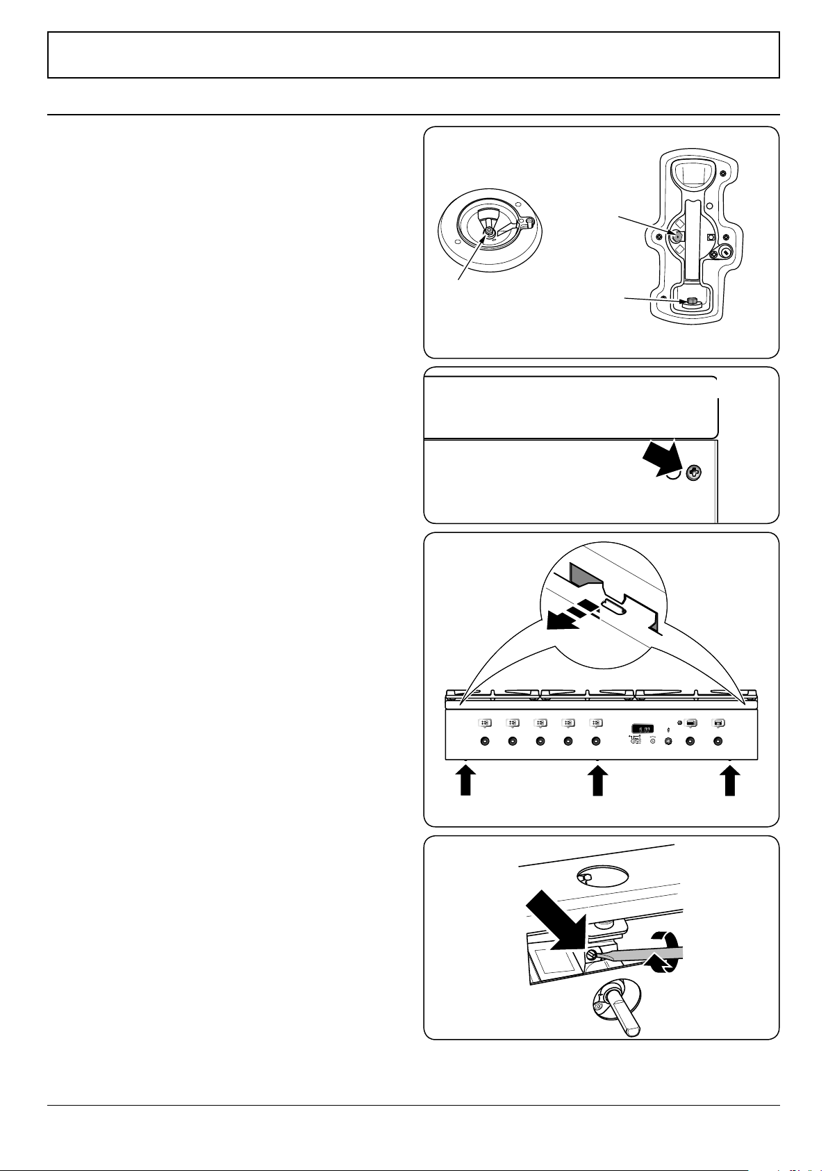
ArtNo.311-0010 Injectors
Fig.8-1
A – Jet, B – Internal injector, C – External injector
ArtNo.0102-0011 - Screwing
the control valve bypass screw
Fig.8-4
Art No 215-0028 - Handrail fascia fixings
Fig.8-2
ArtNo.270-0032 - 90 Prof+ FX - Removing the control panel
Fig.8-3
Conversion from Natural Gas (1.0 kPa)
to LPG X Propane (2.54 kPa)
This conversion must be performed by a competent
person, in accordance with these instructions and
with the local supply company requirements. Read
the instructions before converting this appliance.
Failure to convert the appliance correctly could
invalidate any warranty or liability claims and lead
to prosecution.
The conversion instructions must be used in
conjunction with the rest of the appliance
instruction, in particular for information on
Standards, cooker positioning, connection, hose
suitability, etc.
When servicing or replacing gas-carrying
components, disconnect from the gas before
starting, and check that the appliance is gas sound
after completion.
DO NOT use reconditioned or unauthorised gas
controls.
Disconnect from the electricity supply before
conversion. Before electrical reconnection, check
that the appliance is electrically safe.
Injectors
Remove the burner caps and heads. Remove the old jets.
Fit the new jets: see ‘Technical Data’ section for correct jets.
Reassemble in the reverse order (Fig.8-1).
Tap Adjustment
Removing the Handrail
Remove the handrail. Now remove the 2 cross-headed screws
hidden behind the handrail end brackets (Fig.8-2).
Removing the Control Panel
Pull o all the control knobs and remove the 3 xing screws
underneath the control panel (Fig.8-3).
The control panel will drop down slightly. It is held at the top
by two holes in the top edge, one at each end, that locate on
the tags on the inner panel. Lift the control panel clear of the
tags and pull forwards, taking care not to damage or strain
the wiring.
Bypass Screw Adjustment
Turn the bypass screw on each control clockwise to the stop
(Fig.8-4). Ret the control panel.
8. Conversion to LP Gas
Control panel may dier from that shown
Loading ...
Loading ...
Loading ...