Loading ...
Loading ...
Loading ...
40
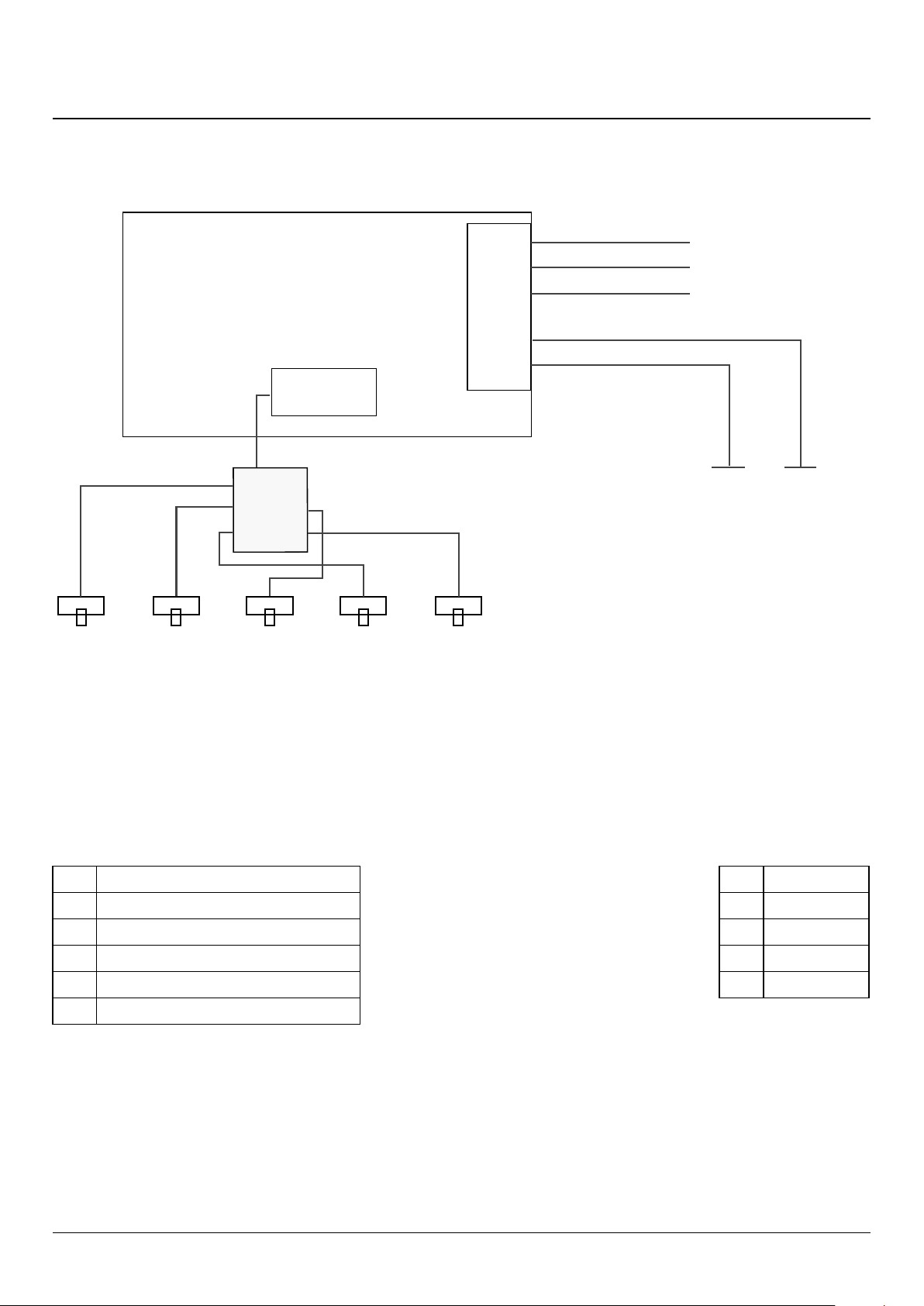
10. Circuit Diagram
Hob
1 2
5 3
4
E
5
4
3
2
1
INTERFACE
BOARD
1
2
5
3 4
INDUCTION UNIT
HOB
DISPLAY
Earth
N(6)
N(5)
L(2) L(3)
On Terminal Block
On Terminal Block
On Terminal Block
w/br
g/y
b
b
br
br
w/br
w/br
w/br
w/br
Key
The connections shown in the circuit diagram are for single-phase. The ratings are for 230 V 50 Hz.
Code Description
1 Left-hand front element
2 Left-hand rear element
3 Right-hand rear element
4 Right-hand front element
5 Centre element
Code Colour
b Blue
br Brown
g/y Green/yellow
w/br White/brown
Loading ...
Loading ...
Loading ...