User Manual
Removing your old thermostat
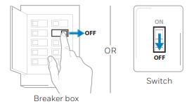
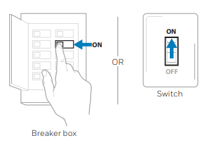
1 Turn power OFF.
WARNING To protect yourself and your equipment, turn off the power at the breaker box or the switch that controls your heating/cooling system.
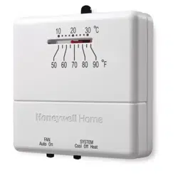
2 Check that your system is off.
Change the temperature on your old thermostat to be above room temperature in heat mode or below it in cool mode. If you don’t hear the system turn on within 5 minutes, the power is off.
Note: If you have a digital thermostat that has a blank display, skip this step.
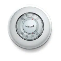
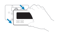
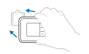
3 Remove the old thermostat’s faceplate.
On most thermostats, you can take off the faceplate by grasping and gently pulling. Some thermostats may have screws, buttons, or clasps.
WARNING Do not remove any wires from your thermostat at this time!
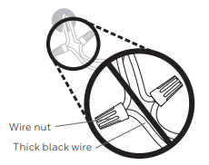
4 Make sure there are no 120/240V wires.
WARNING Do you have thick black wires with wire nuts?
WARNING Is your thermostat 120V or higher?
If you answered yes to either of these questions, you have a line voltage system and the thermostat will not work.
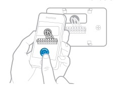
5 Take a picture of how your wiring looks right now.
Be sure to include the letters next to the terminals where the wires are inserted. This will be a helpful reference when wiring your new thermostat.
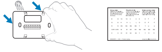
Tip: If the color of your wires has faded or if 2 terminals have the same wire color, use the wire labels provided in the package to label each wire.
6 Record which R-wire(s) you have and write down the color of the wire(s).
Note: Do not include jumpers as a part of your count. The thermostat does not need jumpers.
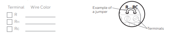
7 Record the remaining wires and write down the color of the wires.
Check mark the wires that are connected to terminals. Next to the check mark, write down the color of the wire. Do not include jumpers as a part of your count.
Check all that apply (Not all will apply):
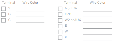
NOTES:
- C does not power the thermostat display or operations; batteries are always required.
- If K was used on old thermostat you have a wire-saver at the equipment. Re-wiring would need to be done so that Y and G are used instead of K.
- The RTH5160 thermostat does not support L/A, S, or U terminals.
- If there are wires in terminals that are not listed, you will need additional wiring support. Visit yourhome.honeywell.com/support to find out if the thermostat will work for you.
8 Disconnect the wires and remove the old wall plate.
Use a screwdriver to release wires from terminals. Then, use a wire label to identify each wire as it’s disconnected. The letter on the wire label should match the letter on the terminal.
Tip: To prevent wires from falling back into the wall, wrap the wires around a pencil
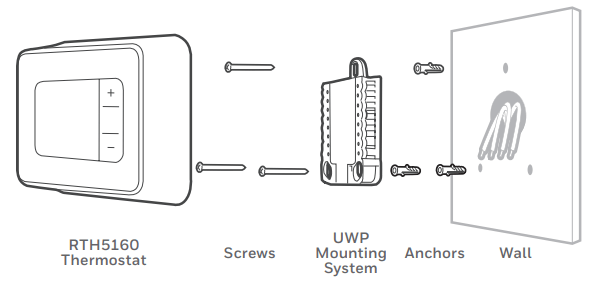
Installing your RTH5160 thermostat
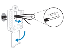
9 Bundle and insert wires through the UWP.
Pull open the UWP and insert the bundle of wires through the back of the UWP.
Make sure at least 1/4 inch of each wire is exposed for easy insertion into the wire terminals
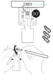
10 Insert the wall anchors.
It is recommended that you use the wall anchors included in the box to mount your thermostat.
You can use the UWP to mark where you want to place the wall anchors.
a) Level the wall plate.
b) Mark the location of the wall anchors using a pencil.
c) Drill the holes.
d) Insert wall anchors.
e) Make sure anchors are flush with wall.
Tip: Use a 7/32 drill bit.
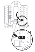
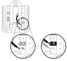
11 Set R-switch position and insert R-wire(s).
Set the R-switch up or down based on your wiring notes in Step 6.
If you have 1 R-wire (R, Rh, or Rc)
1. Set R-switch to the up position.
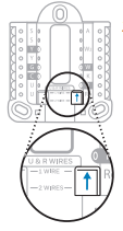
2. Insert your R-wire (R, Rh or Rc) into R-terminal.
or
If you have 2 R-wires (R or Rh, and Rc)
1. Set R-switch to the down position.
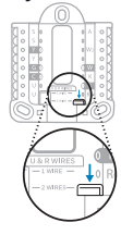
2. Insert your Rc wire into Rc-terminal
3. Insert your R or Rh wire into R-Terminal.
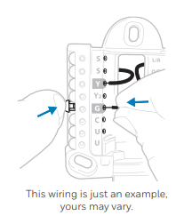
12 Connect remaining wires.
Depress the tabs to put the wires into the inner holes of the corresponding terminals on the
UWP (one wire per terminal) until it is firmly in place.
Gently tug on the wires to verify they are secure.
Tip: If you need to release a wire again, push down the corresponding terminal tab on the side of the UWP.
13 Confirm wiring matches snapshot.
Please confirm wiring matches terminals from the photo you took in Step 5.
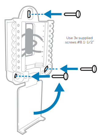
14 Mount the UWP and close the door.
Mount the UWP using the provided screws. Install all three screws for a secure fit on your wall. Close the door after you’re finished.
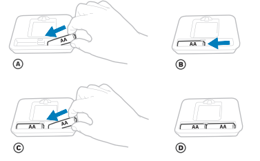
15 Install batteries.
Insert two AA alkaline batteries in the back of the thermostat as shown.
16 Attach your thermostat.
Align the thermostat onto the UWP and firmly snap it into place.
17 Turn your power ON.
Turn on the power at the breaker box or switch that controls the heating/ cooling system.
System Setup
Now that you have installed your thermostat, please follow the steps below to setup your system and personalize your thermostat.
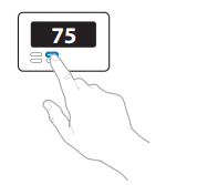
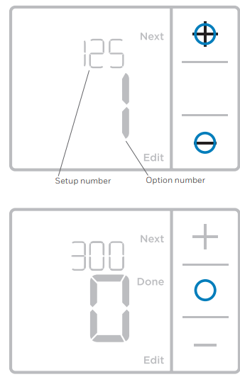
18 Select System Setup options.
Press Edit (-) to change values or select from available options. Then press Next (+) to save changes and advance to the next System Setup number.
See “System Setup options” on the next page for a full list of System Setup numbers and options.
Repeat until all of the System Setup options have been set, and then press Done. The thermostat will save and exit to the home screen.
19 Continue to “System operation settings”.
NOTE: To re-enter the System Setup from the Home Screen, press and hold the Menu button for approximately 5 seconds.
System Setup options
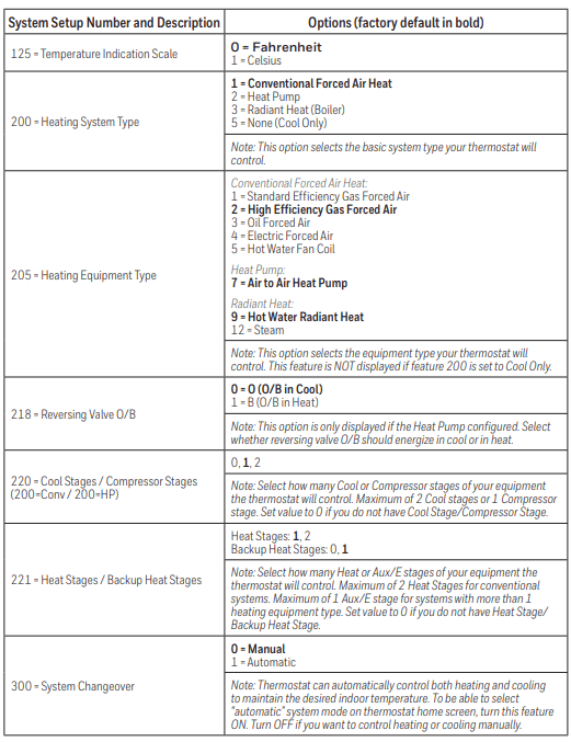
NOTE: Once you have cycled through all of the System Setup numbers, press Done to save and exit to the home screen.
Setup Complete
You have now finished installing and setting up your thermostat.
System operation settings
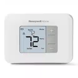
1 Press Menu, and then press the Mode (+) button to cycle to the next available System mode.
2 Cycle through the modes until the required System mode is displayed, and then press Done.
NOTE: Available System modes vary by model and system settings.
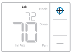
System modes:
- Auto: Thermostat selects heating or cooling as needed.
- Heat: Thermostat controls only the heating system.
- Cool: Thermostat controls only the cooling system.
- Em Heat (only for heat pumps with auxiliary heat): Thermostat controls Auxiliary Heat. Compressor is not used.
- Off: Heating and cooling system is off. Fan will still operate if fan is set to On.
NOTE: Heat On/Cool On may flash for 5 minutes due to compressor protection.
Fan operation settings
1 Press Menu, and then press the Fan (-) button to cycle to the next available Fan mode.
2 Cycle through the modes until the required Fan mode is displayed, then press Done.
NOTE: Available Fan modes vary with system settings.
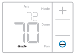
Fan modes:
- Auto: Fan runs only when the heating or cooling system is on.
- On: Fan is always on
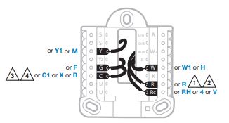
Wiring—conventional systems
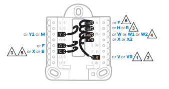
Alternate wiring (conventional systems)
If labels do not match terminals, connect wires as shown below (see notes, below).
NOTES:
1. If you must connect both R and Rc wires, set the R Slider Tab to the down position (2 wires).
2. If your old thermostat had both R and RH wires, set the R Slider Tab to the down position (2 wires). Then connect the R wire to the Rc terminal, and the RH wire to the R terminal.
3. If your old thermostat had only 1 C or C1 wire, connect it to the C terminal. If your old thermostat had 2 C or C1 wires, wrap each separately with electrical tape and do not connect them.
4. C does not power the thermostat display or operations; batteries are always required.
Wiring—heat pump
Connect wires: heat pump
1 Match each labeled wire with same letter on new thermostat.
2 Insert the wires into the matching terminal.
NOTE: If you have difficulty inserting wires, you may have to press down the terminal push button next to the corresponding terminal.
Labels don’t match?
If labels do not match letters on thermostat, see “Alternate wiring conventional systems)“ above.
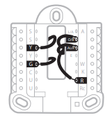
Alternate wiring (for heat pumps only)
NOTES:
1. Keep R Slider Tab in the up position (1 wire).
2. If your old thermostat had both V and VR wires, stop now and contact a qualified contractor for help.
3. If your old thermostat had separate O and B wires, attach the B wire to the C terminal. If another wire is attached to the C terminal, stop now and contact a qualified contractor for help.
4. If your old thermostat had Y1, W1 and W2 wires, stop now and contact a qualified contractor for help.
5. C does not power the thermostat display or operations; batteries are always required.
6. This model doesn’t support the heat pump fault alert (L/A terminal). If this is desired, please contact a contractor for replacement model
Battery replacement
Batteries are required to provide power. Install fresh batteries immediately when the low battery icon appears. The icon appears about two months before the batteries are depleted.
Even if the low battery icon does not appear, you should replace batteries once a year, or before leaving home for more than a month.

If batteries are inserted within two minutes, the time and day will not have to be reset. All other settings are permanently stored in memory, and do not require battery power.
NOTE: When replacing batteries, alkaline batteries are recommended.
Alerts screen
1 You will see the alert icon  and the alert number on the screen.
2 Press Next (+) to see additional alerts, if any. Then press Done to go back to the home screen.
NOTE: If the alert is a critical alert, you may not be able to access the home screen and should call a HVAC professional.
Alerts codes
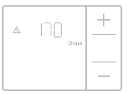
170 Internal Memory Error
- The memory of the thermostat has encountered an error. Please replace the thermostat.
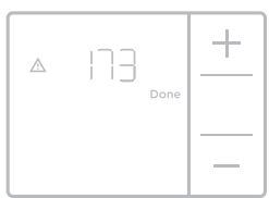
173 Thermostat Temperature Sensor Error
- The sensor of the thermostat has encountered an error. Please replace the thermostat.
405 Low Battery Alert
- The batteries are getting low. Replace them within two months.
407 Critical Low Battery
- The batteries are almost depleted and should be replaced as soon as possible.
Troubleshooting
If you have difficulty with your thermostat, please try the following suggestions. Most problems can be corrected quickly and easily.
Display is blank
- Make sure fresh AA alkaline batteries are properly installed
Cannot change system setting to Cool
- Check System Setup Option 220 to make sure the options are set to either 1 or 2
Fan does not turn on when heat is required
- Check System Setup Option 205 to make sure it is set to match your heating equipment
Heating system is running in cool mode
- Check System Setup Option 200 or 218 to make sure it is set to match your heating and cooling equipment
Heating or cooling system does not respond
- Press Menu and then Mode to set system to Heat. Make sure the temperature is set higher than the Inside temperature.
- Press Menu and then Mode to set system to Cool. Make sure the temperature is set lower than the Inside temperature.
- Check circuit breaker and reset if necessary.
- Make sure power switch at heating & cooling system is on.
- Make sure furnace door is closed securely.
- Wait 5 minutes for the system to respond.
Heat On / Cool On flashing on the screen
- Compressor protection feature is engaged. Wait 5 minutes for the system to restart safely, without damage to the compressor.
Heat pump issues cool air in heat mode, or warm air in cool mode
- Check System Setup Option 200 or 218 to make sure it is set to match your heating and cooling equipment
1 year limited warranty
Honeywell warrants this product, excluding battery, to be free from defects in the workmanship or materials, under normal use and service, for a period of one (1) year from the date of purchase by the consumer. If at any time during the warranty period the product is determined to be defective or malfunctions, Honeywell shall repair or replace it (at Honeywell’s option).
If the product is defective,
i) return it, with a bill of sale or other dated proof of purchase, to the place from which you purchased it; or
ii) call Honeywell Customer Care at 1-800-468-1502. Customer Care will make the determination whether the product should be returned to the following address: Honeywell Return Goods, Dock 4 MN10-3860, 1985 Douglas Dr. N., Golden Valley, MN 55422, or whether a replacement product can be sent to you.
This warranty does not cover removal or reinstallation costs. This warranty shall not apply if it is shown by Honeywell that the defect or malfunction was caused by damage which occurred while the product was in the possession of a consumer.
Honeywell’s sole responsibility shall be to repair or replace the product within the terms stated above. HONEYWELL SHALL NOT BE LIABLE FOR ANY LOSS OR DAMAGE OF ANY KIND, INCLUDING ANY INCIDENTAL OR CONSEQUENTIAL DAMAGES RESULTING, DIRECTLY OR INDIRECTLY, FROM ANY BREACH OF ANY WARRANTY, EXPRESS OR IMPLIED, OR ANY OTHER FAILURE OF THIS PRODUCT.
Some states do not allow the exclusion or limitation of incidental or consequential damages, so this limitation may not apply to you.
THIS WARRANTY IS THE ONLY EXPRESS WARRANTY HONEYWELL MAKES ON THIS PRODUCT. THE DURATION OF ANY IMPLIED WARRANTIES, INCLUDING THE WARRANTIES OF MERCHANTABILITY AND FITNESS FOR A PARTICULAR PURPOSE, IS HEREBY LIMITED TO THE ONE-YEAR DURATION OF THIS WARRANTY.
Some states do not allow limitations on how long an implied warranty lasts, so the above limitation may not apply to you. This warranty gives you specific legal rights, and you may have other rights which vary from state to state.
If you have any questions concerning this warranty, please write Honeywell Customer Relations, 1985 Douglas Dr, Golden Valley, MN 55422 or call 1-800- 468-1502. In Canada, write Retail Products ON15-02H, Honeywell Limited/ Honeywell Limitée, 35 Dynamic Drive, Toronto, Ontario M1V4Z9