Loading ...
Loading ...
Loading ...
38
Australia
a
b
e
f
c
d
1
2
�
A
Key
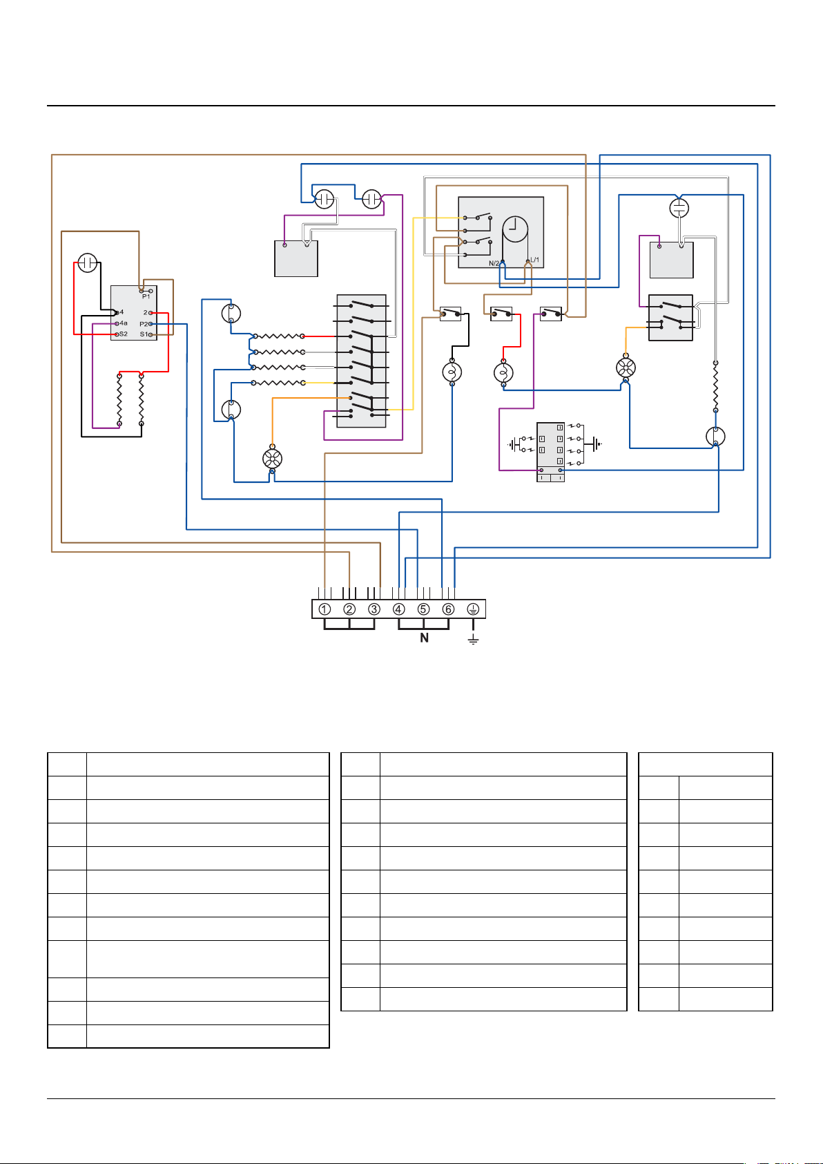
The connections shown in the circuit diagram are for single-phase. The ratings are for 240V 50Hz.
Colour Code
b Blue
br Brown
bk Black
or Orange
r Red
v Violet
w White
y Yellow
g/y Green/yellow
gr Grey
10. Circuit Diagram
Code Description
A1 Grill control
A2 Left-hand grill element
A3 Right-hand grill element
B1 Left-hand MF oven control
B2 Left-hand MF oven control switch
B3 Left-hand MF oven base element
B4 Left-hand MF oven top element (outer pair)
B5
Left-hand MF oven browning element (inner
pair)
B6 Left-hand MF oven fan element
B7 Left-hand MF oven oven fan
C Clock
Code Description
D1 RH fan oven control
D2 RH fan oven thermostat
D3 RH fan oven element
D4 RH oven fan
F1 Oven light switch
F2 Oven lamp
H1 Ignition switch
H2 Ignition generator
I Neon
J Thermal cut-out
Loading ...
Loading ...
Loading ...