Loading ...
Loading ...
Loading ...
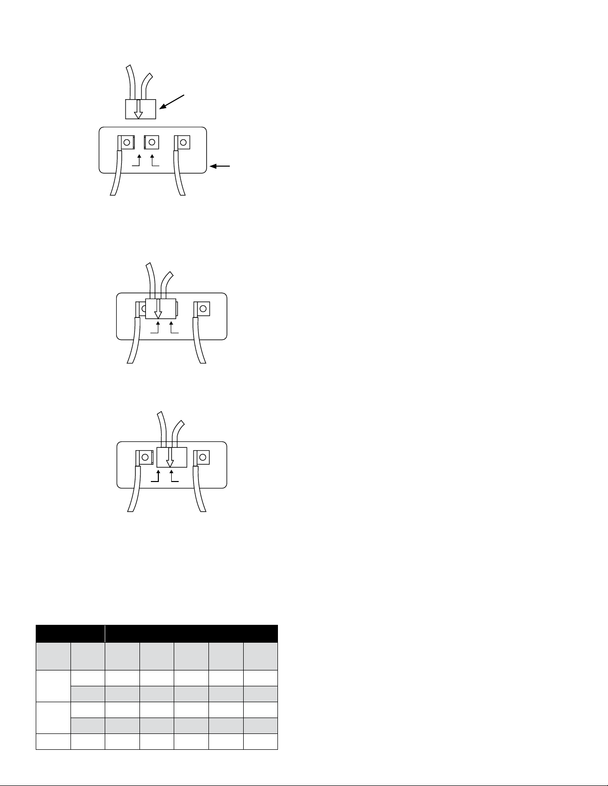
In #2, the motor's switch is set for 230 V. The white arrow on the voltage
change device points directly to the 230 V arrow on the terminal board.
#2 (Set to 230 V)
230 115
L1
L2
L1
L2
230 115
L1
L2
230115
Brown White
In #3, the motor's switch is set for 115 V. The white arrow on the voltage
change device points directly to the 115 V arrow on the terminal board.
#3 (Set to 115 V)
230 115
L1
L2
L1
L2
230 115
L1
L2
230115
Brown White
In #1, the motor's switch is shown before the black voltage
change device is pressed down onto the voltage terminals.
NOTE: DO NOT MOVE LEAD WIRES ON L1 & L2.
#1
230 115
L1
L2
L1
L2
230 115
L1
L2
230115
Terminal
Board
Voltage Change Device
Brown
White
FOR 1-1/2 HP MODELS
FOR 2 HP MODELS
2 HP models are available in 230 Volts only.
INSTALLATION
Pump Location
Install the pump in a clean, dry, and ventilated location that
provides adequate drainage, room for servicing, and protection
from freezing temperatures.
s CAUTION
!
The pump must be protected from the elements
and freezing temperatures. The motor is not water-resistant.
Bolt down the pump evenly on a good foundation, preferably concrete, to
prevent the development of unnecessary stress. Locate the pump as close
as possible to the water supply to reduce friction losses in the suction pipe
and to provide for maximum capacities. A foot valve must be used.
Suction Pipe
Use only new, clean pipe or hose the same size as that of the pump suction
tapping. If the pump is installed any appreciable distance away from the
water supply, increase the suction pipe by one size. The suction pipe must
always slope upwards from the water source to the pump to avoid air
pockets in the line. It is advisable to use a 90° or 45° elbow on the suction
line. This enables the pump to prime sooner and also prevents kinking
of the hose. A check valve is recommended to ensure easier priming.
In cases where a maximum volume of water is required over a prolonged
period, the suction line should be led almost horizontally to the pump.
Use non-toxic thread compound on all pipe joints, and tighten all
connections thoroughly. Connect a strainer to the bottom end of the
suction pipe and ensure that it is well submerged at all times.
s WARNING
!
ELECTRICAL PRECAUTIONS
All wiring, electrical connections, and system grounding must comply with
the National Electrical Code (NEC) and with any local codes and ordinances.
Employ a licensed electrician.
s WARNING
!
RISK OF ELECTRICAL SHOCK
Grounding the Motor
Wiring to this pump must be installed and maintained in accordance with
the National Electrical Code or your local electric code. If more information
is needed, call your local licensed electrician or your power company.
It is recommended that a permanent ground connection be made to the
unit using a conductor of appropriate size from a metal underground water
pipe or a grounded lead in the service panel. Do not ground to a gas supply
line. Do not connect to electric power supply until unit is permanently
grounded. Connect the ground wire to the approved ground and then
connect to the terminal provided.
s WARNING
!
RISK OF ELECTRICAL SHOCK
Wiring: Make sure the voltage and frequency of the power supply agrees
with the voltage of the pump. If in doubt, check with the power company.
Connect wiring to terminal board located inside motor terminal box cover.
Motor Wire Gauge (AWG)
HP Volts
25 ft
(8 m)
50 ft
(15 m)
100 ft
(30 m)
150 ft
(46 m)
200 ft
(61 m)
1
115 14 12 10 8 6
230 14 14 14 14 12
1-1/2
115 12 12 8 6 6
230 14 14 14 12 12
2 230 14 14 14 12 10
Table 1
4
Loading ...
Loading ...
Loading ...