Loading ...
Loading ...
Loading ...
10 11ASSEMBLY INSTRUCTIONS FOR TROLLEY
Converting the unit to natural gas
1. Turn off the gas supply valve on the gas cylinder. Ensure
that all gas controls on the BBQ are in the OFF position.
2. Disconnect the hose and regulator from the gas
cylinder and disconnect the gas hose from the barbecue
gas inlet using a 19mm open-ended spanner / wrench.
3. Open hood and remove all cooking plates, grills and
vaporisers from the BBQ.
4. Remove the ‘R’ shaped locking clips that hold each
burner in place and remove all burners from the
barbecue. This needs to be done at the rear of the BBQ.
5. The gas injectors (also known as jets or nozzles) for
each burner are located within deep pockets at the rear
of the BBQ.
6. Remove each gas injector from the end of each jet
holder using a 6mm socket spanner/ wrench, turning
gently in a counter clockwise direction. Be careful not
to block the orifice at the end of the valve where the gas
injector is fitted and do not remove any of the thread
sealing compound from the orifice where the injector is
located.
7. Check the identification mark stamped on the Hex Head
of the injector to confirm that it is the correct size (NG:
2.10mm). Screw correct Jets back into place.
8. When fitting the NG gas injectors to the end of the jet
holder be sure to seat the injector correctly on the
thread before turning it in a clockwise direction until it
is seated firmly in place. Do not over-tighten.
9. Replace all parts into position in the BBQ
10. Refit the burners and secure with the locking clips that
hold each burner is position. Replace the vaporisers,
grills and cooking plates. Note: Check the operation
of each burner- it may be necessary to open the air-
mixture screw (located at the burner venturi) a couple of
turns to get the correct flame.
11. Replace the LPG gas type label with the natural gas
label supplied. 12. Leak test using same procedure for
LPG, as detailed on page 4.
12. Connect the natural gas hose and regulator (where
applicable) to the gas inlet on the barbecue. Tighten
firmly but do not over tighten. Connect gas regulator
to gas source line. Perform leak test using same
procedure as for LPG.
ASSEMBLY AND GAS CONNECTION INSTRUCTIONS FOR SIDE BURNER
ASSEMBLY AND GAS CONNECTION INSTRUCTIONS FOR SIDE BURNER
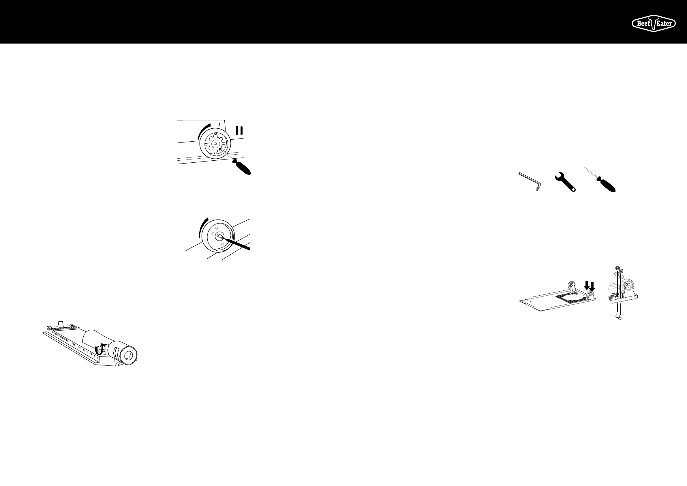
Turn down adjustment
When converting to natural gas the turndown setting will
need to be adjusted to give a satisfactory flame on low
setting on each burner.
• Remove knobs from valve shafts. For ignition valves
the low flame adjustment screw is located on the lower
right hand corner of the front of the valve body.
High
Low
Off
• Using a flat bladed screwdriver, turndown adjustment
screw should be fully inserted and then rotated
• For non-igntion valves the screw is located inside the
knob spindle. Use a 2.5mm wide flat blade screwdriver
full inserted and make a ¾ turn counter clockwise.
Low
• Repeat for other valve.
• Following of the gas and leak testing as per previous
steps, light both burners and set to high.
• One burner at a time turn the valve shaft to lowest
setting, observe the flame to ensure a small steady
flame in achieved.
• Turn off burners and replace control knobs, ensuring
the knob is in the correct orientation when valve is in
“OFF” position.
Fixed Installation - Portable LP Gas/Propane.
BeefEater LPG/propane barbecues are designed to operate
at 2.75Kpa (11”WC).
Connect the gas supply line to the barbecue inlet located on
the right side of the appliance using either hard plumbing,
or a flexible hose connected to a bayonet point, also known
as a quick connect fitting.Refer to AS 5601 or your local
installation code for pipe sizing details.Secure all joints
spanner (wrench) tight but do not over-tighten.
Aeration Screw Adjustment
ASSEMBLY INSTRUCTIONS
FOR TROLLEY
Test gas pressure by removing the last burner from the
left hand side of the barbecue and attaching a hose and
pressure gauge to the end of the gas valve.Turn on 2
burners and check the pressure.Inlet pressure should be
11.0” WC or 2.75 kPa.
Fixed Installation - Natural Gas
(Natural Gas installation should be carried out by a qualified
gas fitter).
BeefEater Natural Gas barbecues are designed as low-
pressure appliances (4.0” WC, 1.00KPa).
Fit the natural gas regulator supplied directly to the
barbecue inlet located on the right side of the appliance
using either hard plumbing, or a flexible hose connected to
a bayonet point, also known as a quick connect fitting.Refer
to AS 5601 or your local installation code for pipe sizing
details.Secure all joints spanner (wrench) tight but do not
over-tighten.
Test gas pressure by removing the last burner from the
left hand side of the barbecue and attaching a hose and
pressure gauge to the end of the gas valve.Turn on 2
burners and check the pressure.Inlet pressure should be
4.0” WC or 1.00 kPa.
Australia only (applies to all gas types) : Where a mobile
appliance is to be connected to a fixed gas supply via a
flexible hose connection, a retaining tether of adequate
strength shall be fixed to the appliance and be suitable to
be fixed to the wall within 50mm of each connection
point. The length of the tether shall not exceed 80% of the
length of the hose assembly. In this way, if the barbecue
is accidentally moved, the chain stops the barbecue from
stretching the hose.
The barbecue appliance must be isolated from the gas
supply piping system by closing its manual shutoff valve
during any pressure testing of the gas supply piping system.
Before You Start
Note the tools you will need before you begin.
Check for damaged or missing parts, and consult your
retailer if necessary.
Many components and panels are covered with a protective
sheet of plastic. You will need to remove this plastic covering
from all surfaces, especially where two panels join. It is
a good idea to leave some plastic on the panels during
assembly to protect the stainless steel during the assembly
process. Ensure however that all plastic covering is removed
on completion.
Always assemble on a clean, smooth, flat working surface
that will not scratch the surface of the stainless steel.
Allen Key Adjustable
spanner/
wrench
Phillips head
screwdriver
1) Fit The Fixed Castors
Fit the fixed castors into the holes in the bottom of the base.
At this step, use only two Allen head screws, washers and
nuts for each castor in the positions shown. The two outside
screws will be put on in step 3.
Spanner/wrench tighten immediately.
Note lip
ends here
Loading ...
Loading ...
Loading ...