Loading ...
Loading ...
Loading ...
8 9
ASSEMBLY INSTRUCTIONS INSTALLATION INSTRUCTIONS
ASSEMBLY INSTRUCTIONS INSTALLATION INSTRUCTIONS
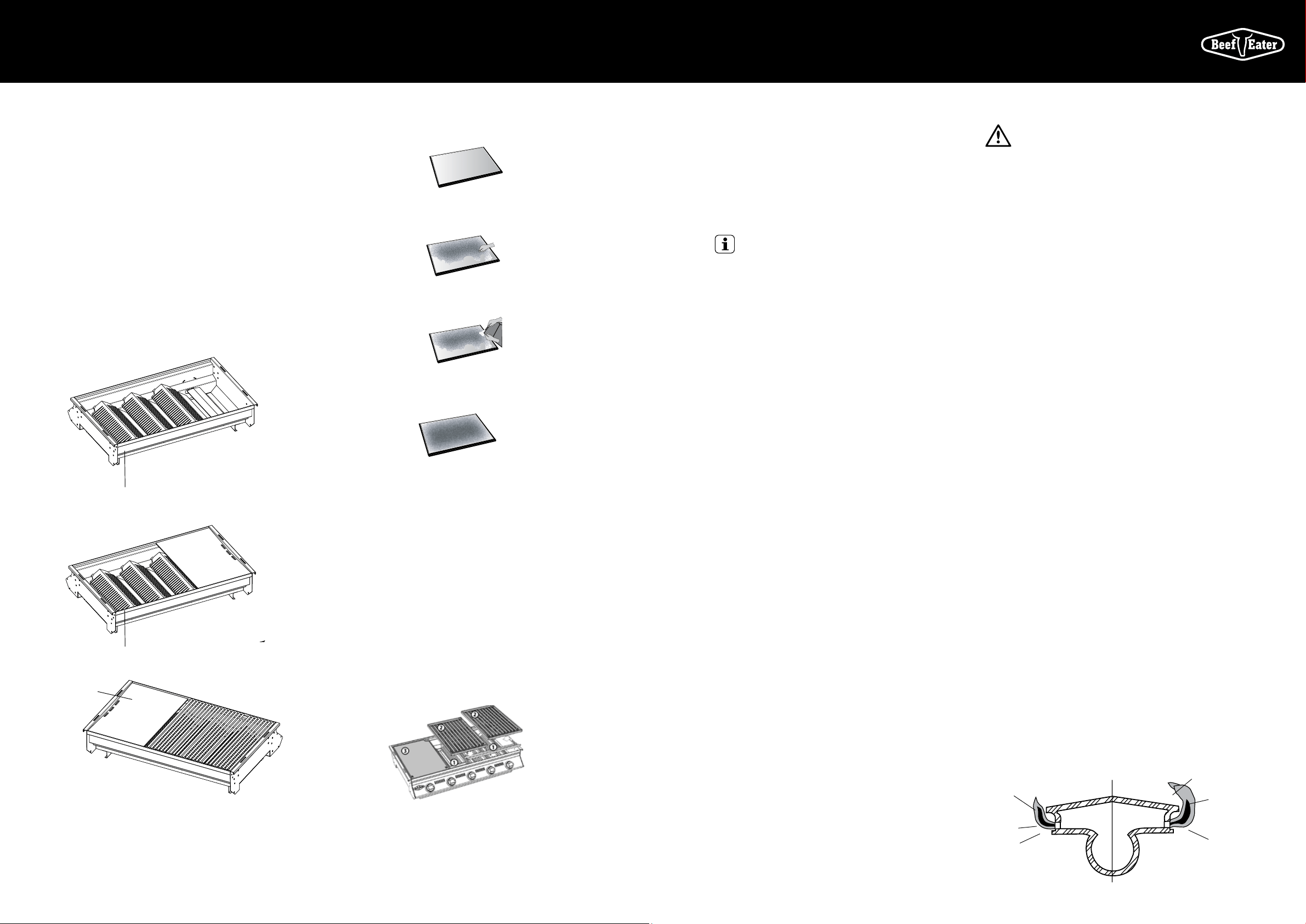
Fitting the cooking plates and grills
We recommend fitting the plate to the left-hand side of the
barbecue frame (with the drain hole to the extreme left).
The grill or grills can be fitted to the right hand side of the
barbecue frame. Grills must always be positioned over the
Vaporizer grids. See Fig 13.
BeefEater 2, 3 & 4 burner barbecues come standard with 1/2
plate and 1/2 grill and are approved for use with a maximum
of 50% plate over the entire cooking area. Do not replace
the grill with another plate as this will cause severe heat
damage to the appliance.
BeefEater 5 burner barbecues come standard with 1/3 plate
and 2/3 grill and are approved for use with a maximum of
2/3 plate. Do not cover the entire surface of the barbecue
frame with plates as this will cause severe heat damage to
the appliance.
FIG 12
FIG 13
FIG 14
NOTE: the channels overlap in the centre, and must slope
to each end of the BBQ such that there is one drain hole at
each end.
The drain holes in the Grill and Plate are to be positioned
towards the front of the BBQ, above the Channel which
collects and drains away the grease.
No other modification is required, and the BBQ assembly is to
be performed as per the BBQ Instruction Manual.
IMPORTANT
This appliance must be installed in accordance with the
installation requirements of the LOCAL GAS and ELECTRICITY
supply authority, or the appropriate installation code issued
by the A.G.A. and the A.L.P.G.A. Servicing should only be
carried out by an authorised person.
This appliance:
Must have a minimum clearance from combustible
materials of all sides of the barbecue of 450 mm (18”).
Should not be installed under or on any combustible surface.
Must be tested for safe and proper operation on completion
of installation and prior to leaving the site. Keep ventilation
opening of any cylinder enclosure clear and free of any debris.
Check ‘Gas Type’ label & data plate attached to right side
of barbecue.
LP Gas / Propane
A. Fit the regulator to the LPG cylinder. See regulator
connection page 2, Fig 1.
B. Connect the hose and regulator to the gas inlet at the
right hand side of the barbecue. The gas inlet of the
barbecue is 3/8 SAE male flare fitting. Do not subject the
hose to twisting.
C. Secure all joints spanner (wrench) tight but do not over-
tighten. Check for leaks after turning on gas supply by
brushing onto all joints a solution of water and detergent.
Bubbling of the solution will indicate leaks. Re-tighten or
reseal any leaking joints. If leaks persist turn off the gas
supply and consult your dealer.
D. Following operating instructions light each burner and
check for a clear blue flame with just a tip of yellow.
Excess yellow tipping can be adjusted using the screw
on the side of the burner. Turn the screw in a counter
clockwise rotation to remove the yellow.
E. For mobile trolley installations, when using a flexible
hose to a fixed fuel source, a chain or similar restraining
device must be fitted to prevent strain on the gas supply
hose or accidental uncoupling. Do not subject the hose
to twisting.
F. For build-in situations allow adequate ventilation for
the barbecue and cylinder. Keep the cylinder away
from heat and allow clear access to the gas supply
hose and regulator.
WARNING
WARNING
The flexible PVC hose assembly supplied must not be
exposed to temperatures in excess of 60°C (140°F).
DO NOT expose to the sun’s direct heat and DO NOT allow
the hose to come in contact with the hot surface of the
barbecue body.
Recommended minimum LPG cylinder capacity for use with
this appliance is 4kg. Maximum LPG cylinder capacity for
use with this appliance is 10kg.
Do not install the gas cylinder beneath the barbecue unless
in conjunction with an approved separator panel.
Natural Gas
(Natural Gas installation should be carried out by a qualified
gas fitter).
A. BeefEater Natural Gas barbecues are designed
for low pressure (4.0” WC, 1.00KPa) to be used
as freestanding units, trolley mounted, or built
into brickwork.
B. Fit the natural gas regulator supplied directly to the gas
inlet via hard plumbing and install a shutoff valve within
easy reach in the gas line. Secure all joints spanner tight
but do not over-tighten. Check for leaks after turning
on gas supply by brushing onto all joints a solution
of water and detergent. Bubbling of the solution will
indicate leaks. Re-tighten or reseal any leaking joints.
If leaks persist turn off the gas supply and consult the
manufacturer or dealer.
C. Test gas pressure by removing the last burner from the
left hand side of the barbecue and attaching a hose and
pressure gauge to the end of the gas valve. Turn on two
burners and check the pressure. Inlet pressure should
be 4.0” WC or 1.00 KPa.
D. Following operating instructions light each burner and
check for a clear blue flame with just a tip of yellow. Avoid
excess yellow tipping by adjusting the screw on the side of
the burner, counter-clockwise rotation removes yellow.
E. For mobile trolley installations a chain or similar
restraining device must be fitted to prevent strain or
accidental uncoupling of the gas supply line.
D. For build-in situations allow adequate ventilation for
the barbecue.
The barbecue appliance must be isolated from the gas
supply piping system by closing its manual shutoff valve
during any pressure testing of the gas supply piping system.
Installation to Natural Gas must be carried out by an
authorised person.
FIG 15
FIG 16
FIG 17
FIG 18
Fitting the grease tray
Neatly line the drip tray with a couple of sheets of
aluminium foil. Cut the foil to shape and make sure that the
foil sits on the bottom of the tray or corners of the foil so
that it does not foul in the tray sliders on the bottom of the
barbecue frame. The foil will aid in clean up & help reduce
leakage. Fill the tray with a 6mm (1/4”) layer of dry sand
or other non-combustible absorbent material to absorb
grease. Change the foil and absorbent material regularly to
reduce the likelihood of a drip tray fire. See Fig 15-18.
NOTE: Draining channels need to be assembled on selected
models.
To correctly assemble the advance grill, plate and draining
channel
The Draining channel kit (2 pieces, labelled ‘1’ above) is to
be placed on the inside front ledge of the barbecue body with
the Grill (labelled ‘2’) and Plate (labelled ‘3’) fitted on top, and
lock it in place.
Rear of barbecue
Neatly line the drip tray with aluminium foil
Add absorbent material
Spread the absorbent material out evenly
Ensure that the absorbent material is not more
than 6mm deep.
Rear of barbecue
Yellow tipping
Right Wrong
Yellow tipping
Light blue
Dark blue
Dark blue
Light blue
Grease drain hole
Loading ...
Loading ...
Loading ...