To ensure that critical air gaps are maintained under the appliance, we recommend that this appliance is mounted on a solid base and that the feet do not sink into any carpet or soft flooring.
The kitchen floor must be able to carry the weight of the appliance plus the additional weight of cookware and bake ware and food.
• If an appliance hood is to befitted, refer to the manufacturer's instructions regarding fixing height.
• The appliance corresponds to device class 1, i.e. it may be placed with the rear and one side to kitchen walls, kitchen furniture or equipment of any size. The kitchen furniture or equipment on the other side may only be of the same size or smaller.
• Any kitchen furniture next to the appliance must be heat-resistant (212 °F min.).
Room ventilation
All rooms require an openable window, or equivalent, and some rooms will require a permanent vent as well.
The air for combustion is taken from the room air and the exhaust gases are emitted directly into the room.
Good room ventilation is essential for safe operation of your appliance.
If the room where the appliance is installed does not have a door or a window that opens directly to the outer environment, there must definitely be a fixed ventilation opening in the room. The fixed ventilation must be nonadjustable and non-closable.
On the doors or windows that open directly to the outer environment, there must be a ventilation opening with the dimensions specified based on the total gas power of the appliance (as shown below). You can find the gas power and ventilation opening match-up in the table below.
Total gas
consumption
(BTU/h)
min. Ventilation opening (inch2)
0-6800
16
6800-10200
19
10200-13600
27
13600-20500
47
20500-27300
62
27300-34100
78
34100-39200
93
39200-44400
109
44400-52900
124
52900-58000
140
58000-64800
155
64800-81900
194
If the doors or windows that open directly to the outer environment do not have openings corresponding to the ventilation opening specified according to the total gas power of the product, there must definitely be a fixed ventilation opening in the doom. The fixed ventilation opening should also be in compliance with the values in the gas power-ventilation opening table.
There should be a minimum clearance of 10 mm on the bottom edge of the door -that opens to the inner environment- in the room where the product is installed. You must make sure that items such as carpets, floorings, etc. do not cover this clearance when the door is closed.
The cooker may be located in a kitchen, kitchen/diner or a bed-sitting room, but not in a room containing a bath or shower. The cooker must not be installed in a bed-sitting room of less than 20m3.
Do not install this appliance in a room below ground level unless it is open to ground level on at least one side.
Be sure your appliance is properly installed and grounded by a qualified technician in accordance with the National Fuel Gas Code ANSI Z223.-latest edition, or in Canada, CAN/CGA B149.1, and CAN/CGA B149.2, and National Electrical
Code ANSI/NFPA No.70 - latest edition, or in Canada CSA Standard C22.1, Canadian Electrical Code, Part 1 and local code requirements.
Important notes to the consumer
Keep this manual for future reference.
As when using any range generating heat, there are certain safety precautions you should follow. These are listed in the front of this manual. Read and follow carefully.
Your range must be installed and grounded properly by a qualified installer or service technician.
To eliminate the need to reach over the cooktop, cabinet storage space above the cooktop should be avoided.
Installation and connection
For installation the appliance must be connected in accordance with all local electrical and/or gas regulations.
Hidden surfaces may have sharp edges. Use caution when reaching behind or under appliance.
The appliance must be placed directly on the floor. It must not be placed onto a base or a pedestal.
Clearances & Dimensions
Dimensions that are shown in figures 1 and 1A must be used. Given dimensions provide minimum clearance. There needs to be a 30-inch minimum clearance between the top of the cooking surface and the bottom of unprotected wood or metal cabinets or a 24-inch minimum when bottom of wood or metal cabinets are protected by not less than a 1/4-inch flame retardant millboard covered with not less than no. 29 msg sheet-steel, 0.015- inch stainless steel, 0.024-inch aluminum or 0.020-inch copper.
To eliminate the risk of burns or fire by reaching over heated surface units, cabinet storage space located above the surface units should be avoided. If cabinet storage is to be provided, the risk can be reduced by installing a range hood that projects horizontally a minimum of 5 inches beyond the bottom of the cabinets.
A package of anti-tip device is supplied with product. Anti-tip devices, screws, fixing plugs and anti-tip installation template is provided in this package.
Anti-tip brackets must be secured to both wall and floor and must be used for the both rear feet.
1. Place the back edge of the template against the wall behind the range.
2. Center the template in the gap in where the range will be installed.
3. Place anti-tip brackets on the template and mark locations of the screw holes on the floor and wall (4 marks for 4 screws).
4. Remove the brackets and templates. Drill pilot holes on the marks in accordance with fixing plug and screw dimensions.
5. Screw and secure anti-tip brackets on the floor with screws.
6 . Please ensure the product is level by adjusting the four feet at the bottom by turning left or right and align level with the worktop.
7. Slide range into place making sure the antitip device engages the foot at rear of range.
8. After installation cautiously grip the rear of the range to ensure the anti-tip bracket is engaging the rear foot of range.
Connection to the gas supply
This appliance has been tested in accordance with the following standards:
• ANS Z21.1 -Household Cooking Appliances
• CSA1.1 - Household Cooking Appliances
• CAN/ CSA-C 22.2 No 61-M89 Household Cooking Ranges.
• In Canada, installation must be in accordance with CAN 1-B149.1 and 2 Installation Codes for Gas Burning Appliances and or local codes.
• It is the responsibility of the owner and the installer to determine if additional requirements, such as local codes and/or standards, apply to specific installations. The installation must conform with local codes or, in the absence of local codes, with the National Fuel Gas Code, ANSI Z223.1/NFPA 54 or, in Canada, the Natural Gas and Propane Installation Code, CSA B149.1.
For Massachusetts Installations:
1. Installation must be performed by a qualified and licensed contractor, plumber or gas fitter qualified and licensed by the state, province or region where this appliance is being installed.
2. Shut-off valve must be a "T" handle gas cock.
3. Flexible gas connector must not be longer than 36 inches.
High Altitude Installation note:
This cooker is ETL certified for safe operation up to an altitude of 2.000 ft. without any modifications. For higher altitudes, please contact with Service.
Connect to the gas supply
Important note for LP users
The range is shipped from the factory for use with natural gas. For use with propane (LP) gas, your range must first be converted using tthe LP conversion kit.
The gas connection is located at the back of the range.
Shut off main gas supply valve before disconnecting the old range and keep it off until the new hook-up has been completed.
The cooker can be installed using rigid pipe or a CSA, cCSAus, UL International-certified flexible metal appliance connector. If using a flexible connector, always use a new connector.
Apply pipe joint compound or tape appropriate for use with Natural gas around all male pipe threads to prevent leaks.
If not already present, install gas shut off valve in an easily accessible location. Make sure all users know where and how to shut off the gas supply to the range.
Gas supply pressure for checking the regulator setting is 5" WC.
If your product has only one gas outlet;
• Before connecting the gas hose, make sure that the gas hose outlet at the back of the product is on the same side of the product as the natural gas valve.
• If the gas hose outlet and the natural gas valve do not face on the same side, make sure that the hose does not pass through the hot area when connecting it.
If your product has two gas outlets;
• One of the two outlets is sealed with a blind plug and the other one with a plastic plug. Locations of the blind plug and plastic plug may be different depending on the product.
• Before gas connection, make sure that the natural gas valve and the gas hose outlet of the product to be connected to the gas is on the same side.
• If the natural gas valve and the gas hose outlet sealed with plastic plug face on the same side, make the gas connection as shown in the figure below.
• If the natural gas valve and the gas hose sealed with blind plug face on the same side, remove and dispose the plastic plug. Take out the blind plug and close the gas hose outlet where gas connection will not be made with a new (unused) sealing gasket.
• Make the gas connection as shown in the figure below on the gas hose outlet near the natural gas valve.
Risk of fire:
If you do not make the connection according to the instructions below, there will be the risk of gas leakage and fire. Our company cannot be held responsible for damages resulting from this.
Gas connection must be made by the authorised service provider only.
Gas connection of the product must definitely be made through the gas hose outlet near the natural gas valve.
Plastic plug must be disposed, and the gas hose outlet that will not be used must be sealed with the blind plug.
When closing the gas hose outlet that will not be used, you must definitely use a new and unused sealing gasket._
Leakage check at the connection point
• Make sure that all knobs on the product are turned off. Make sure that the gas supply is open. Prepare soapy foam and apply it onto the con-nection point of the hose for gas leakage control.
• Soapy part will froth if there is a gas leakage. In this case, inspect the gas connection once again.
• If your product has two gas hose outlets, make sure that the unused gas outlet is sealed with a blind plug. Prepare soapy foam and apply it onto the connection point of the blind plug to check for gas leaks. Soapy part will froth if there is a gas leakage. In this case, inspect the blind plug connection again.
• Instead of soap, you can use commercially available sprays for gas leak check.
Gas Pressure Regulator
You must use the gas pressure regulator supplied with this range, For proper operations the inlet pressure to the regulator should be as follows:
Natural Gas:
Minimum pressure: 5” of Water Column
Maximum pressure: 13” of Water Column
Propane Gas:
Minimum pressure: 12” of Water Column
Maximum pressure: 13” of Water Column
Rigid Pipe Method
The configuration of the rigid pipe connection will vary depending on the location of the gas pipe stub.
1. Make sure circuit breaker is off and then plug range cord in to electrical outlet.
2. Push range back into position insuring that range leg slides under the anti-tip bracket. The range will sit 3/4" away from the wall when properly installed.
3. Carefully tip range forward to insure that antitip bracket engages and prevents tip-over.
4. Connect pipe to range at union.
5. Proceed to "Test for Gas Leaks"
Flexible Connector Method
Refer to Figure below for details.
1. Install male 1/2" flare adaptor at the 1/2" NPT internal thread of the range inlet. Use a backup wrench on the elbow fitting to avoid damage.
2. Install male 1/2" or 3/4" flare union adapter on the NPT internal thread, of the manual shutoff valve.
3. Connect flexible metal appliance connector.
4. Make sure circuit breaker is off and then plug range cord in to electrical outlet.
5. Push range back into position insuring that range leg slides under the anti-tip bracket. The range will sit 3/4" away from the wall when properly installed.
6. Carefully tip range forward to insure that antitip bracket engages and prevents tip-over.
7. Proceed to "Test for Gas Leaks"
Test for Gas Leaks
Leak testing of the appliance shall be conducted according to the manufacturer's instructions.
Turn on gas. Apply a non-corrosive leak detection fluid to all joints and fittings in the gas connection between the shut-off valve and the range. Include gas fittings and joints in the range if connections may have been disturbed during installation. Bubbles appearing around fittings and connections indicate a leak.
If a leak appears, turn off supply line gas shut-off valve and tighten connections. Re-test for leaks by turning on the supply line gas shut-off valve. When leak check is complete (no bubbles appear), test is complete. Wipe off all detection fluid residue.
Test burner function
1. Turn on power at breaker
Verify that wiring in house is correctly installed. If not call Service and do not operate the range.
If display screen flashes and beeps continuously, the wiring is incorrectly installed. Verify that wiring in house is correctly installed.
2. Test range top burners
Test burner ignition: Select a range top burner knob. Push and turn the knob counter clockwise to HI. The igniter module will produce a spark sound. Once the air has been purged from the supply lines, the burner should light within four seconds.
Test flame: High Setting. Turn burner to “Hi”. See appropriate flame characteristics section. If any of the burners continue to burn mostly or completely yellow, call Service.
Test Flame: Low Setting. Turn burner to “Lo”. Verify that the flame completely surrounds the burner. There should be flame at each burner port and there should be no air gap between the flame and the burner. If any of the burners do not comply, call Service.
Test the ignition and flame of each range top burner as described above.
When flame is properly adjusted
There should be a flame at each range top burner port.
There should be no air gap between the flame and the burner port.
3. Test oven burner
Test oven burner ignition. Keep gas oven/broil control knob pressed and turn it counter clockwise. An ignition spark is generated and the gas is ignited. Keep the gas oven/broil control knob pressed for another 3 to 5 seconds. Be sure that gas has ignited and flame is present.
Test oven burner flame, While the burner is lit, open the oven door and inspect the flame through the holes on the bottom of cavity. See below flame figures for proper flame characteristics. If the flame burns completely or mostly yellow, call Service.
3. Test broil burner
Test broil burner ignition. Keep the oven/broil control knob pressed and turn it clockwise to the “Broil”. An ignition spark is generated and the gas is ignited. Keep the knob pressed for 3 to 5 seconds more. Be sure the gas is ignited and flame is visible at the broiler.
Test broil burner flame. While the burner is lit, inspect the flame. See below flame figures for proper flame characteristics. If the flame burns completely or mostly yellow, call Service.
Flame characteristics
If the flame is completely or mostly yellow, verity that the regulator is set for the correct gas type. After adjustment, retest.
Some yellow is normal during the initial use. Allow unit to operate 10-15 minutes and reevaluate before making adjustments.
Call service if;
1. Any of the burners do not light.
2. The broil burner or oven burner flame goes out after ignition.
The California Safe Drinking Water and Toxic Enforcement Act requires the Governor of California to publish a list of substances known to the State of California to cause cancer, birth defects, or other reproductive harm, and requires businesses to warn of potential exposure to such substances.
Gas conversion
Natural gas. It is shipped from the factory adjusted for use with natural gas. Conversion orifices are located in conversion kit. Follow the instructions packed with the orifices for gas conversion."
Save the orifices removed from the appliance for future use.
Exchange injector for the burners
1. Take off burner cap and burner body.
2. Unscrew injectors.
3. Fit new injectors.
4. Check all connections for secure fitting and tightness.
Note New injectors have their position marked on their packing or injector table.
Reduced gas flow rate setting for hob taps.
1. Ignite the burner that is to be adjusted and turn the knob to the reduced position.
2. Remove the knob from the gas tap.
3. Use an appropriately sized screwdriver to adjust the flow rate adjustment screw. For Natural gas to LPG (Butane - Propane) adjusment turn the screw clockwise. For the LPG to natural gas adjusment, you should turn the screw counter-clockwise.
» The normal length of a straight flame in the reduced position should be 6-7 mm.1.
4. If the flame is higher than the desired position, turn the screw clockwise. If it is smaller turn counter clockwise.
5. For the last control, bring the burner both to high-flame and reduced positions in sequence several times and check whether the flame does not go off.
Depending on the type of gas tap used in your appliance the adjustment screw position may vary.
Exchange injector for the broil
1. Open oven door.
2. Unscrew fastening screw of the broil burner.
3. Slightly pull the broil burner (1) to lift it free with its link(s) on the rear side connected.
4. Unscrew injector by turning to counter clockwise direction (3).
5. Fit new injector.
Exchange injector for the oven
1. Unscrew fastening screws of the back wall
2. Unscrew the 2 screws (2) of the injector holder (1).
3. Pull out the injector holder.
4. Unscrew injector by turning to counterclockwise direction.
5. Fit new injector.
Reduced flow adjustment for the gas oven
For the appropriate functioning of the oven rechecking the by-pass adjustment is extremely important. In order to provide maximum security to the user these operations have to be done with care.
1. Ignite the burner that is to be adjusted and turn the knob to the high flame position.
2. Close the oven door and wait for 10 to 15 minutes until the oven becomes ready for adjustment.
3. After 15 minutes, adjust the oven to the lowest flame position.
4. Take out the knob.
5. Open the oven door and inspect the flame through the holes on the bottom of cavity.
6. Set the flame length to 2 to 3 mm by means of the screw 1 on the oven tap immediately in 30 seconds. Turning the screw in clockwise direction reduces the flame, turning it anticlockwise increases the flame
Connection to the main supply
This appliance is equipped with a 3-prong grounding plug for your protection against shock hazard and should be plugged directly into a properly grounded receptacle. DO NOT cut or remove the grounding prong from this plug.
For personal safety, the range must be properly grounded. For maximum safety, the power cord must be plugged into an electrical outlet that is correctly polarized and properly grounded.
If a 2-prong wall receptacle is the only available outlet, it is the personal responsibility of the consumer to have it replaced with a properly grounded 3-prong wall receptacle installed by a qualified electrician.
Our company shall not be held responsible for any damage caused by using the appliance without grounded receptacle.
The wiring diagram covering the control circuit is located back wall of the range.
The main supply data must correspond to the data specified on the rating plate of the appliance. The rating plate is either seen when the door or the lower cover is opened.
To minimize possible shock hazard, the cord must be plugged into a mating 3-prong ground-type outlet, grounded to conform with the National Electrical Code, ANSI/NFPA 70 latest edition, or Canadian Electrical Code (CSA) and all local codes and ordinances. Refer to the illustration below.
• To align the appliance with the worktop, adjust the feet turning right or left hand as required.
For products with cooling fan
The cooling fan cools both the built-in cabinet and the front of the product.
Important
Cooling fan continues to operate for about 20-30 minutes after the oven is switched off.
How to use the hob
General information about cooking
• Before frying foods, always dry them well and gently place into the hot oil. Ensure complete thawing of frozen foods before frying.
• Do not cover the vessel you use when heating oil.
• Place the pans and saucepans in a manner so that their handles are not over the hob to prevent heating of the handles. Do not place unbalanced and easily tilting vessels on the hob.
• Do not place empty vessels and saucepans on cooking zones that are switched on. They might get damaged.
• Operating a cooking zone without a vessel or saucepan on it will cause damage to the product. Turn off the cooking zones after the cooking is complete.
• As the surface of the product can be hot, do not put plastic and aluminum vessels on it. Such vessels should not be used to keep foods either.
• Use flat bottomed saucepans or vessels only.
• Put appropriate amount of food in saucepans and pans. Thus, you will not have to make any unnecessary cleaning by preventing the dishes from overflowing.
Do not put covers of saucepans or pans on cooking zones.
Place the saucepans in a manner so that they are centered on the cooking zone.
When you want to move the saucepan onto another cooking zone, lift and place it onto the cooking zone you want instead of sliding it.
Gas cooking
• Size of the vessel and the flame must match each other. Adjust the gas flames so that they will not extend the bottom of the vessel and center the vessel on saucepan carrier.
Using the hobs
Igniting the gas burners
Gas burners are controlled with gas hob knobs. “Hi” symbol indicates the highest cooking power and “Lo” symbol corresponds to the lowest cooking power. In turned off position (top), gas is not supplied to the burners.
1. Keep burner knob pressed.
2. Turn it counter clockwise to level “Hi”. Gas is ignited with the spark created.
3. Adjust it to the desired cooking power.
4. If there is no electricity; ignite the gas with the gas lighter.
Turning off the gas burners
Turn the knob to off (upper) position.
Gas shut off safety system (in models with thermic component)
As a counter measure against blow out due to fluid overflows at burners, safety mechanism trips and shuts off the gas.
• Push the knob inwards and turn it counter clockwise to ignite.
• After the gas ignites, keep the knob pressed for 3-5 seconds more to engage the safety system.
• If the gas does not ignite after you press and release the knob, repeat the same procedure by keeping the knob pressed for 15 seconds.
How to operate the oven
General information on baking, roasting and broiling
Tips for baking
• Use non-sticky coated appropriate metal plates or aluminum vessels or heat-resistant silicone moulds.
• Make best use of the space on the rack.
• Place the baking mould in the middle of the shelf.
• Select the correct rack position before turning the oven or Broil on. Do not change the rack position when the oven is hot.
• Always place oven racks in desired location while oven is cool. If rack must be moved while oven is hot, do not let potholder contact hot heating element in oven.
• Keep the oven door closed.
Tips for roasting
• Seasoning with lemon juice and black pepper will improve the cooking performance when cooking a whole chicken, turkey or a large piece of meat.
• Meat with bones takes about 15 to 30 minutes longer before it is cooked than a roast of the same size without bones.
• You should calculate about 4 to 5 minutes cooking time per centimeter height of the meat.
• Let meat rest in the oven for about 10 minutes after the cooking time. The juice is better distributed all over the roast and does not run out when the meat is cut.
• Fish in a fire-resistant dish should be placed on the rack at the medium or lower level.
Tips for broiling
Broiling is ideal for cooking meat, fish and poultry and will achieve a nice brown surface without it drying out to much. Flat pieces, meat skewers and sausages are particularly suited for broiling as are vegetables with a high water content such as tomatoes and onions.
• Distribute the pieces to be broiled on the wire shelf.
• Add some water in dripping pan for easy cleaning.
How to use the gas oven
The gas oven is operated by the oven/broil control knob. In off position (top) the gas supply is locked.
Switch on the gas oven
The gas oven is automatically ignited by oven/broil control knob.
1. Keep gas oven/broil control knob pressed and turn it counter clockwise.
» An ignition spark is generated and the gas is ignited.
2. Keep the gas oven/broil control knob pressed for another 3 to 5 seconds.
3. Be sure that gas has ignited and flame is present.
4. Select the desired baking temperature.
5. If there is no electricity; ignite the gas with the gas lighter from the ignition control hole
Maintenance and care
General information
Service life of the product will extend and the possibility of problems will decrease if the product is cleaned at regular intervals.
• Keep the appliance area clear and free from combustible materials, gasoline and other flammable vapors and liquids.
• Do not obstruct the flow of combustion and ventilation air.
• Clean the product thoroughly after each use. In this way it will be possible to remove cooking residues more easily, thus avoiding these from burning the next time the appliance is used.
• No special cleaning agents are required for cleaning the product. Use warm water with washing liquid, a soft cloth or sponge to clean the product and wipe it with a dry cloth.
• Always ensure any excess liquid is thoroughly wiped off after cleaning and any spillage is immediately wiped dry.
• Do not use cleaning agents that contain acid or chloride to clean the stainless or inox surfaces and the handle. Use a soft cloth with a liquid detergent (not abrasive) to wipe those parts clean, paying attention to sweep in one direction.
Cleaning the burner/plate
Gas hobs
1. Remove and clean the saucepan carriers and burner caps and clean them.
2. Clean the hob.
3. Refit the burner caps and make sure that they are seated correctly.
4. When installing the pan supports, pay attention to place the saucepan carriers so that the burners are centered.
Cleaning the control panel
Clean the control panel and knobs with a damp cloth and wipe them dry.
Cleaning the oven
No oven cleaner or any other special cleaning agent is required for cleaning the oven. It is recommended to wipe the oven with a damp cloth while it is still warm.
To clean the side wall
1. Remove the front section of the side rack by pulling it in the opposite direction of the side wall.
2. Remove the side rack completely by pulling it towards you.
Clean oven door
To clean the oven door, use warm water with washing liquid, a soft cloth or sponge to clean the product and wipe it with a dry cloth.
Removing the oven door
1. Open the front door (1).
2. Open the clips at the hinge housing (2) on the right and left hand sides of the front door by pressing them down as illustrated in the figure.
3. Move the front door to half-way.
4. Remove the front door by pulling it upwards to release it from the right and left hinges.
Replacing the oven lamp
Each oven is equipped with one halogen lights located in the back wall of the oven. The lights are switched on when the door is opened or when the oven is in a cooking cycle. The oven lights are not illuminated during self clean. Each light assembly consist of a removable lens, a light bulb as well as a light socket housing that is fixed in place. Light bulb replacement is considered to be a routine maintenance item.
To replace a light bulb:
1. Read warning on this page.
2. Turn off power at the main power supply (your fuse or breaker box).
General information
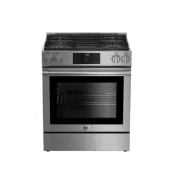
Overview
1 Control panel
2 Wire shelf
3 Front door
4 Handle
5 Bottom part
6 Foot
7 Burner plate
8 Island trim (need to installation see page 39)
Package contents
1. User manual
2. Wire Shelf
Used for roasting and for placing the food to be baked, roasted or cooked in casserole dishes to the desired rack.
3. Proper positioning of the wire shelf on sliding shelves
It is important to position the broil and/or dripping pan on the wire shelves correctly. Slide the broil or the dripping pan completely between the 2 rails and make sure it is stable before putting a dish on it (Please see the following figure).
4. Island trim
Remove the island trim assembly from the packaging taking care to retain the screws required for fixing the island trim to the product. Remove the protective films(if supplied) from the island trim before assembly.
Position the island trim assembly as indicated. Secure the island trim assembly to the appliance with the screws provided. Do not over tighten in order to avoid any damages to the product or island trim.!
Troubleshooting
Oven emits steam when it is in usd.
• It is normal that steam escapes during operation. »> This is not a fault.
Product emits metal noises while heating anti cooling.
• When the metal parts are heated, they may expand and cause noise. »> This is not a fault.
There is no ignition spark.
• No current. »> Check fuses in the fuse box.
There is no gas.
• Main gas valve is closed. »> Open gas valve.
• Gas pipe is bent. »> Install gas pipe properly.
Oven light does not work.
• Oven lamp is defective. »> Replace oven lamp.
• Power is cut. »> Check if there is power. Check the fuses in the fuse box. If necessary, replace or reset the fuses.
Burners are not burning properly or at all.
• Burners are dirty. »> Clean burner components.
• Burners are wet. »> Dry the burner components.
• Burner cap is not mounted safely. »> Mount the burner cap properly.
• Gas valve is closed. »> Open gas valve.
Note Consult the Authorised Service Agent or technician with licence or the dealer where you have purchased the product if you can not remedy the trouble although you have implemented the instructions in this section. Never attempt to repair a defective product yourself.


 As a counter measure against blow out due to fluid overflows at burners, safety mechanism trips and shuts off the gas.