Loading ...
Loading ...
Loading ...
30 • Residen al Standard Gas Water Heater Use and Care Guide
MAINTENANCE
30 • Residen al Standard Gas Water Heater Use and Care Guide
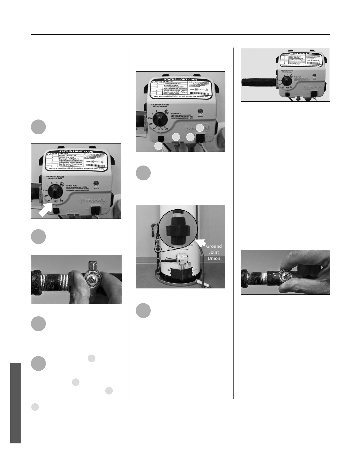
Removing and Replacing the
Gas Control Valve/Thermostat
IMPORTANT: The gas control valve/
thermostat is a standard valve with
wire leads that connect to a thermal
switch.
Removing the Gas Control Valve/
Thermostat:
1
Turn the gas control/tem-
perature knob to the “OFF”
posi on.
Figure 48 - Gas control/valve.
2
Turn off the gas at the
manual shut-off valve on the
gas supply pipe.
Figure 50 - Gas valve in “off” position.
3
Drain the water heater. Refer
to the “Draining and Flushing
the Water Heater” sec on (see
page 28) and follow the procedure.
4
Disconnect the
A
igniter
wire from the igniter lead
wire. Use needle nose pliers
to disconnect the
B
red (+) and white
(-) thermopile wires. Disconnect
C
pilot tube (7/16” wrench) and
D
manifold tube (3/4” wrench) at the
gas control valve/thermostat. NOTE:
L.P. Gas systems use reverse (le -hand)
threads on the manifold tube.
A
C
D
B
Figure 52 - Gas valve connections.
5
Disconnect the ground joint
union in the gas piping.
Disconnect the remaining
pipe from the gas control valve/
thermostat.
Figure 54 - Ground joint union connection.
6
To remove the gas control
valve/thermostat, thread a 4”
sec on of gas pipe into the
inlet and use it to turn theFlame Lock®
Safety System Opera onal Checklist
TROUBLESHOOTING CHART gas control
valve/thermostat (counterclockwise.)
Do not use pipe wrench or equivalent
to grip body. Damage may result,
causing leaks. Do not insert any sharp
objects into the inlet or outlet connec-
ons. Damage to the gas control valve/
thermostat may result.
Figure 56 - Gas control/valve with threaded pipe.
Replacing Gas Control Valve/Thermostat:
To replace the gas control valve/thermo-
stat, reassemble in reverse order. When
replacing the gas control valve/
thermostat, thread a 4” sec on of gas
pipe into the inlet and use it to turn the
gas control valve/thermostat (clockwise.)
DO NOT OVER TIGHTEN, damage may
result.
• Be sure to use approved Tefl on® tape
or pipe joint compound on the gas piping
connec ons and fi ng on
the back of the gas control valve that
screws into tank.
• Be sure to remove the pilot ferrule nut
from the new gas control valve/thermo-
stat.
Figure 58 - Gas valve in “on” position.
• Turn the gas supply on and check for
leaks. Test the water heater by brushing
on an approved noncorrosive
leak detec on solu on. Bubbles forming
indicate a leak. Correct any leak found.
• Be sure tank is completely fi lled with
water before ligh ng and ac va ng the
water heater. Follow the
“Ligh ng Instruc ons” on page 23.
• If addi onal informa on is required,
contact the Service Department at:
1-877-817-6750.
MAINTENANCE
Loading ...
Loading ...
Loading ...