Loading ...
Loading ...
Loading ...
12 • Residen al Standard Gas Water Heater Use and Care Guide
GETTING STARTED
12 • Residen al Standard Gas Water Heater Use and Care Guide
GETTING STARTED
• The vent pipe must be fi rmly at-
tached and sealed to prevent it
from falling out.
• To aid in removing the vent pipe, a
thimble or slip joint may be used.
• The vent pipe must not extend
beyond the inner edge of the
chimney as it may restrict the
space between it and the opposite
wall of the chimney.
Do not terminate the vent pipe in a
chimney that has not been cer fi ed
for this purpose. Some local codes may
prohibit the termina on of vent con-
nectors in a masonry chimney.
Common (combined) ven ng is allow-
able with ver cal Type B vent systems
and lined masonry chimneys as long
as proper dra for the water heater
is established under all condi ons of
opera on. Do not common vent this
water heater with any power vented
appliance.
Ver cal Termina on
NOTICE: The gas vent must be termi-
nated in a ver cal posi on to facilitate
the removal of exhaust gases.
Ver cal exhaust vents must terminate
with a listed cap or other roof assem-
bly and be installed according to their
manufacturer’s instruc ons. An unused
chimney fl ue or masonry enclosure
may be used as a passageway for the
installa on of vent pipe. Do not com-
mon vent this water heater with any
power vented appliance. The follow-
ing fi gures are examples of vent pipe
system installa ons and may or may
not be suitable for your specifi c appli-
ca on. Consult the “Na onal Fuel Gas
Code”, NFPA 54, ANSI Z223.1-current
edi on and local codes.
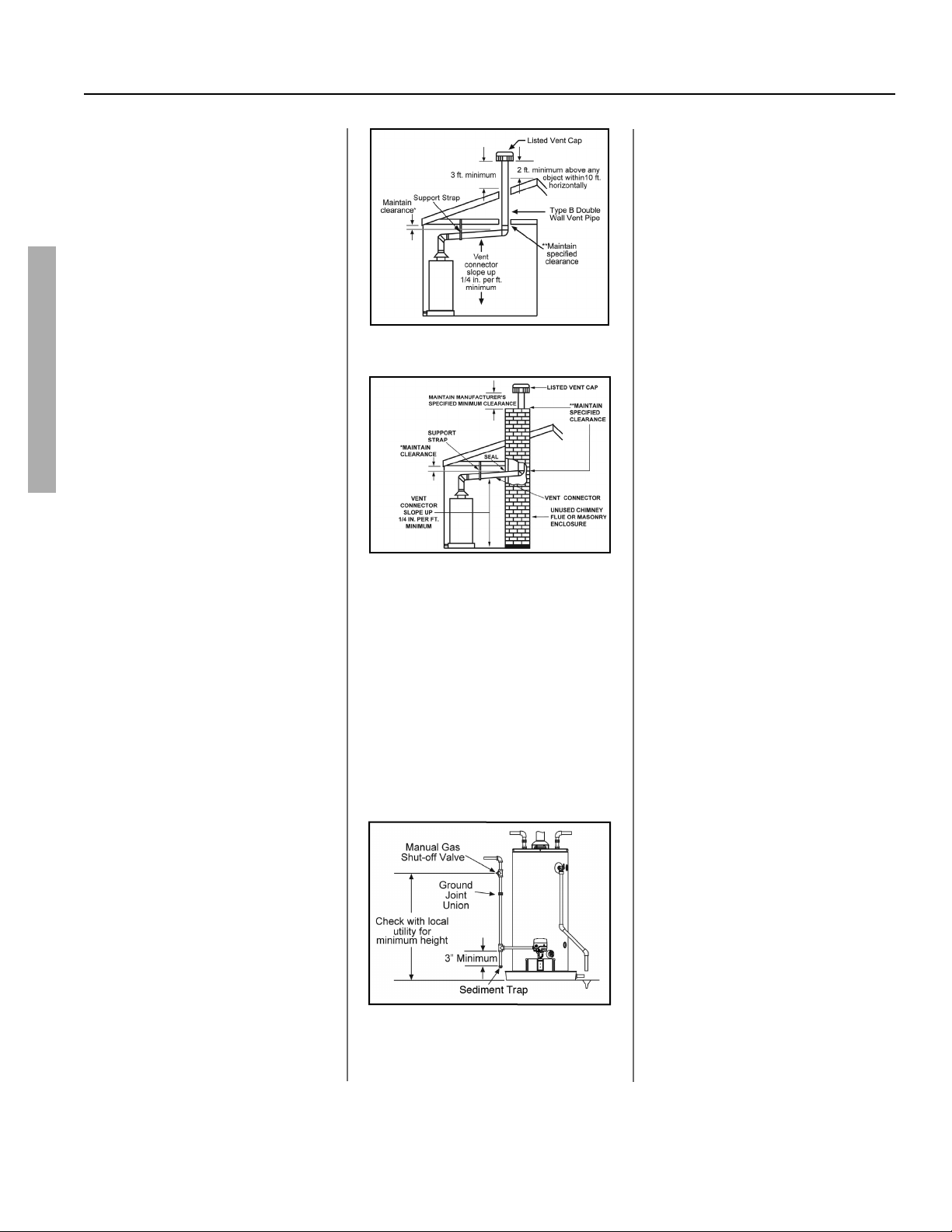
Figure 8 - Vertical gas vent system with type B
double wall vent pipe
Figure 9 - Venting through a chimney with type
B double wall vent pipe
Gas Piping
Gas piping must be installed accord-
ing to local and state codes or, in the
absence of local and state codes,
the “Na onal Fuel Gas Code”, ANSI
Z223.1(NFPA 54)-current edi on.
NOTICE: When installing gas piping,
apply pipe joint compound or Tefl on®
tape approved for fuel gases.
Figure 10 - Gas Piping
1. Install a readily accessible manual
shut-off valve in the gas supply line
as recommended by the local u l-
ity. Know the loca on of this valve
and how to turn off the gas to this
unit.
2. Install a Sediment Trap as shown
in the Gas Piping fi gure below. The
Sediment Trap must be no less than
three inches long for the accumula-
on of dirt, foreign material, and
water droplets.
3. Install a ground joint union be-
tween the gas control valve and
the manual gas shut-off valve. This
is to allow easy removal of the gas
control valve.
4. Turn the gas supply on and check
for leaks. Use a small, so -bristled
brush to apply a hand dishwash-
ing soap and water mixture (1
part soap to 15 parts water) or
children’s soap bubbles to all con-
nec on points of the gas piping.
Saturate all the connec ons and
check for gas leaks (which will ap-
pear as small bubbles). If any leaks
are detected, ghten the appropri-
ate connec on(s) and re-check.
Gas Pressure
NOTICE: When tes ng gas pipes with
a test pressure of more than ½ psi (3.5
kPa), disconnect the gas line at the
manual shut off valve and cap the gas
line. Do not subject the water heater’s
gas control valve or manual shut off
valve to more than ½ psi (3.5 kPa)
pressure for any reason. If you are
pressure tes ng the gas line with test
pressure of ½ psi (3.5 kPa) or less, you
may isolate the water heater from the
gas line by closing the manual shut off
valve.
Loading ...
Loading ...
Loading ...