Loading ...
Loading ...
Loading ...
Residen al Standard Gas Water Heater Use and Care Guide • 19
INSTALLATION
Residen al Standard Gas Water Heater Use and Care Guide • 19
INSTALLATION
4
Check the filter at least every
three months and clean as
necessary. After installation,
the filter may be cleaned by using a
vacuum cleaner with a brush
attachment to remove lint and dust.
NOTE: because the amount of dust and
lint in the air can vary, your filter may
need to be inspected/ cleaned more
often. In some instances, the filter may
need to be removed and washed using
mild hand soap and water to remove
any oily residue. After washing, allow to
dry and properly reinstall.
Step 6:
Connect the Tempera-
ture and Pressure (T&P)
Relief Valve/Pipe
Most T&P Relief Valves are pre-
installed at the factory. In some cases,
they are shipped in the carton and
must be installed in the opening
marked “T&P Relief Valve” and accord-
ing to local codes.
Figure 25 - Temperature and Pressure Relief Valve
WARNING! To avoid serious injury
or death from explosion, install a T&P
Relief Valve according to the following
instruc ons:
1
If the T&P Relief Valve was not
factory installed, install the
new T&P Relief Valve that
came with your water heater. Do not
reuse an old T&P Relief Valve.
• The discharge pipe should be at
least 3/4” inside diameter and
sloped for proper drainage. Install
it to allow complete drainage of
both the T&P Relief Valve and the
discharge pipe.
Figure 26 - Temperature and Pressure Relief
Valve Pipe
• The discharge pipe must not be
smaller than the pipe size of the
T&P Relief Valve. The pipe must
also be able to withstand 250°F
(121°C) without distor on. Use
only copper or CPVC pipe. Do not
use any other type of pipe, such as
PVC, iron, fl exible plas c pipe, or
any type of hose.
• Terminate the discharge pipe a
maximum of six inches above a
fl oor drain or outside the building.
Do not drain the discharge pipe
into the drain pan; instead pipe it
separately to an adequate drain.
In cold climates, terminate the dis-
charge pipe inside the building to
an adequate drain. Outside drains
could freeze and obstruct the
drain line—protect the discharge
pipe from freezing.
• Do not place any valve or other
restric on between the tank and
T&P Relief Valve. Do not cap,
block, plug, or insert any valve
between the T&P Relief Valve and
the end of the discharge pipe. Do
not insert or install any reducer in
the discharge pipe.
Step 7:
Install Shutoff and Ther-
mosta c Mixing Valves
1
If one is not already installed,
install a manual shutoff valve
in the cold water line that
supplies the water heater. Install the
shutoff valve near the water heater so
that it is readily accessible. Only use a
full-fl ow ball or gate valve compa ble
with potable water.
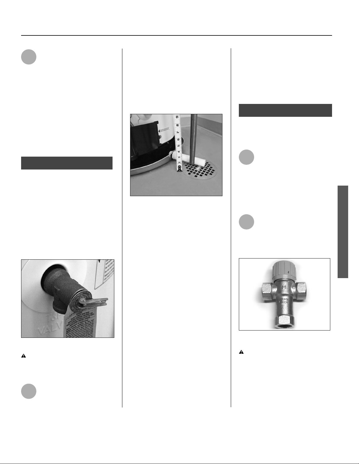
2
Install a Thermosta c Mixing
Valve at each point-of-use (for
example, kitchen sink,
bathroom sink, bath, shower) per the
valve manufacturer’s instruc ons.
Figure 27 - Install Thermostatic Mixing Valves at
each point where hot water will be used.
WARNING! Even if the water
heater’s thermostat is set to a rela-
vely low temperature, hot water can
scald. Install Thermosta c Mixing
Valves at each point-of-use to reduce
the risk of scalding.
Loading ...
Loading ...
Loading ...