Loading ...
Loading ...
Loading ...
13
Connecting to the TV
Choose from the following connections:
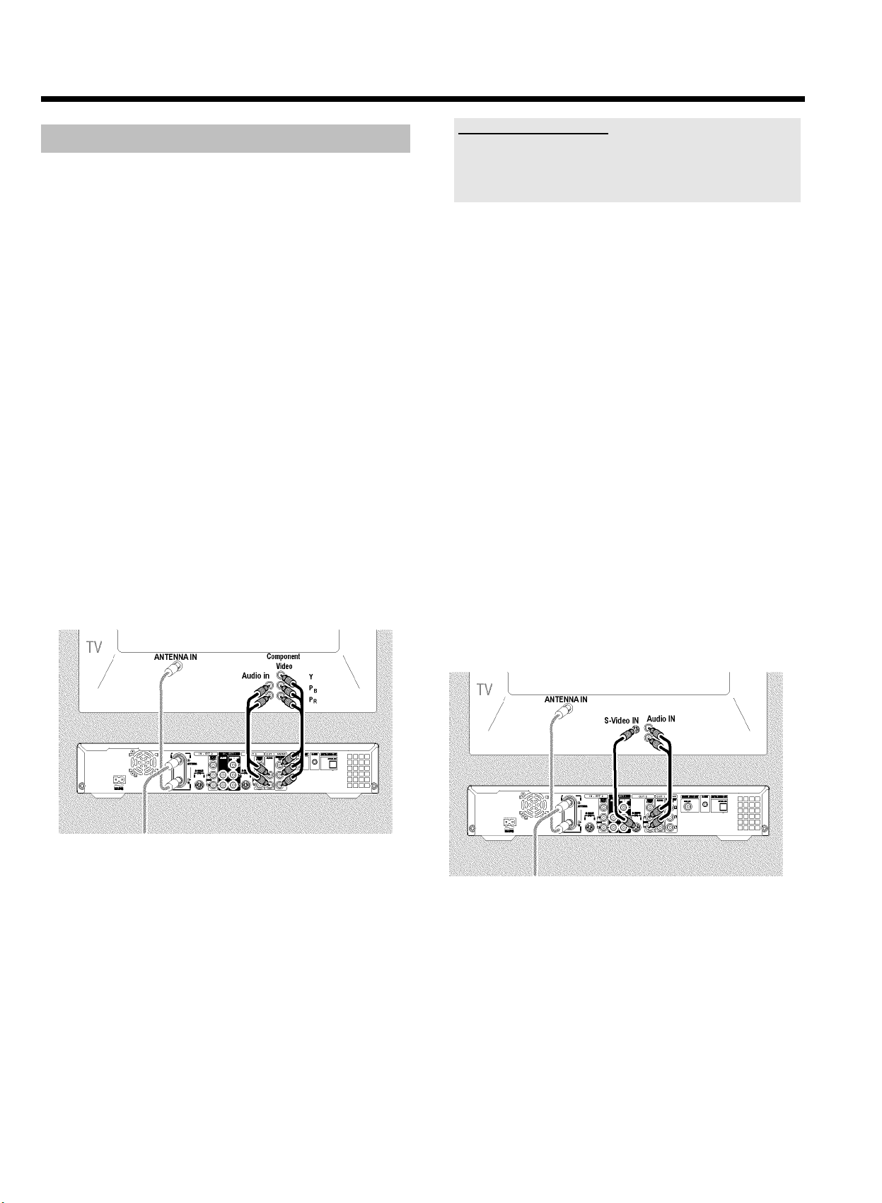
Connection with Component<Video< (Y Pb Pr) cable
Connection with S<videocable
Connection with Video (CVBS) cable
Connection with the antenna cable only
Connection with Component<Video< (Y Pb Pr)
cable
Component Video is the highest quality system for transmitting video
by splitting the video signal into the Y (brightness), U and V (red minus
brightness, blue minus brightness) components. The signals are sent
over separate lines. The plugs for these cables and the corresponding
jacks are usually red, green, and blue.
In addition, the signal can be 'interlaced' or use 'progressive scan.'
Interlaced
The regular video/TV signal is interlaced, i.e. the even and odd lines are
formed as half pictures in an alternate fashion.
Progressive scan
With progressive scan, each picture is structured (approx. 50/60 times
per second depending on the TV system) as a complete picture, i.e. the
even and odd lines are formed together. Disruptive picture flickering is
avoided as is the case with 100 Hz TV devices.
1 Use the Component Video (Y Pb Pr) cable and connect one end to
the red, blue, green COMPONENT VIDEO-OUT1 jacks at the
back of the DVD Recorder and the other end to the Component
Video In jacks of the TV.
2 If your TV set is equipped with a 'progressive scan' jack, please use
this jack. (Usually called 'Video In Y Pb Pr'. Please see your TV's
instruction manual).
Please note the color order
The colors of the jacks on the DVD Recorder must match those on the
TV (red-red/blue-blue/green-green). If they are not matched properly,
this could cause the color of the picture to be reversed or there could be
no picture at all.
3 Use an audio cable and plug one end into the AUDIO L/R (OUT
1) jack at the back of the DVD Recorder (next to COMPONENT
VIDEO-OUT1 ) and the other into the red/white Audio In jacks of
the TV (usually called Audio in', 'AV in'. Please see your TV's
instruction manual).
O Read the next chapter 'Connecting additional devices' on how
to connect additional devices (satellite receivers,
videorecorders,...) to the input-/output jacks.
Then, read the chapter on 'Connecting to the AC-outlet.
Connecting with a S<Video (Y/C) cable
This connecting cable, also known as the SVHS cable, is used to
transmit the brightness signal (Y signal) and color signal (C signal)
separately. This mini DIN jack/plug is also called a Hosiden jack/plug.
1 Use a S-Video (SVHS) cable and plug one end into the S-VIDEO
(Y/C)-OUT2 jack at the back of the DVD Recorder and the other
end into the S-Video (SVHS) In jack of the TV (usually called
'S-Video in' or 'SVHS in'. See your TV's instruction manual).
2 Use an audio (cinch) cable and plug one end into the red/white
cinch jack AUDIO L/R (OUT 2) at the back of the DVD
Recorder (next to S-VIDEO (Y/C)-OUT2 ) and the other into
the corresponding red/white audio input jack of the TV (usually
called Audio in', 'AV in'. See your TV's instruction manual).
O Read the next chapter 'Connecting additional devices' on how
to connect additional devices (satellite receivers,
videorecorders,...) to the input-/output jacks.
Then, read the chapter on 'Connecting to the AC-outlet'.
Connecting the DVD recorder
Loading ...
Loading ...
Loading ...