Loading ...
Loading ...
Loading ...

INSTALLATION
WALL MOUNTED SALAMANDER AND
SHELF ASSY FOR 36”, 48” AND 60” WIDE UNITS
1. Each gas appliance shall be located with respect to building construction and
Other Equipment so as to permit access to the appliance. Such access and
Clearance is necessary for service and cleaning.
2. A welded wall mounted Salamander and shelf assembly, which includes two
(2) hi-hat supports, one (1) lower support angle, one (1) upper support angle,
one (1) rear shelf panel, one (1) shelf, and one Salamander bottom panel.
Also hardware required for attachment of components.
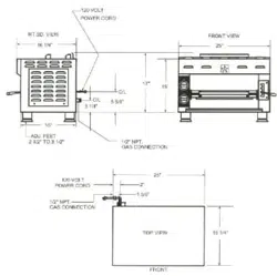
3. Review pages 4 & 5 as a reference for mounting the wall mount kit. Drilled
Holes are required in both the upper and lower Lt. to Rt. Supports (ADDED
BY OTHERS), before any mounting can take place. NOTE!!!! Installer is
Responsible for mounting hardware as well as insuring that the wall
mount assembly once positioned in place can support a minimum of 200
lbs.
4. After the wall mount unit has been installed, remove the second screw back
from the front top piece (1) from the left side (1) from the right side. Slide the
Salamander in between the flanges of the wall mount assembly. By keeping
the front flush with the Wall mount brackets, the bottom mounting holes
should line up. With the (4) ¼ -20 x 1” bolts supplied from the factory, secure
the Salamander to the Bottom flanges of the wall mount assembly.
5. Attach the upper shelf angle to the top rear support with (2) sheet metal
screws provided. Attach the lower shelf angle to the bottom rear support
with (2) sheet Metal screws provided.
6. Next position and attach the shelf back panel to the (2) angles added in step
(6).
7. Attach the shelf with (3) 10-24 machine screws provided. Make adjustments
as necessary.
8. Attach the bottom panel and use the (4) plug buttons to seal the ½” holes
9. Replace the (2) screws removed in step (5) assembly is complete.
PAGE 9
Loading ...
Loading ...
Loading ...