Loading ...
Loading ...
Loading ...
40
adjacent to the AC cord inlet. If the fuse is blown (best veried
using an ohm meter), contact your qualied Classé dealer for
replacement fuse based on the unit conguration below.
Mains voltage: 100-120VAC
Fuse type:
IEC time lag, low breaking capacity
Rating: 2AL 250V
Mains voltage: 200-240VAC
Fuse type:
IEC time lag, high breaking capacity
Rating: 1.25AH 250V
3 One speaker or subwoofer seems not to be playing.
P If the problem occurs with all inputs, check the interconnecting
cables between the preamp and the power amp. Also check the
speaker wires for secure connections.
P Check the balance control setting by pressing MENU on the
front panel, and then verify the balance control setting is not
turning one channel o or reducing its output.
P If the problem occurs for a subwoofer only, make sure it is active
on the conguration assigned to this source button or the one
that has been independently selected.
P Check the interconnect cables between the source component
and the Delta PRE.
4 The IR remote control does not seem to function.
P Ensure that there are no obstacles between the IR remote and the
IR sensor.
P Check the orientation and if necessary, replace the batteries in
the remote control.
P Be sure the IR sensor is not awash in direct sunlight.
5 There is a hum coming out of the speakers.
P If you are using single-ended interconnects, make sure they are
not placed alongside any AC power cords. Also make sure that
they are not too long – long single-ended interconnecting cables
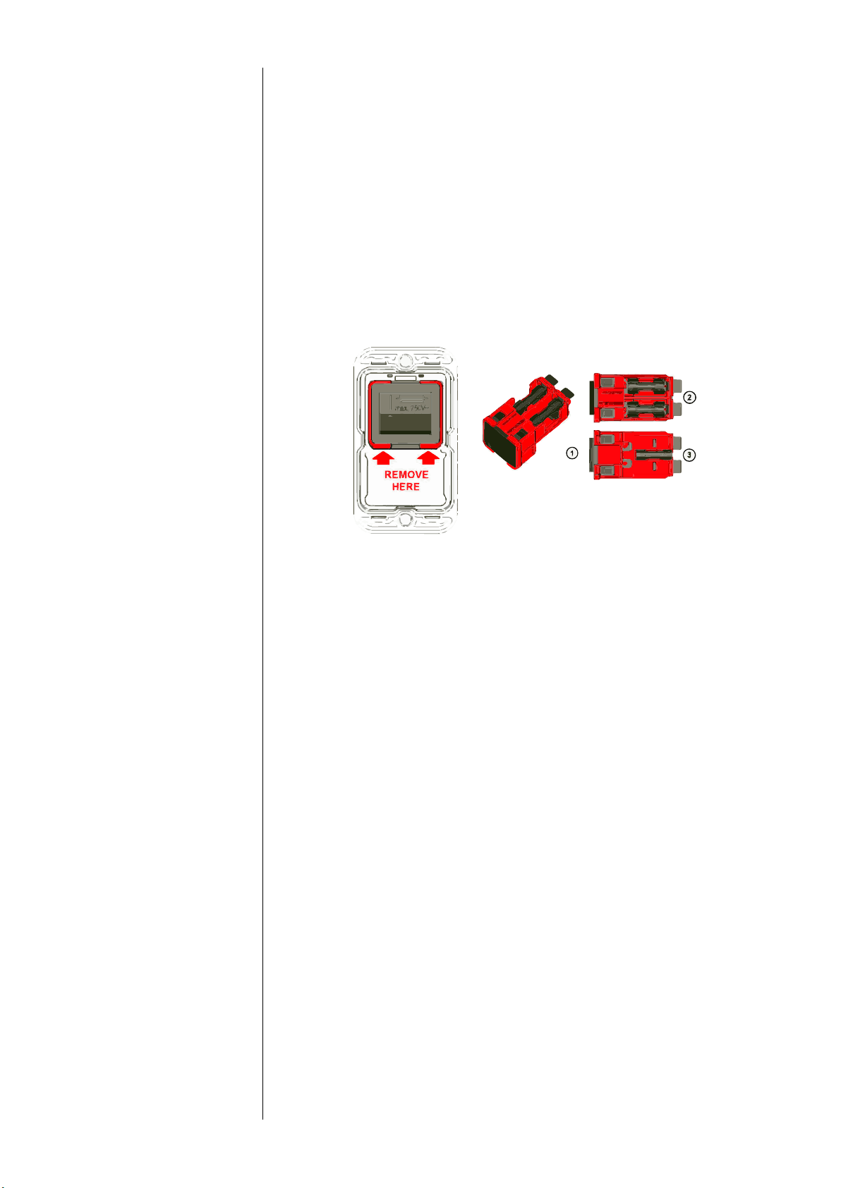
Removal of the combined switch / fuse holder unit
An additional fuse mark on the switch indicates the fuses holders behind the
switch. The red frame shows the outline of the removable unit.
With a simple tool like a Swiss Army knife or a screwdriver No 1 or smaller the
unit (1) can be removed from the lter. On the topside (2) behind the switch
there are two fuse holders for each live connection. On the bottom side (3) is
a clip to carry an additional spare fuse.
Loading ...
Loading ...
Loading ...