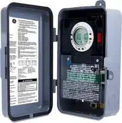
User Manual Digital Box Timer Switch
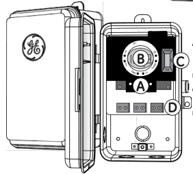
A. Indicator Lights
Orange light — Indicates timer is powered
Green light — Indicates load is powered
B. Digital Timer (shown in detail below)
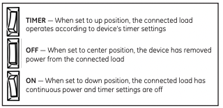
C. Operation Mode Switch (shown in detail below)
D. Connection Terminals
Environmental ratings
Ambient temperature: –40° to 130° F Humidity: 0-95% RH, non-condensing.
Wiring connections
Screw clamp terminals for up to two 8AWG wires per position. For supply connections, use 8AWG or larger wires suitable for at least 105° C. Use copper conductors only.
Read and follow all instructions and warranty information prior to use to ensure protection to connected equipment and warranty compliance.
• Pliers
• Wire cutters
• Hammer
• Phillips-head screwdriver
• Flat-head screwdriver

Pre-installation
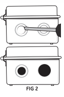
Before installation, follow the instructions below to remove knockouts to route wiring to connection terminals. Knockouts may be made 1/2in. or 3/4in.
For 1/2in. knockout
- Place small-blade screwdriver into inner ring of knockout circle [FIG 2].
- Tap down lightly with the screwdriver to punch the 1/2in. knockout loose.
For 3/4in. knockout
- Create 1/2in. knockouts as instructed.
- Grip outer ring of knockout circle with pliers.
- Gently twist and pull to remove outer ring and form 3/4in. knockout.
Choose a suitable mounting location
Mounting the box for drywall
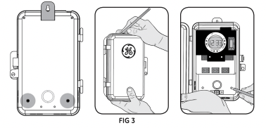
- Hold the box in place and use the three holes highlighted to mark position on the mounting surface [FIG 3].
- Drill a 3/16in. hole for the drywall anchors at each marked location.
- Insert an anchor in each hole and gently tap the open end of anchor with a hammer until the anchor is almost flush with the wall.
- Mount the box to the anchors using the supplied screws.
Mounting the box for solid surface
- Hold the box in place and use the three holes highlighted to mark position on the mounting surface [FIG 3].
- Drill a 3/32in. hole at each marked location.
- Mount the box to the surface using the supplied screws.
IMPORTANT! Always close the rainproof door after use.
Wiring
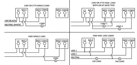
Connect 120VAC/60Hz power supply following provided wiring diagram.
Initial setup
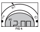
Before setting the current time and programming timers, press and release the reset button with a toothpick [FIG 4]. This will clear the memory. The display will begin flashing “12:00”. Press and release the clock button to stop the display from flashing.
IMPORTANT - This will erase all stored timers
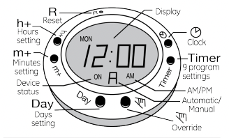
Clock setting
- Press and hold the clock button through all steps.
- Press the “H+” button to set the hour noting AM and PM.
- Press the “M+” button to set the minutes
- Press the “day” button to select the day of the week.
- Release the clock button.
The colon flashes to indicate the clock is operating.
Timer programming
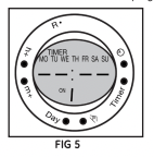
- Press the “timer” button. “TIMER 1 ON -- : --” appears [FIG 5].
- Adjust the time to the desired ON setting using the “H+” and “M+” buttons.
- Press the “day” button to select the day(s) for the timer to be activated (see “Multiple-Day Groups” below for day options).
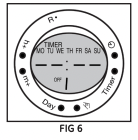
- Press the “timer” button. “TIMER 1 OFF -- : --” appears [FIG 6].
- Adjust the time to the desired OFF setting using the “H+” and “M+” buttons.
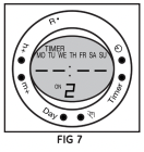
- Press the “timer” button again to set up to 8 additional ON/OFF programs following the previous steps [FIG 7].
- Press “clock” button when all programs are set to return to the time display.
Muliple-day groups
In addition to daily programs, the “day” button allows multiple-day combinations. Available groups include:
Monday – Sunday. (Default). Monday, Wednesday, Friday
Monday – Friday. Tuesday, Thursday, Saturday
Saturday – Sunday. Monday – Wednesday.
Monday – Saturday. Thursday – Saturday.
Countdown
Repeatedly press “timer” button to cycle through all nine programs until “ON C 00:00” displays. Press override button to select ON/OFF function.
- "ON C” – Connected device is ON during the countdown, turns OFF when countdown expires [FIG 8].
- "OFF C” – Connected device is OFF during the countdown, turns ON when countdown expires [FIG 6].
- Set countdown time using the “H+” and “M+” buttons [FIG 10].
- Press clock button to store the setting. Timer will return to current time display.
- To activate the countdown, press clock and override buttons simultaneously. ‘C’ will flash to indicate timer is counting down.
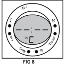
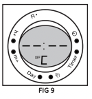
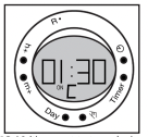
FIG 10 (timer set to turn devices off in 1 hour and 30 minutes)
During countdown:
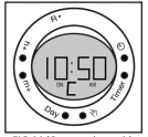
FIG 11 (Current time with countdown running)
- Press override button to pause the countdown. ‘C’ will stop flashing to indicate timer has paused counting down.
- Press clock button to change the display to time or countdown mode – countdown continues to run in either display [FIG 11].
- Press clock and override buttons simultaneously to reset the countdown to its programmed time.
- Note: If a countdown overlaps a scheduled ON time, that program will not operate until its next scheduled occurrence.
Canceling settings
- Press the “timer” button until the ON time of the program you want to cancel displays.
- Press the “H+” button until “-- : --” displays.
- Press the “timer” button and repeat this process to cancel the programmed OFF time.
- Repeat as necessary to cancel any unneeded settings.
Deactivating settings
- To deactivate a program without deleting it, press the “timer” button until the desired ON time displays.
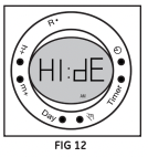
- Press the override button. “H1:dE” [FIG 12] displays to indicate the program will not operate until manually activated.
- Press the “timer” button again and repeat the previous steps to deactivate the programmed OFF time and any additional settings.
- Repeat these steps to manually reactivate the program(s).
Auto/manual operation
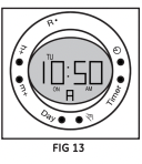
To switch from automatic (default) to manual operation, press the override button until the “A” on the screen disappears – approx. 5 seconds [FIG 13]. Use the override button to turn the connected device ON/OFF. – Timer settings will not operate. Press and hold the override button until the “A” appears on the screen to reactivate stored timer settings.
Override during auto operation
Press the override button at any time to manually turn the connected device ON or OFF. The status of the device is conveniently identified by the ON/OFF indicator in the lower-left section of the display screen.
Random ON/OFF
Increase security by creating a lived-in appearance using the random function to automatically vary programmed ON/OFF times by up to 30 minutes. At least one timer program must be set and active to use the random feature.
- Press the clock button.
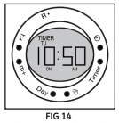
- Press “day” and “H+” buttons simultaneously. “Timer” flashes in the upper-left portion of the screen to indicate random ON/OFF is activated [FIG 14].
- Press “day” and “H+” buttons simultaneously again to cancel random operation.
Daylight saving time adjustment
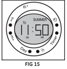
Press “H+” and “M+” buttons simultaneously to automatically add one hour to the set time. “Summer” appears at the top of the display screen to indicate time is adjusted for daylight saving time [FIG 15].
Press “H+” and “M+” buttons simultaneously again to return to standard time.
Battery backup
In the event of a power failure, a built-in battery backup maintains timer settings. The battery recharges when power is restored.
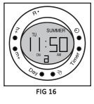
To prevent modification of any clock or timer settings, press the clock button for 5 seconds. Stored settings function as scheduled. An “a” at the bottom of the display screen indicates all buttons are locked [FIG 16].
Solid “a” – Automatic mode.
Flashing “a” – Manual mode.
To unlock the buttons, press the clock button for 5 seconds again.
WARNING
• RECOMMEND INSTALLATION BY LICENSED ELECTRICIAN.
CAUTION: RISK OF ELECTRIC SHOCK
• MORE THAN ONE DISCONNECT SWITCH MAY BE REQUIRED TO DE-ENERGIZE THE DEVICE BEFORE SERVICING.
• HIGH VOLTAGE (THERE MAY BE MORE THAN ONE SOURCE OF SUPPLY) DISCONNECT ALL POWER SOURCES BEFORE SERVICING.
• USE COPPER CONDUCTORS ONLY.
• CLOSE THE COVER AFTER USE.
• TIGHTEN CONNECTIONS TO 25 LBF-IN.
• USE CORRECT GAUGE WIRE (8-14 AWG) BASED ON LOCAL ELECTRICAL CODE OF AT LEAST 80°C RATING (SINGLE CORE IN 8 AWG).
• RAINTIGHT, APPROVED FOR OUTDOOR USE.
• WIRE STRIP LENGTH 1/2”.
GROUNDING
• NATIONAL ELECTRICAL CODE REQUIRES THAT GROUNDING MUST BE CONTINUOUS AND IN PROPER ELECTRICAL CONTACT IN ALL GROUNDING CONDUCTORS, METALLIC CONDUITS AND GROUNDING TERMINALS.