Home
Bookmarks
Home
Binder
Binder LIT MK 720 User Manual
Page 166
Binder LIT MK 720 MK 720-liter dynamic climate chambers for rapid temperature changes
User Manual - Page 166
For LIT MK 720.
PDF File Manual
,
173 pages
,
Read Online
|
Download pdf file
More photos
1. Safety
1.1 Personnel Qualification
1.2 Operating manual
1.3 Legal considerations
1.4 Structure of the safety instructions
1.4.1 Signal word panel
1.4.2 Safety alert symbol
1.4.3 Pictograms
1.4.4 Word message panel structure
1.5 Localization / position of safety labels on the chamber
1.6 Type plate
1.7 General safety instructions
1.7.1 Notes on the installation site
1.7.2 Notes on loading and operation
1.7.3 Notes on handling CO2
1.7.4 Notes on handling nitrogen when using it as inert gas
1.7.5 Precautions when handling gas cylinders
2. Intended use
2.1 Use
2.1.1 EUCAR Hazard levels â Overview
2.2 General requirements for the chamber load
2.3 Tests with EUCAR hazard level up to max. 3
2.3.1 Requirements for the chamber load
2.3.2 Operation with the max. Expectation of an EUCAR event with hazard level 3
2.4 Tests with EUCAR hazard level 4 to 6
2.4.1 Requirements for the chamber load
2.4.2 Detection and secure inclusion of an event within the battery test chamber by immanent safety with a defined load (max. one single 18650 cell with LIT MK 240, max. three 18650 cells with LIT MK 720)
2.4.3 Detection and safe inclusion of an event within the battery test chamber by additional operator-provided measures with a defined load
2.5 Medical devices
2.6 Personnel Requirements
2.7 Installation site requirements and ambient conditions
3. Foreseeable Misuse
4. Residual Risks
5. Operator responsibility, documentation, and measures
5.1 Risk assessment
5.2 Employee training and protocols
5.3 Operating instructions
5.4 Protective equipment
5.5 Standard Operating Procedures (SOPs)
5.6 Testing and maintenance
5.7 System logbook
5.8 Operation log
6. Testing
6.1 Objective of testing
6.2 Scope of the tests
6.2.1 Testing before initial commissioning
6.2.2 Tests of technical ventilation systems, extinguishing systems, gas warning devices, inerting devices, devices, protective systems or safety, control or regulating devices, and other technical devices for explosion protection
6.2.3 Inspection after changes requiring review
6.2.4 Recurring tests
6.3 Proof of tests
7. Chamber description
7.1 Manufacturer's safety plan: Protective measures and equipment
7.2 Chamber overview
7.3 Safety module on the right side of the chamber
7.4 Lateral control panel
7.5 Rear power switch
7.6 Instrument panel
7.7 Rear chamber view
7.8 Gas detection
7.9 CO2 fire suppression device (can be triggered automatically and manually)
7.9.1 Automatic triggering of the CO2 fire suppression device
7.9.2 After triggering of the CO2 fire suppression device
7.10 Mechanical door lock
7.11 Exhaust port with reversible pressure relief flap
8. Completeness of delivery, transportation, storage, and installation
8.1 Unpacking, and checking equipment and completeness of delivery
8.2 Guidelines for safe lifting and transportation
8.3 Storage
8.4 Location of installation and ambient conditions
9. Installation and connections
9.1 Connecting the CO2 pressurized gas cylinder
9.2 Inertization connections for customer systems
9.3 Installation of the voltage and frequency changer (chambers with voltage and frequency changer)
9.4 Electrical connection
9.4.1 Information on connecting the battery test chamber
9.4.2 Connecting the voltage and frequency changer (for chambers equipped with a voltage and frequency changer)
10. Functional overview of the MB2 chamber controller
10.1 Operating functions in normal display
10.2 Display views: Normal display, program display, chart-recorder display
10.3 Controller icons overview
10.4 Operating modes
10.5 Controller menu structure
10.5.1 Main menu
10.5.2 âSettingsâ submenu
10.5.3 âServiceâ submenu
10.6 Principle of controller entries
10.7 Performance during and after power failures
10.8 Performance when opening the door
11. Commissioning
11.1 Preparing and activating the general safety devices
11.1.1 Inserting the CO2 pressurized gas cylinder
11.1.2 Activating the gas detection system
11.1.3 Connection of the coil connector on the CO2 pressurized gas cylinder
11.1.4 Function test of the valve
11.1.5 Connecting the CO2 flushing line (high-pressure hose)
11.2 Commissioning an operator-provided inertization
11.3 Handling the safety devices during operation
11.4 Turning on the chamber
11.5 Controller settings upon start up
12. Set-point entry in âFixed valueâ operating mode
12.1 Set-point entry through the âSetpointsâ menu
12.2 Direct setpoint entry via Normal display
12.3 Special controller functions via operation lines
13. Notification and alarm functions
13.1 Alarms via indicator light with integrated buzzer
13.1.1 Connections and forwarding of notifications and alarms to customer systems
13.2 Notification and alarm messages overview on the MB2 chamber controller
13.2.1 Notifications
13.2.2 Alarm messages
13.2.3 State of alarm
13.2.4 Resetting an alarm, list of active alarms
13.2.5 Activating / deactivating the audible alarm (alarm buzzer) of the MB2 controller
14. Behavior when/after triggering of the CO2 fire suppression device
15. Temperature safety devices
15.1 Over temperature protective device (class 1)
15.2 Temperature limiter class 2
15.3 Overtemperature safety controller (adjustable temperature limiter class 2
15.3.1 Safety controller modes
15.3.2 Setting the safety controller
15.3.3 Message and measures in the state of alarm
15.3.4 Function check
15.4 Over/under temperature safety device class 2 (option)
16. Timer program: stopwatch function
16.1 Starting a timer program
16.1.1 Performance during program delay time
16.2 Stopping a running timer program
16.2.1 Pausing a running timer program
16.2.2 Cancelling a running timer program
16.3 Performance after the end of the program
17. Time programs
17.1 Starting an existing time program
17.1.1 Performance during program delay time
17.2 Stopping a running time program
17.2.1 Pausing a running time program
17.2.2 Cancelling a running time program
17.3 Performance after the end of the program
17.4 Creating a new time program
17.5 Program editor: program management
17.5.1 Deleting a time program
17.6 Section editor: section management
17.6.1 Add a new program section
17.6.2 Copy and insert or replace a program section
17.6.3 Deleting a program section
17.7 Value entry for a program section
17.7.1 Section duration
17.7.2 Set-point ramp and set-point step
17.7.3 Special controller functions via operation lines
17.7.4 Setpoint entry
17.7.5 Tolerance range
17.7.6 Repeating one or several sections within a time program
17.7.7 Saving the time program
18. Week programs
18.1 Starting an existing week program
18.2 Cancelling a running week program
18.3 Creating a new week program
18.4 Program editor: program management
18.4.1 Deleting a week program
18.5 Section editor: section management
18.5.1 Add a new program section
18.5.2 Copy and insert or replace a program section
18.5.3 Deleting a program section
18.6 Value entry for a program section
18.6.1 Set-point ramp and set-point step modes
18.6.2 Weekday
18.6.3 Start time
18.6.4 Setpoint entry
18.6.5 Special controller functions via operation lines
19. User management
19.1 Authorization levels and password protection
19.2 Log in
19.3 Log out
19.4 User change
19.5 Password assignment and password change
19.5.1 Password change
19.5.2 Deleting the password for an individual authorization level
19.5.3 New password assignment for âServiceâ or âAdminâ authorization level when the password function was deactivated
19.6 Activation code
20. General controller settings
20.1 Selecting the controllerâs menu language
20.2 Setting date and time
20.3 Selecting the temperature unit
20.4 Display configuration
20.4.1 Adapting the display parameters
20.4.2 Touchscreen calibration
20.5 Network and communication
20.5.1 Serial interfaces
20.5.2 Ethernet
20.5.2.1 Configuration
20.5.2.2 Display of MAC address
20.5.3 Web server
20.5.4 E-Mail
20.6 USB menu: Data transfer via USB interface
20.7 Turning off the interior lighting automatically
21. General information
21.1 Service contact page
21.2 Current operating parameters
21.3 Event list
21.4 Technical chamber information
22. Chart recorder display
22.1 Views
22.1.1 Show and hide legend
22.1.2 Switch between legend pages
22.1.3 Show and hide specific indications
22.1.4 History display
22.2 Setting the parameters
23. Notes on refrigerating operation
24. Anti-condensation protection via operation line
25. Zero-voltage switching outputs via operation lines
26. Options
26.1 APT-COM⢠4 Multi Management Software (option)
26.1.1 APT-COM⢠4 Basic Edition
26.2 RS485 interface (option)
26.3 Data logger kit (option)
26.4 Analog outputs for temperature (option)
26.5 Object temperature display with flexible Pt 100 temperature sensor (option)
26.6 Compressed air connection (option)
27. Cleaning and decontamination
27.1 Cleaning the battery test chamber following normal operation
27.2 Cleaning the battery test chamber after triggering of the CO2 fire suppression device
27.3 Decontamination / chemical disinfection
28. Maintenance: inspection, maintenance, troubleshooting, repair, testing
28.1 General information, personnel qualification
28.2 Maintenance intervals, service
28.3 Inspections
28.4 Simple troubleshooting
28.5 Sending the chamber back to BINDER GmbH
29. Disposal
29.1 Disposal of the transport packing
29.2 Decommissioning
29.3 Disposal of the chamber in the Federal Republic of Germany
29.4 Disposal of the chamber in the member states of the EU except for the Federal Republic of Germany
29.5 Disposal of the chamber in non-member states of the EU
30. Technical description
30.1 Factory calibration and adjustment
30.2 Over-current protection
30.3 Definition of usable volume
30.4 Technical data
30.5 Equipment and options (extract)
30.6 Accessories and spare parts (extract)
30.7 Dimensions
31. Certificates and declarations of conformity
31.1 EU Declaration of Conformity
31.2 Certificate for the GS mark of conformity of the âDeutsche Gesetzliche Unfallversicherung e.V.â (German Social Accident Insurance) DGUV
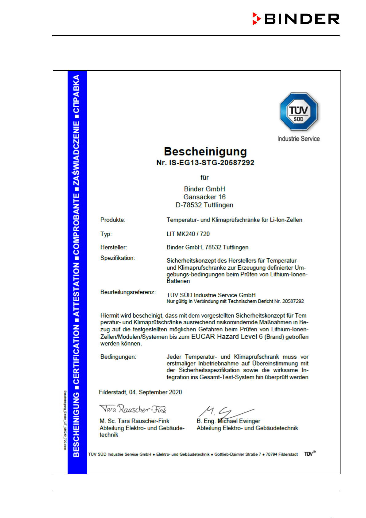
31.3 Safety concept certificate from TÃV Süd
32. Contamination clearance certificate
32.1 For chambers located outside the USA and Canada
32.2 For chambers located in the USA and Canada
Leere Seite
Page 166/173
Page 1
Page 2
Page 3
Page 4
Page 5
Page 6
Page 7
Page 8
Page 9
Page 10
Page 11
Page 12
Page 13
Page 14
Page 15
Page 16
Page 17
Page 18
Page 19
Page 20
Page 21
Page 22
Page 23
Page 24
Page 25
Page 26
Page 27
Page 28
Page 29
Page 30
Page 31
Page 32
Page 33
Page 34
Page 35
Page 36
Page 37
Page 38
Page 39
Page 40
Page 41
Page 42
Page 43
Page 44
Page 45
Page 46
Page 47
Page 48
Page 49
Page 50
Page 51
Page 52
Page 53
Page 54
Page 55
Page 56
Page 57
Page 58
Page 59
Page 60
Page 61
Page 62
Page 63
Page 64
Page 65
Page 66
Page 67
Page 68
Page 69
Page 70
Page 71
Page 72
Page 73
Page 74
Page 75
Page 76
Page 77
Page 78
Page 79
Page 80
Page 81
Page 82
Page 83
Page 84
Page 85
Page 86
Page 87
Page 88
Page 89
Page 90
Page 91
Page 92
Page 93
Page 94
Page 95
Page 96
Page 97
Page 98
Page 99
Page 100
Page 101
Page 102
Page 103
Page 104
Page 105
Page 106
Page 107
Page 108
Page 109
Page 110
Page 111
Page 112
Page 113
Page 114
Page 115
Page 116
Page 117
Page 118
Page 119
Page 120
Page 121
Page 122
Page 123
Page 124
Page 125
Page 126
Page 127
Page 128
Page 129
Page 130
Page 131
Page 132
Page 133
Page 134
Page 135
Page 136
Page 137
Page 138
Page 139
Page 140
Page 141
Page 142
Page 143
Page 144
Page 145
Page 146
Page 147
Page 148
Page 149
Page 150
Page 151
Page 152
Page 153
Page 154
Page 155
Page 156
Page 157
Page 158
Page 159
Page 160
Page 161
Page 162
Page 163
Page 164
Page 165
Page 166
Page 167
Page 168
Page 169
Page 170
Page 171
Page 172
Page 173
Contents
Table of Contents
Search
Previous
Next
Troubleshooting
Bookmarks
Loading ...
Loading ...
Loading ...
MK LIT
(E
5
)
01/20
21
page
166
/
17
2
31.3
S
afety
concept
cert
ificate fro
m TÜV Süd
Loading ...
Loading ...
Loading ...
File type: PDF
File name: 75207361_lit-mk-720.pdf
File size: 8.04 MB
File Language: English
Pages: 173
Author: Binder
Published:
2021-08-19
Updated: 2023-05-22
Download File
Table of Contents
×
1. Safety
7
1.1 Personnel Qualification
7
1.2 Operating manual
7
1.3 Legal considerations
7
1.4 Structure of the safety instructions
8
1.4.1 Signal word panel
8
1.4.2 Safety alert symbol
8
1.4.3 Pictograms
9
1.4.4 Word message panel structure
9
1.5 Localization / position of safety labels on the chamber
10
1.6 Type plate
10
1.7 General safety instructions
11
1.7.1 Notes on the installation site
12
1.7.2 Notes on loading and operation
13
1.7.3 Notes on handling CO2
14
1.7.4 Notes on handling nitrogen when using it as inert gas
15
1.7.5 Precautions when handling gas cylinders
15
2. Intended use
16
2.1 Use
16
2.1.1 EUCAR Hazard levels â Overview
17
2.2 General requirements for the chamber load
18
2.3 Tests with EUCAR hazard level up to max. 3
18
2.3.1 Requirements for the chamber load
18
2.3.2 Operation with the max. Expectation of an EUCAR event with hazard level 3
19
2.4 Tests with EUCAR hazard level 4 to 6
19
2.4.1 Requirements for the chamber load
19
2.4.2 Detection and secure inclusion of an event within the battery test chamber by immanent safety with a defined load (max. one single 18650 cell with LIT MK 240, max. three 18650 cells with LIT MK 720)
21
2.4.3 Detection and safe inclusion of an event within the battery test chamber by additional operator-provided measures with a defined load
21
2.5 Medical devices
22
2.6 Personnel Requirements
22
2.7 Installation site requirements and ambient conditions
22
3. Foreseeable Misuse
23
4. Residual Risks
24
5. Operator responsibility, documentation, and measures
27
5.1 Risk assessment
27
5.2 Employee training and protocols
27
5.3 Operating instructions
28
5.4 Protective equipment
28
5.5 Standard Operating Procedures (SOPs)
28
5.6 Testing and maintenance
28
5.7 System logbook
29
5.8 Operation log
29
6. Testing
30
6.1 Objective of testing
30
6.2 Scope of the tests
30
6.2.1 Testing before initial commissioning
30
6.2.2 Tests of technical ventilation systems, extinguishing systems, gas warning devices, inerting devices, devices, protective systems or safety, control or regulating devices, and other technical devices for explosion protection
31
6.2.3 Inspection after changes requiring review
32
6.2.4 Recurring tests
32
6.3 Proof of tests
32
7. Chamber description
33
7.1 Manufacturer's safety plan: Protective measures and equipment
33
7.2 Chamber overview
35
7.3 Safety module on the right side of the chamber
37
7.4 Lateral control panel
38
7.5 Rear power switch
39
7.6 Instrument panel
39
7.7 Rear chamber view
40
7.8 Gas detection
41
7.9 CO2 fire suppression device (can be triggered automatically and manually)
43
7.9.1 Automatic triggering of the CO2 fire suppression device
44
7.9.2 After triggering of the CO2 fire suppression device
44
7.10 Mechanical door lock
44
7.11 Exhaust port with reversible pressure relief flap
45
8. Completeness of delivery, transportation, storage, and installation
46
8.1 Unpacking, and checking equipment and completeness of delivery
46
8.2 Guidelines for safe lifting and transportation
47
8.3 Storage
47
8.4 Location of installation and ambient conditions
47
9. Installation and connections
49
9.1 Connecting the CO2 pressurized gas cylinder
49
9.2 Inertization connections for customer systems
49
9.3 Installation of the voltage and frequency changer (chambers with voltage and frequency changer)
51
9.4 Electrical connection
52
9.4.1 Information on connecting the battery test chamber
52
9.4.2 Connecting the voltage and frequency changer (for chambers equipped with a voltage and frequency changer)
53
10. Functional overview of the MB2 chamber controller
55
10.1 Operating functions in normal display
56
10.2 Display views: Normal display, program display, chart-recorder display
57
10.3 Controller icons overview
58
10.4 Operating modes
60
10.5 Controller menu structure
61
10.5.1 Main menu
62
10.5.2 âSettingsâ submenu
63
10.5.3 âServiceâ submenu
63
10.6 Principle of controller entries
64
10.7 Performance during and after power failures
64
10.8 Performance when opening the door
65
11. Commissioning
65
11.1 Preparing and activating the general safety devices
65
11.1.1 Inserting the CO2 pressurized gas cylinder
65
11.1.2 Activating the gas detection system
66
11.1.3 Connection of the coil connector on the CO2 pressurized gas cylinder
67
11.1.4 Function test of the valve
67
11.1.5 Connecting the CO2 flushing line (high-pressure hose)
68
11.2 Commissioning an operator-provided inertization
69
11.3 Handling the safety devices during operation
70
11.4 Turning on the chamber
70
11.5 Controller settings upon start up
71
12. Set-point entry in âFixed valueâ operating mode
72
12.1 Set-point entry through the âSetpointsâ menu
72
12.2 Direct setpoint entry via Normal display
73
12.3 Special controller functions via operation lines
73
13. Notification and alarm functions
75
13.1 Alarms via indicator light with integrated buzzer
75
13.1.1 Connections and forwarding of notifications and alarms to customer systems
76
13.2 Notification and alarm messages overview on the MB2 chamber controller
77
13.2.1 Notifications
77
13.2.2 Alarm messages
78
13.2.3 State of alarm
78
13.2.4 Resetting an alarm, list of active alarms
79
13.2.5 Activating / deactivating the audible alarm (alarm buzzer) of the MB2 controller
79
14. Behavior when/after triggering of the CO2 fire suppression device
80
15. Temperature safety devices
80
15.1 Over temperature protective device (class 1)
80
15.2 Temperature limiter class 2
81
15.3 Overtemperature safety controller (adjustable temperature limiter class 2
81
15.3.1 Safety controller modes
81
15.3.2 Setting the safety controller
82
15.3.3 Message and measures in the state of alarm
83
15.3.4 Function check
83
15.4 Over/under temperature safety device class 2 (option)
84
16. Timer program: stopwatch function
85
16.1 Starting a timer program
85
16.1.1 Performance during program delay time
85
16.2 Stopping a running timer program
86
16.2.1 Pausing a running timer program
86
16.2.2 Cancelling a running timer program
86
16.3 Performance after the end of the program
86
17. Time programs
87
17.1 Starting an existing time program
87
17.1.1 Performance during program delay time
88
17.2 Stopping a running time program
88
17.2.1 Pausing a running time program
88
17.2.2 Cancelling a running time program
88
17.3 Performance after the end of the program
88
17.4 Creating a new time program
89
17.5 Program editor: program management
89
17.5.1 Deleting a time program
90
17.6 Section editor: section management
91
17.6.1 Add a new program section
92
17.6.2 Copy and insert or replace a program section
92
17.6.3 Deleting a program section
93
17.7 Value entry for a program section
94
17.7.1 Section duration
94
17.7.2 Set-point ramp and set-point step
95
17.7.3 Special controller functions via operation lines
96
17.7.4 Setpoint entry
97
17.7.5 Tolerance range
98
17.7.6 Repeating one or several sections within a time program
99
17.7.7 Saving the time program
99
18. Week programs
100
18.1 Starting an existing week program
100
18.2 Cancelling a running week program
100
18.3 Creating a new week program
101
18.4 Program editor: program management
102
18.4.1 Deleting a week program
103
18.5 Section editor: section management
104
18.5.1 Add a new program section
105
18.5.2 Copy and insert or replace a program section
105
18.5.3 Deleting a program section
106
18.6 Value entry for a program section
106
18.6.1 Set-point ramp and set-point step modes
106
18.6.2 Weekday
107
18.6.3 Start time
107
18.6.4 Setpoint entry
108
18.6.5 Special controller functions via operation lines
108
19. User management
109
19.1 Authorization levels and password protection
109
19.2 Log in
112
19.3 Log out
113
19.4 User change
113
19.5 Password assignment and password change
114
19.5.1 Password change
114
19.5.2 Deleting the password for an individual authorization level
116
19.5.3 New password assignment for âServiceâ or âAdminâ authorization level when the password function was deactivated
117
19.6 Activation code
118
20. General controller settings
119
20.1 Selecting the controllerâs menu language
119
20.2 Setting date and time
119
20.3 Selecting the temperature unit
121
20.4 Display configuration
121
20.4.1 Adapting the display parameters
121
20.4.2 Touchscreen calibration
122
20.5 Network and communication
123
20.5.1 Serial interfaces
123
20.5.2 Ethernet
124
20.5.2.1 Configuration
124
20.5.2.2 Display of MAC address
125
20.5.3 Web server
125
20.5.4 E-Mail
126
20.6 USB menu: Data transfer via USB interface
127
20.7 Turning off the interior lighting automatically
128
21. General information
128
21.1 Service contact page
128
21.2 Current operating parameters
129
21.3 Event list
130
21.4 Technical chamber information
130
22. Chart recorder display
131
22.1 Views
131
22.1.1 Show and hide legend
131
22.1.2 Switch between legend pages
131
22.1.3 Show and hide specific indications
132
22.1.4 History display
132
22.2 Setting the parameters
135
23. Notes on refrigerating operation
136
24. Anti-condensation protection via operation line
137
25. Zero-voltage switching outputs via operation lines
138
26. Options
139
26.1 APT-COM⢠4 Multi Management Software (option)
139
26.1.1 APT-COM⢠4 Basic Edition
139
26.2 RS485 interface (option)
139
26.3 Data logger kit (option)
139
26.4 Analog outputs for temperature (option)
140
26.5 Object temperature display with flexible Pt 100 temperature sensor (option)
140
26.6 Compressed air connection (option)
141
27. Cleaning and decontamination
141
27.1 Cleaning the battery test chamber following normal operation
142
27.2 Cleaning the battery test chamber after triggering of the CO2 fire suppression device
143
27.3 Decontamination / chemical disinfection
144
28. Maintenance: inspection, maintenance, troubleshooting, repair, testing
145
28.1 General information, personnel qualification
145
28.2 Maintenance intervals, service
146
28.3 Inspections
147
28.4 Simple troubleshooting
147
28.5 Sending the chamber back to BINDER GmbH
150
29. Disposal
150
29.1 Disposal of the transport packing
150
29.2 Decommissioning
151
29.3 Disposal of the chamber in the Federal Republic of Germany
151
29.4 Disposal of the chamber in the member states of the EU except for the Federal Republic of Germany
152
29.5 Disposal of the chamber in non-member states of the EU
154
30. Technical description
154
30.1 Factory calibration and adjustment
154
30.2 Over-current protection
154
30.3 Definition of usable volume
154
30.4 Technical data
155
30.5 Equipment and options (extract)
157
30.6 Accessories and spare parts (extract)
158
30.7 Dimensions
159
31. Certificates and declarations of conformity
161
31.1 EU Declaration of Conformity
161
31.2 Certificate for the GS mark of conformity of the âDeutsche Gesetzliche Unfallversicherung e.V.â (German Social Accident Insurance) DGUV
164
31.3 Safety concept certificate from TÃV Süd
166
32. Contamination clearance certificate
167
32.1 For chambers located outside the USA and Canada
167
32.2 For chambers located in the USA and Canada
170
Leere Seite
173
Search:
×
Search