INSTRUCTION MANUAL
PORTABLE AIR CONDITIONER
Thank you for choosing BLACK+DECKER!
PLEASE READ BEFORE RETURNING THIS PRODUCT FOR
ANY REASON.
If you have a question or experience a problem with your BLACK+DECKER
purchase, go to www.blackanddecker.com/instantanswers
If you can’t find the answer or do not have access to the Internet, call
844-299-0879 from 10:30 a.m. to 6:30 p.m. EST Mon. - Fri. to speak with an
agent. Please have the catalog number available when you call.
SAVE THIS MANUAL FOR FUTURE REFERENCE.
CATALOG NUMBER
BPACT08WT
BPACT10WT
BPACT12WT
BPACT12HWT
BPACT14WT
BPACT14HWT

Page 2
Thank you for purchasing our
BLACK+DECKER product. This
easy-to-use manual will guide you
in getting the best use of your air
conditioner.
Remember to record the model
and serial numbers. They are on a
label on the rear.
Staple your receipt to your manual.
You will need it to obtain warranty service.
Model number
Serial number
Date of purchase
PRODUCT REGISTRATION
CONTENTS
SAFETY INFORMATION
Important Safety Instructions ..........................................................................................................................................3-4
Grounding Instructions ......................................................................................................................................................... 5
LCDI Power Cord and Plug ..................................................................................................................................6
Safety Guidelines .................................................................................................................................................... 7
Operating Conditions ............................................................................................................................................ 8
SET UP & USE
Parts & Features .......................................................................................................................................................................9
Installation Guide .................................................................................................................................................. 10
Window Slider Kit Installation ............................................................................................................................11
Exhaust Hose Installation ....................................................................................................................................12
Control Panel ...........................................................................................................................................................13
Operating from the Control Panel .............................................................................................................13-14
Operating from the Remote Control .............................................................................................................. 15
Remote Control ................................................................................................................................................16-19
Water Drainage ...............................................................................................................................................20-21
CLEANING & CARE .............................................................................................................................................22
TROUBLESHOOTING & WARRANTY
Before You Call For Service ..............................................................................................................................23
Customer Service .................................................................................................................................................. 23
Troubleshooting ....................................................................................................................................................24
Limited Warranty ...................................................................................................................................................................25
Page 3
SAFETY INFORMATION
IMPORTANT SAFETY INSTRUCTIONS
1. To reduce risk of injury, read this guide before using the appliance.
2. Air conditioner must be connected to proper electrical outlet with the correct
electrical outlet with the correct electrical supply.
3. Proper grounding must be ensured to reduce the risk of shock and re. DO NOT
CUT OR REMOVE THE GROUNDING PRONG. If you do not have a three-prong
electric receptacle outlet in the wall, have a certied electrician install the proper
receptacle. The wall receptacle MUST be properly grounded.
4. Do not operate air conditioner if power cord is frayed or otherwise damaged.
Avoid using it if there are any cracks or abrasion damage along the length, plug
connector or if the unit malfunctions or is damaged in any manner. Contact an
authorized service technician for examination, repairs or adjustments.
5. DO NOT USE AN ADAPTER OR AN EXTENSION CORD.
6. Do not block airow around the air conditioner. The exhaust hose should be free
of any obstructions.
7. Always unplug the air conditioner before servicing or moving the unit.
8. Do not install or use the air conditioner in any area where the atmosphere
contains combustible gases or where the atmosphere is oily or sulphurous. Avoid
any chemical coming in contact with your air conditioner.
9. Do not place any object on the top of the unit.
10. Never operate the air conditioner without lters in place.
11. Do not use the air conditioner near a bathtub, shower or wash basin.
12. This appliance is not intended for use by persons (including children) with
reduced physical sensory or mental capabilities or lack of experience &
knowledge, unless they have been given supervision or instruction concerning
use of the appliance by a person responsible for their safety.
13. Children should be supervised to ensure that they do not play with the appliance.
14. If the SUPPLY CORD is damaged, it must be replaced by the manufacturer, a
service agent or similarly qualied persons in order to avoid a hazard.
15. The air conditioner shall be installed in accordance with national wiring
regulations.
WARNING
WARNING - Hazards or unsafe
practices which COULD result in
severe personal injury or death
DANGER
DANGER - Immediate hazards
which WILL result in severe
personal injury or death
CAUTION
CAUTION - Hazards or unsafe
practices which COULD result in
minor personal injury
WARNING
When using electrical appliances, basic safety precautions
should be followed, including the following

Page 4
HANDLING ALKALINE BATTERIES
1. Should uid from the battery accidentally get into your eyes, there is a threat
of loss of eyesight, do not rub them. Immediately rinse your eyes with clean tap
water and then consult a physician immediately.
2. Do not put the battery in a re, expose it to heat, dismantle or modify it. If the
insulation or safety valve is damaged, the battery may leak uid, overheat or
explode.
3. Do not insert the battery with the poles reversed. Doing so may cause some
abnormality or a short and the battery may leak uid, overheat or explode.
4. Keep the battery out of the reach of children. If the battery is swallowed, contact
a physician immediately.
5. If the alkali uid gets in your mouth, rinse your mouth with water and contact a
physician immediately.
6. If the alkali uid gets on your skin or clothes, it may burn your skin, thoroughly
rinse the affected area with tap water.
7. Do not mix new and old batteries or other makes of batteries. The different
attributes may cause the battery to leak uid, overheat or explode.
8. This battery was not made to be recharged. Recharging this battery may damage
the insulation or internal structure and may cause the battery to leak uid,
overheat or explode.
9. Do not damage or remove the label on the exterior of the battery. Doing so may
cause the battery to short, leak uid, overheat or explode.
10. Do not drop, throw or expose the battery to extreme impact. Doing so may cause
the battery to leak uid, overheat or explode.
11. Do not alter the shape of the battery. If the insulation or safety valve is damaged,
the battery may leak uid, overheat or explode.
12. Immediately remove batteries when they have lost all power. Leaving the
batteries in the unit for a long time may cause the batteries to leak uid, overheat
or explode due to gas that is generated by the batteries.
13. Remove the batteries from the unit when not using the unit for an extended
period of time. The batteries may leak uid, overheat or explode due to gas that is
generated by the batteries.
14. Do not apply solder directly to the batteries. The heat may cause the batteries to
leak uid, overheat or explode.
15. Do not get the batteries wet. Doing so may cause the batteries to overheat.
16. Store batteries someplace out of direct sunlight where the temperature and
humidity are not high. Not doing so may cause the batteries to leak uid,
overheat or explode. Also, it may cause the life and performance of the batteries
to decline.
17. Follow the regulations of the local government when disposing of these batteries.
18. NEVER mix alkaline, standard (carbon-zinc), rechargeable (nickel-cadmium)
batteries with this product.
SAVE THESE INSTRUCTIONS
HOUSEHOLD USE ONLY
WARNING
When handling alkaline batteries, basic safety precautions
should be followed, including the following
SAFETY INFORMATION
Page 5
GROUNDING INSTRUCTIONS
ELECTRICAL REQUIREMENTS
In the event of malfunction or breakdown, grounding provides a path of least
resistance for electric current to reduce the risk of electric shock. The appliance
must be connected to a cord having an equipment-grounding conductor and
a grounding plug. The plug must be plugged into an appropriate outlet that
is properly installed and grounded in accordance with all local codes and
ordinances.
DANGER - Improper connection of the equipment grounding conductor can
result in a risk of electric shock. The conductor with insulation having an outer
surface that is green with or without yellow stripes is the equipment grounding
conductor. If repair or replacement of the cord or plug is necessary, do not
connect the equipment-grounding conductor to a live terminal. Check with
a qualified electrician or service person if the grounding instructions are not
completely understood, or if in doubt as to whether the appliance is properly
grounded. Do not modify the plug connected to the appliance – if it will not fit
the outlet, have a proper outlet installed by a qualified electrician.
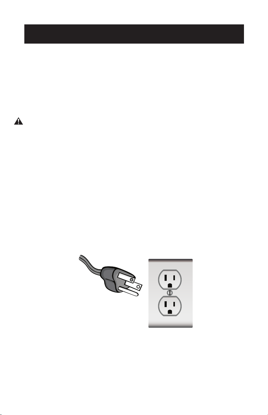
FOR GROUNDED, CORD-CONNECTED APPLIANCE RATED LESS THAN 15A AND
INTENDED FOR USE ON A NOMINAL 120V SUPPLY CIRCUIT
The appliance is for use on a nominal 120V circuit and should be connected to a
grounding outlet that looks like the one illustrated below. The use of a temporary
adapter is not recommended.
SAFETY INFORMATION
Page 6
SAFETY INFORMATION
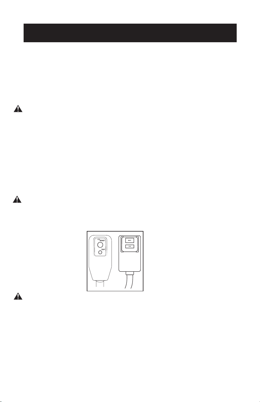
LCDI POWER CORD AND PLUG
This air conditioner is equipped with an LCDI (Leakage Current Detection and
Interruption) power cord that is required by UL. This power supply cord contains
state-of-the-art electronics that sense leakage current. If the cord is damaged
and leakage occurs, power will be disconnected from the unit.
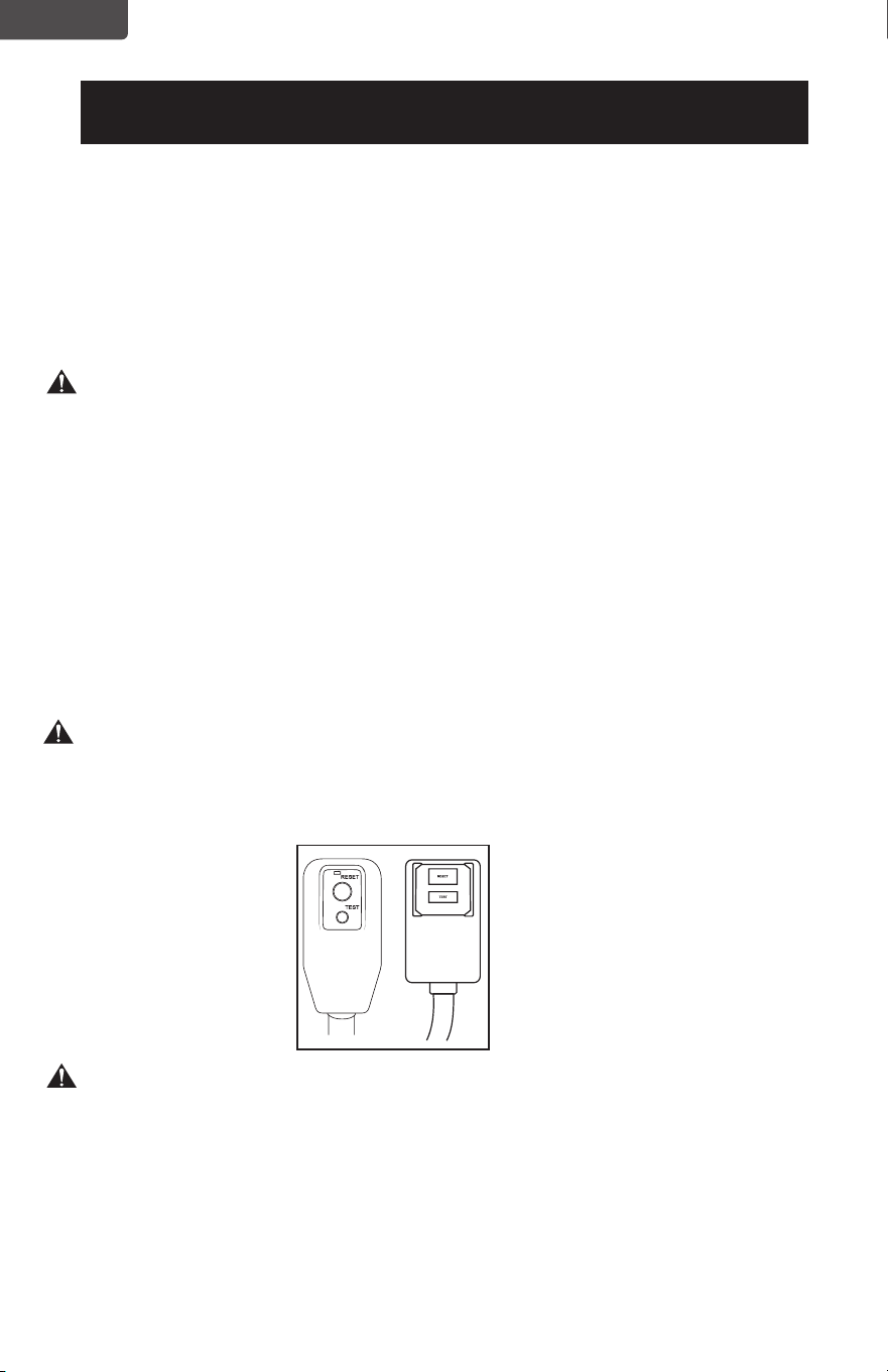
The test and reset buttons on the LCDI Plug are used to check if the plug is
functioning properly.
WARNING: Test LCDI before each use.
To test the plug:
1. Plug power cord into a grounded 3-prong outlet.
2. Press RESET (on some units a green light will turn on).
3. Press the TEST button, the circuit should trip and cut all power to the air
conditioner (on some units green light may turn off).
4. Press the RESET button for use. You will hear a click and the A/C is ready for use.
5. The power supply cord must be replaced if it fails to trip when the TEST button is
pressed and the unit fails to reset.
NOTE:
• Do not use this device to turn the unit on or o.
• Always make sure the reset button is pushed in for correct operation.
WARNING:
• The power supply cord must be replaced if it fails to reset when either the test
button is pushed, or it cannot be reset.
• If power supply cord is damaged, it cannot be repaired.
• It must be replaced by one obtained from the product manufacturer.
WARNING- RISK OF FIRE
It is important the plug fits tightly into the wall outlet.
If the plug does not fit securely and appears loose, it should not be used.
Have a licensed electrician replace the receptacle.
Page 7
SAFETY GUIDELINES
WARNING: To prevent injury to the user or other people and property
damage, the following instructions must be followed. Incorrect
operation due to ignoring of instructions may cause harm or
damage.
• Your air conditioner
should be used in such a
way that it is protected
from moisture. e.g.
condensation, splashed
water, etc. Do not place or
store your air conditioner
where it can fall or be
pulled into water or any
other liquid. Unplug
immediately.
• Always transport your air
conditioner in a vertical
position and stand on a
stable, level surface during
use.
• Turn off the product when
not in use.
• Always use the switch on
the control panel to start or
shut off the unit.
• Always contact a qualied
person to carry out
repairs. If the supply cord
is damaged it must be
repaired by a qualied
technician.
• Keep an air path of at least
12 inches all around the unit
from walls, furniture and
curtains.
• If the air conditioner is
knocked over during use,
turn off the unit and unplug
from the power supply
immediately.
• Do not operate your air
conditioner in a wet room
such as a bathroom or
laundry room.
• Do not touch the unit with
wet or damp hands or when
barefoot.
• Do not press the buttons
on the control panel with
anything other than your
ngers.
• Do not remove any xed
covers. Never use this
appliance if it is not working
properly, or if it has been
dropped or damaged.
• Never use the plug to start
and stop the unit.
• Always use the switch on the
control panel to start or shut
off the unit.
• Do not cover or obstruct the
inlet or outlet grilles.
• Do not use hazardous
chemicals to clean or come
into contact with the unit.
Do not use the unit in the
presence of inammable
substances or vapor such as
alcohol, insecticides, petrol,
etc.
• Do not allow children
to operate the unit
unsupervised.
• Do not use this product for
functions other than those
described in this instruction
manual.
• Use the unit in the
recommended room size.
8,000 BTU up to 350 sq. ft.
10,000 BTU up to 450 sq. ft.
12,000 BTU up to 550 sq. ft.
14,000 BTU up to 700 sq. ft.
• Locate the unit where
furniture cannot obstruct
the air ow.
• Keep blinds/curtains
drawn.
• Keep the lters clean.
• Keep doors and windows
closed to keep cool air in
and warm air out.
SAFETY INFORMATION

OPERATING CONDITIONS
The air conditioner must be operated within the temperature range indicated below:
NOTE: Unit performance may be affected when in use outside of these operating temperatures.
MODE ROOM TEMPERATURE
COOL 64˚F (18˚C) ~ 76˚F (24˚C)
(Maximum humidity:75.2°F / 24°C )
DRY 64˚F (18˚C) ~ 95˚F (35˚C)
HEAT (Heat models BPACT12HWT and
BPACT14HWT only)
45˚F (7˚C) ~ 81˚F (27˚C)
SAFETY INFORMATION
Page 8
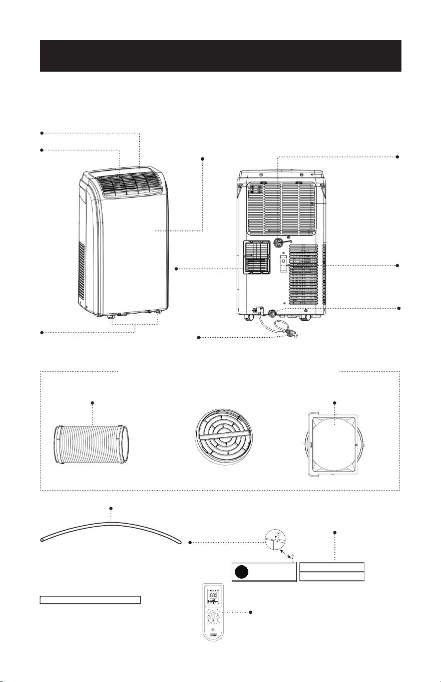
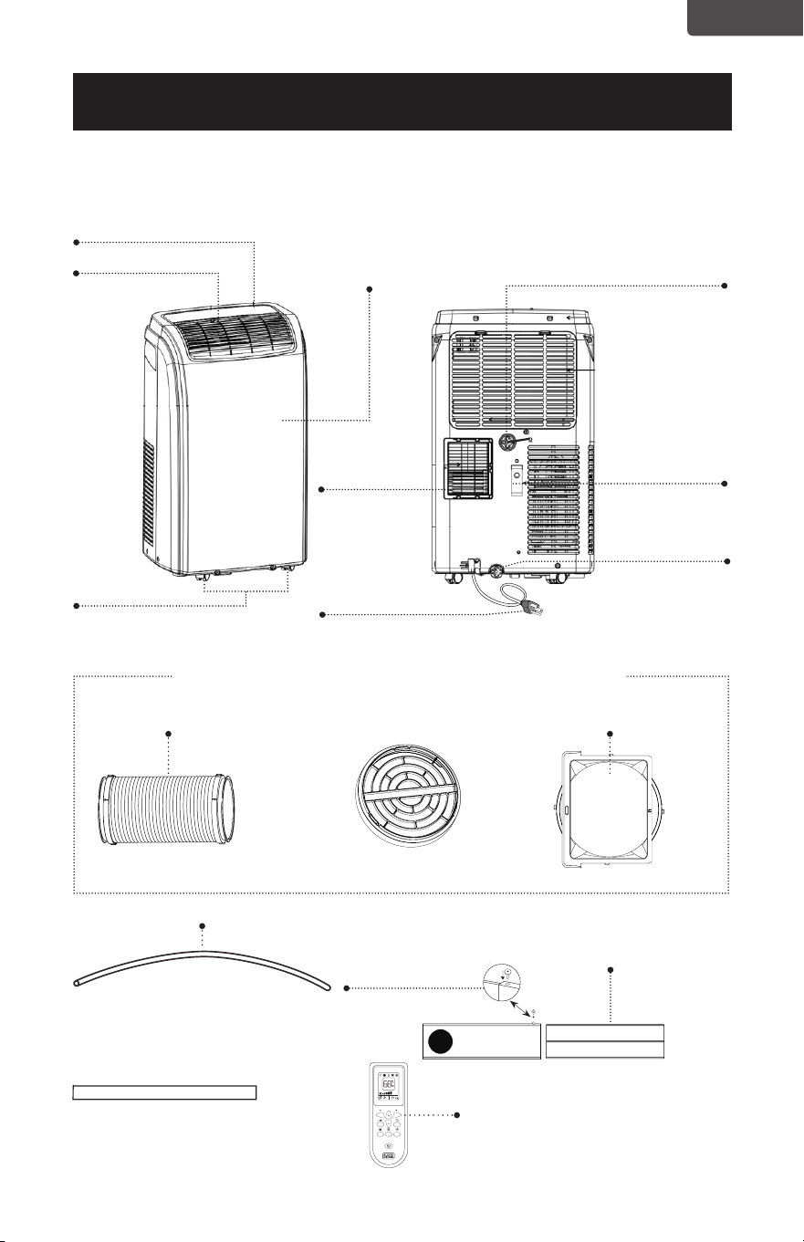
PARTS & FEATURES
Power cord holder
Power Cord
Condensation Drain
Dehumidication Drain
Control Panel
Front Panel
Louver
Air Exhaust Hose Hose Inlet
Hose Outlet
Drain Hose
3.3 feet long
0.6 inch diameter
Remote Control
Foam Seal
2 Locking Screws
SET UP & USE
Window Bracket
Hose outlet and inlet are pre-assembled to the hose
Page 9
Air Exhaust
Hose Housing
Outlet
Caster Wheels

Page 10
INSTALLATION GUIDE
LOCATION
• The air conditioner should be placed on a rm oor to minimize noise and
vibration. For safe and secure positioning, place the unit on a smooth, level
oor strong enough to support the unit.
• The unit has casters to aid placement, but it should be rolled on smooth, at
surfaces. Use caution when rolling on carpet surfaces. Do not attempt to roll
the unit over objects.
• The unit must be placed within reach of a properly rated grounded socket.
• Never place any obstacles around the air inlet or outlet of the unit.
• A removal air-conditioner shall be installed in the at and empty place all
around. Don’t block the air outlet, and the required distance around should
be at least 80cm required distance above should be at least 50cm.
SUGGESTED TOOLS FOR WINDOW KIT INSTALLATION
• Screwdrivers (medium size Phillips)
• Tape measure or ruler
• Knife or scissors
• Saw (In the event that the window kit needs to be cutdown in size because the
window is too narrow for direct installation)
SET UP & USE
Page 11
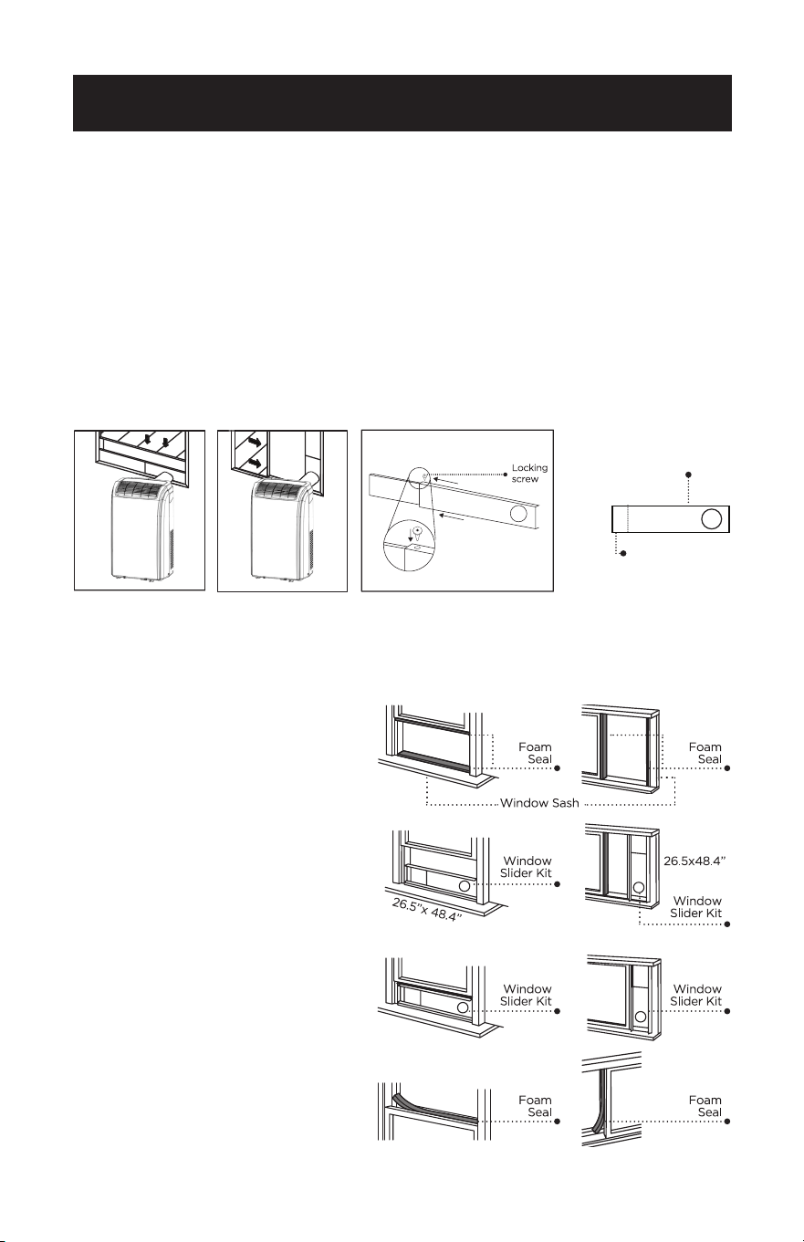
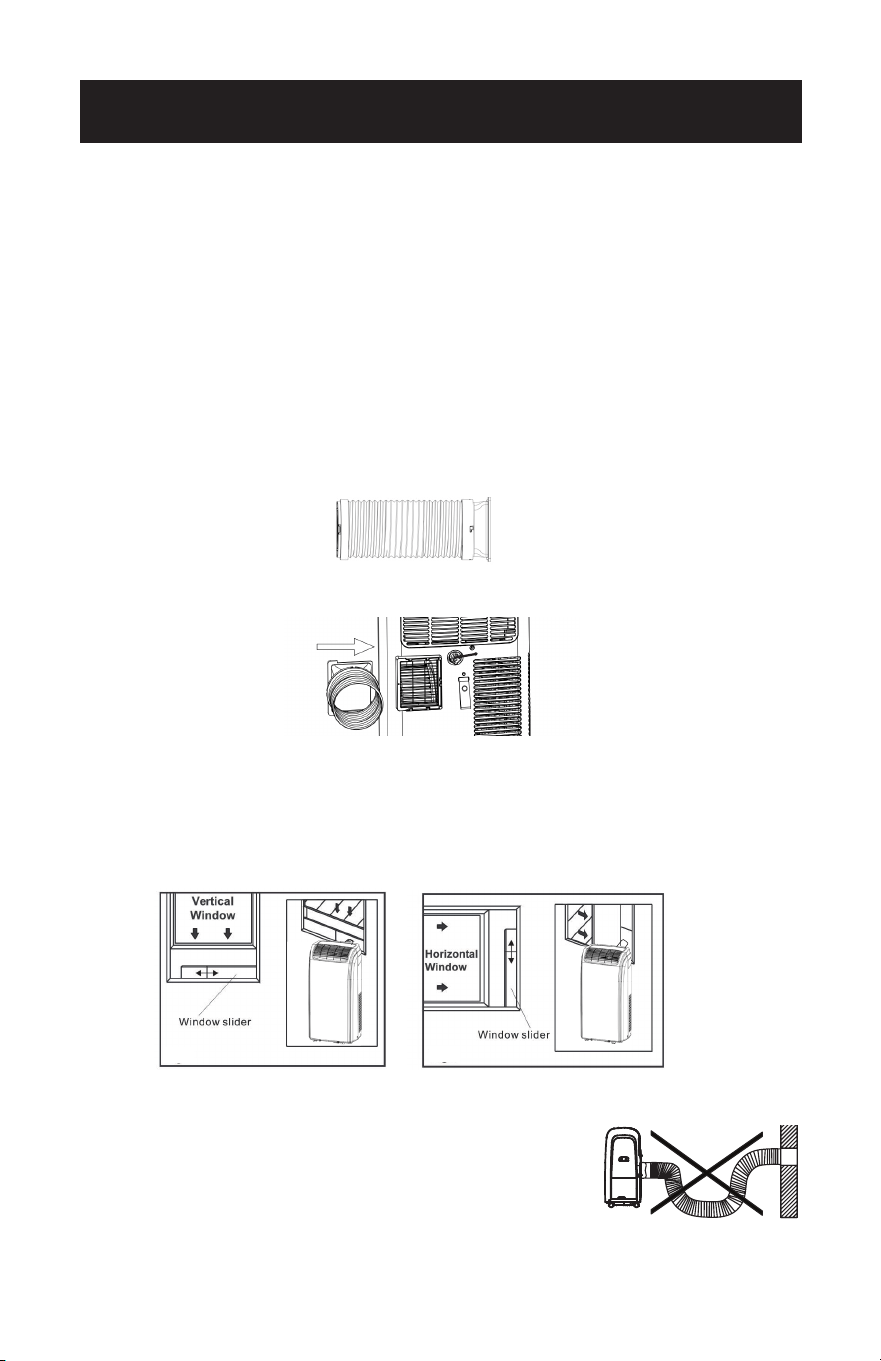
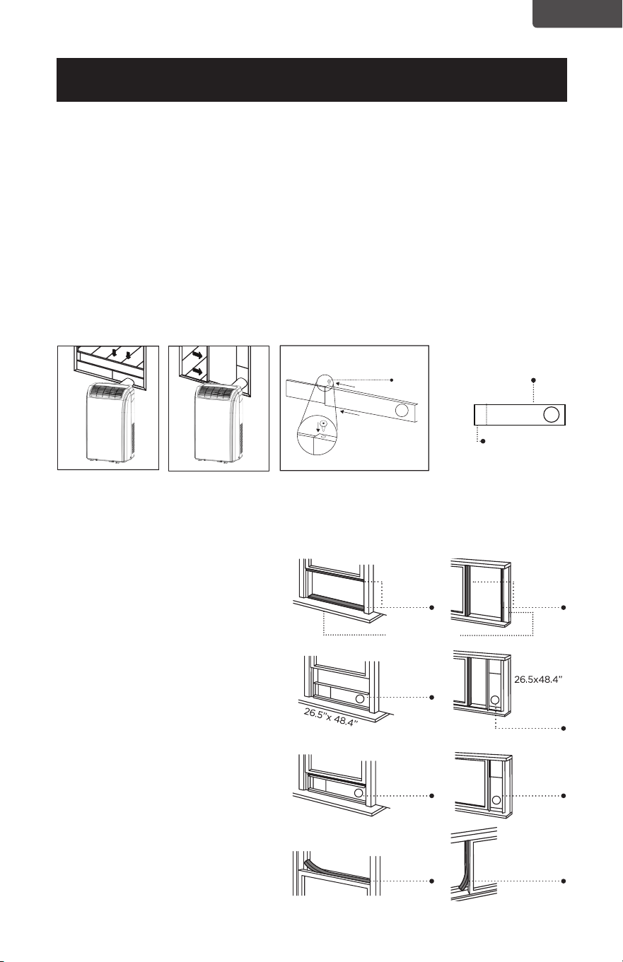
WINDOW SLIDER KIT INSTALLATION
Your window slider kit has been designed to t most standard “Vertical” and
“Horizontal” window applications; however, it may be necessary for you to
improvise/modify some aspect of the installation procedures for certain types of
windows. Minimum and maximum window openings:
MAXIMUM: 48.4” (123 cm) MINIMUM: 26.5” (67.5 cm)
NOTE: · A plastic locking pin is holding the window slider kit together during shipment. Prior
to installation, remove plastic locking pin, adjust to desired length and use provided
metal locking screws to secure.
NOTE: · If the window opening is less than 26.5”, the minimum length of the window slider
kit, cut the one with a hole in it short to t for the window opening. Never cut out
the hole in window slider kit.
SET UP & USE
DOUBLE-HUNG SASH/SLIDING CASEMENT WINDOW
INSTALLATION
1. Cut the foam seal (adhesive type) to the proper length and attach it to the
window sash.
Horizontal Window Vertical Window Window Slider Kit
Window slider kit can be secured by
inserting the locking screw
Cut on opposite
side of hole
2. Attach the window slider kit to the
window sash. Adjust the length of
the window slider kit according to
the width of window. Shorten the
adjustable window kit if the width
of window is less than 26.5”.
3. Cut the foam seal (adhesive type)
to the proper length and attach it
on the top of the window.
4. Close the window securely against
the window slider kit.
5. Secure the window slider kit to the
window sash.
6. Cut the foam seal to an appropriate
length and seal the open gap
between the top window frame and
outer window frame.
Page 12
EXHAUST HOSE INSTALLATION
The air exhaust hose and hose inlet must be installed or removed from the portable
air conditioner in accordance with the way it is being used:
COOL, DEHUMIDIFY and HEAT (Heat model BPACT12HWT and BPACT14HWT
only): Air exhaust hose and hose inlet should be connected to the portable
air conditioner.
FAN: Air exhaust hose and hose inlet should be disconnected from the portable air
conditioner.
To install:
1. The hose outlet and inlet are pre-assembled to the air exhaust hose.
2. Align the hose inlet with the slots over the air exhaust hose housing outlet to
assemble.
3. Insert the hose outlet into the window panel.
4. Afx the hose outlet into the window slider kit and seal.
NOTE: The exhaust hose can be compressed or extended
moderately, but it is desirable to keep the length to a
minimum. Also make sure that the hose does not
have any sharp bends.
SET UP & USE
Page 13
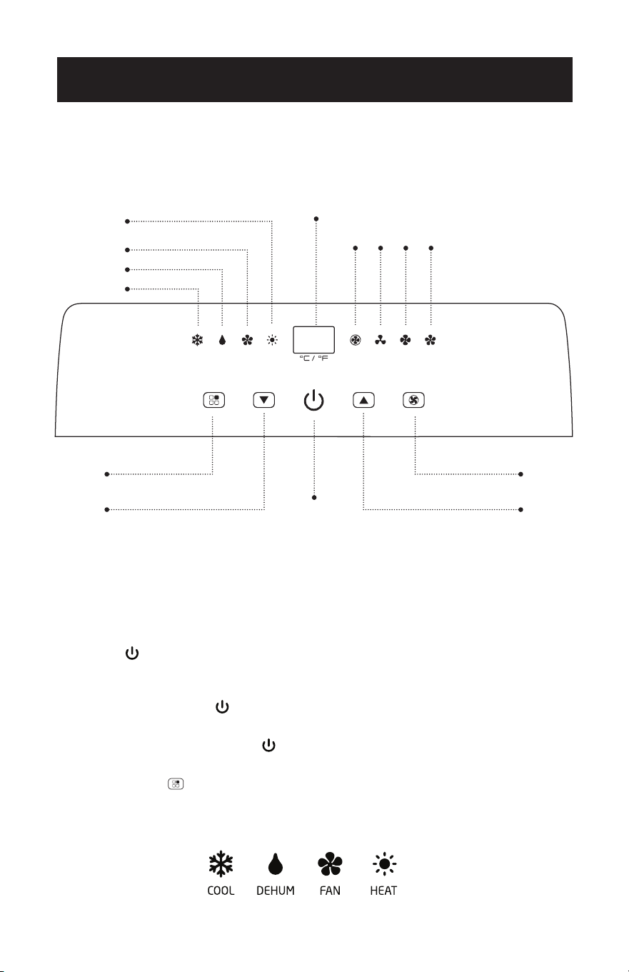
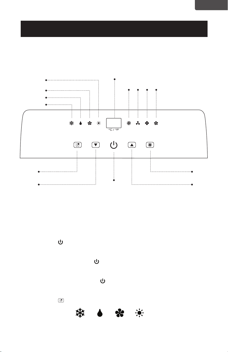
CONTROL PANEL
SET UP & USE
Cool
Fan
Display Area
AUTO
LOW
MED
HIGH
Dehumidify
Heat
(Heat models BPACT12HWT
and BPACT14HWT only)
Mode Selection
Button
Fan Speed
Selection Button
Increase Temp
Button
ON/OFF
Decrease Temp
Button
Pictures are for illustration purpose only. Your model may or may not have all the features.
OPERATING FROM THE CONTROL PANEL
The Control Panel enables you to manage all the main functions of the appliance, but
to fully utilize its potential, you must use the remote control unit.
TURNING THE APPLIANCE ON
• Press the button until the appliance turns on. The last function active when it was
turned o will appear.
• Never turn the air conditioner o by unplugging from the main power supply.
Always press the button , then wait for a few minutes before unplugging. This
allows the appliance to perform a cycle of checks to verify operation.
NOTE: Before pressing the Power button, make sure the condensate drain plug in
the rear of the unit is securely in place to avoid any leaking.
• Press the MODE button until the light corresponding to the required Mode lights
up.
*Heat models BPACT12HWT and BPACT14HWT only
Page 14
SET UP & USE
COOL MODE
Ideal for hot weather when you need to cool and dehumidify the room. To set
operation of the appliance correctly, press the Temp Up or Temp Down
buttons until the desired temperature is displayed.
Then select the fan speed by pressing the Fan Speed Button until the light
corresponding to the required fan speed lights up:
HIGH: The fan operates at maximum to reach the required temperatures as rapidly as
possible.
MED: Reduces Fan noise level but still maintains a good level of comfort.
LOW: For quiet operation.
AUTO: The appliance automatically selects the most suitable fan speed in relation to
the temperature set on the digital display.
DEHUMIDIFY MODE
Ideal for reducing humidity in spring and autumn, during rainy spells or in damp
rooms, etc.
Exhaust hose attachment is recommended for more eective dehumidification but
not required.
In dehumidify mode, the fan speed is automatically set to a low speed and cannot be
adjusted.
When an error code appears on the display screen on the control panel “E2”, the unit
will have to be drained.
FAN MODE
Press the mode key until the fan mode indicator lights up, indicating that the fan
function is selected.
Press the speed button to select the appropriate fan speed.
HEAT MODE (Heat models BPACT12HWT and BPACT14HWT only)
Press the MODE button until the HEAT mode indicator light appears. Select the
target temperature by pressing the or button until the corresponding value is
displayed. (Temperature range is 61
o
F-88
o
F (16
o
C-31
o
C)
Then select the fan speed by pressing the Fan Speed Button until the light
corresponding to the desired fan speed lights up: HIGH, MED, LOW, AUTO.
NOTE: At the beginning of this mode, you may have to wait a few seconds before the
appliance starts to give out hot air.
When an error code appears on the display screen “E4” in HEAT mode, the unit will
have to be drained.
NOTE: AUTO speed can only be selected using the control panel.
Page 15
SET UP & USE
OPERATING FROM THE REMOTE CONTROL
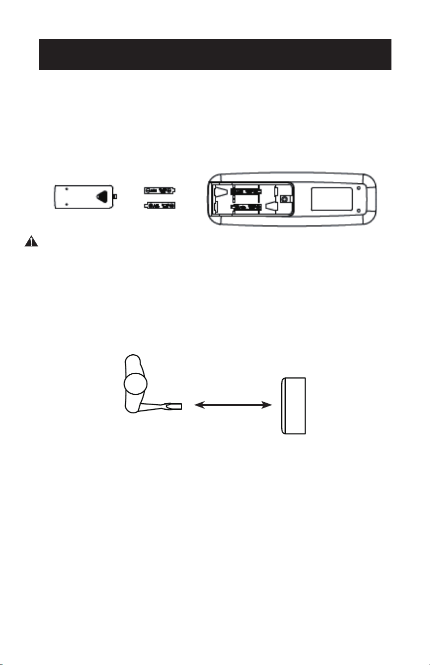
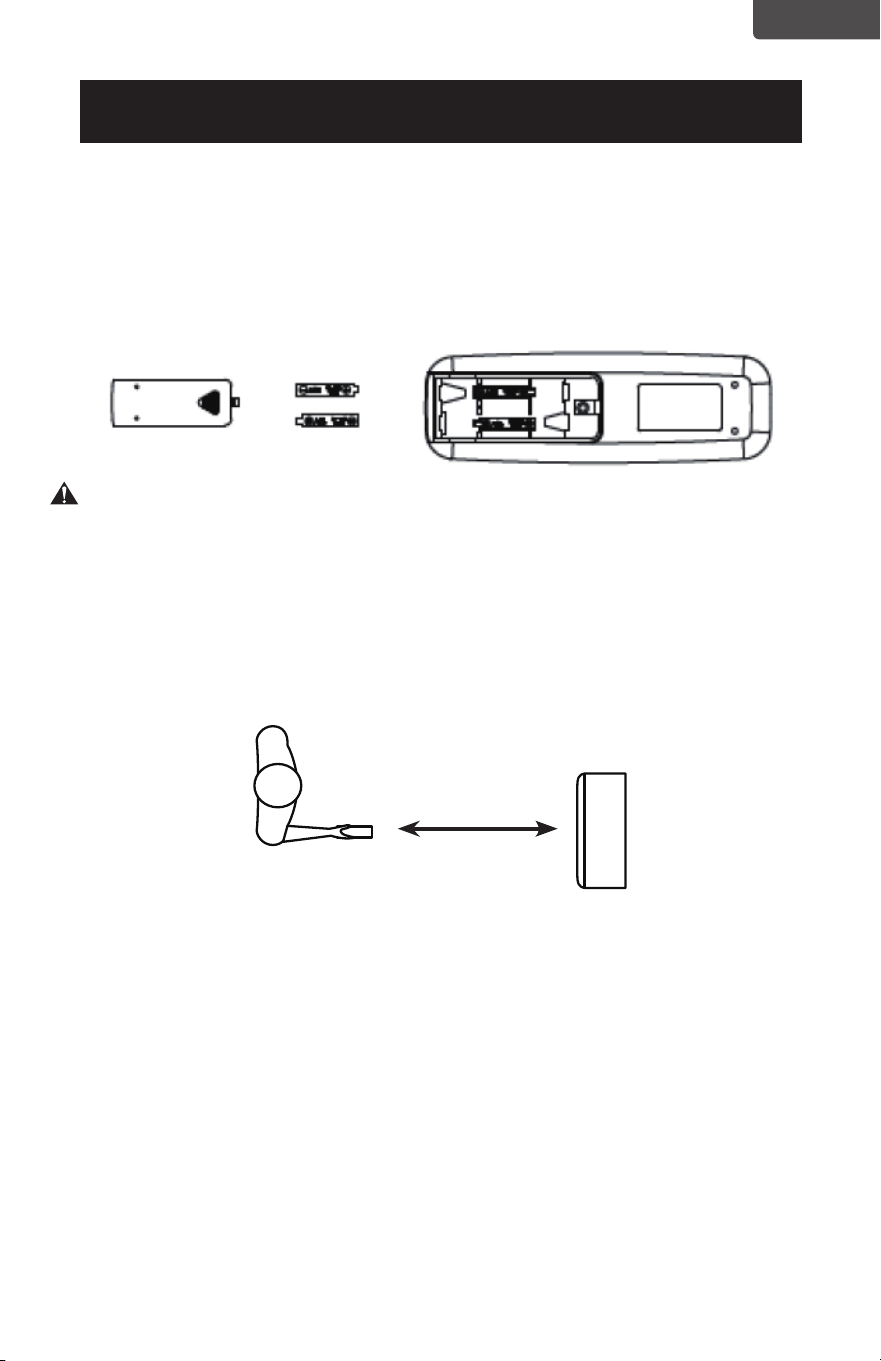
BATTERY INSTALLATION (BATTERIES NOT INCLUDED)
(1) Slide open the battery compartment cover.
(2) Insert 2 × “AAA” batteries as shown.
(3) Slide back the battery cover.
CAUTION: Use only AAA or IEC R03 1.5V alkaline batteries. Remove the batteries
if the remote is not used for a month or longer. Do not attempt to recharge the
batteries. Both batteries should be replaced at the same time. Do not dispose of
the batteries in a fire as they may explode.
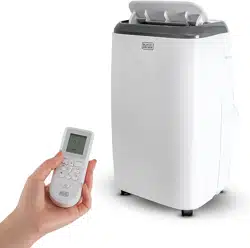
Point the remote control at the receiver on the appliance. The remote control must
be no more than 7 meters away from the appliance (without obstacle between the
remote control and the receiver).
The remote control must be handled with extreme care. Do not drop it or
expose it to direct sunlight or sources of heat.
23 Feet
Page 16
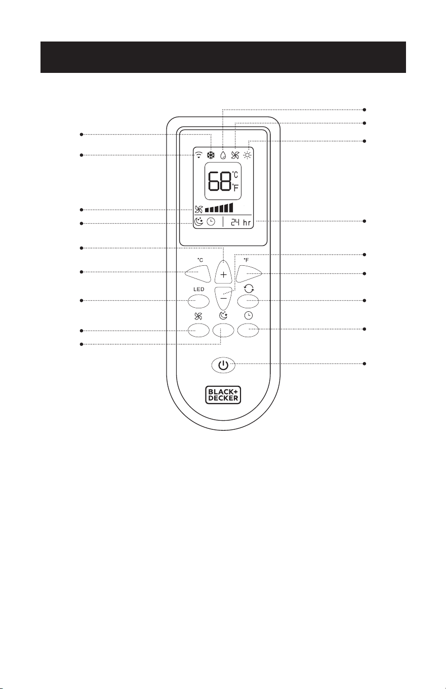
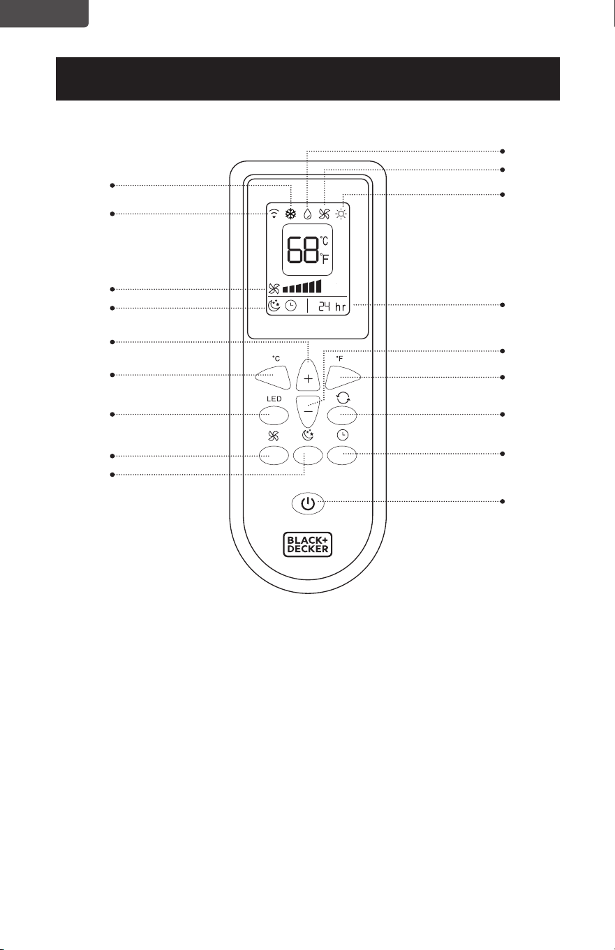
REMOTE CONTROL
SET UP & USE
POWER BUTTON: Press to Turn ON or OFF
TIMER BUTTON: Used to set a delay start or shut down time.
MODE BUTTON: Press the button to scroll through COOL, DEHUMIDIFY, FAN or
HEAT (HEAT mode for models BPACT12HWT and BPACT 14HWT
only)
o
C SELECTOR BUTTON: Celsius Display ON
o
F SELECTOR BUTTON: Fahrenheit Display ON
INCREASE: Increase the temperature/time setting.
DECREASE: Decrease the temperature/time setting.
LIGHT ON/OFF BUTTON: Illuminates the LED screen on the unit.
FAN SPEED BUTTON: Use to select the Low, Medium or High fan speed.
SLEEP BUTTON: Gradually adjusts the temperature.
Remote Signal
Cool
Dehumidify
Fan
Timer Selection
o
F Selector Button
Increase Button
o
C Selector Button
Light On/O Button
Fan Speed Button
Sleep Button
Fan Speed
Sleep
Decrease Button
Mode Button
Timer Button
Power Button
Heat
(Heat models BPACT12HWT and
BPACT14HWT only)
Page 17
SET UP & USE
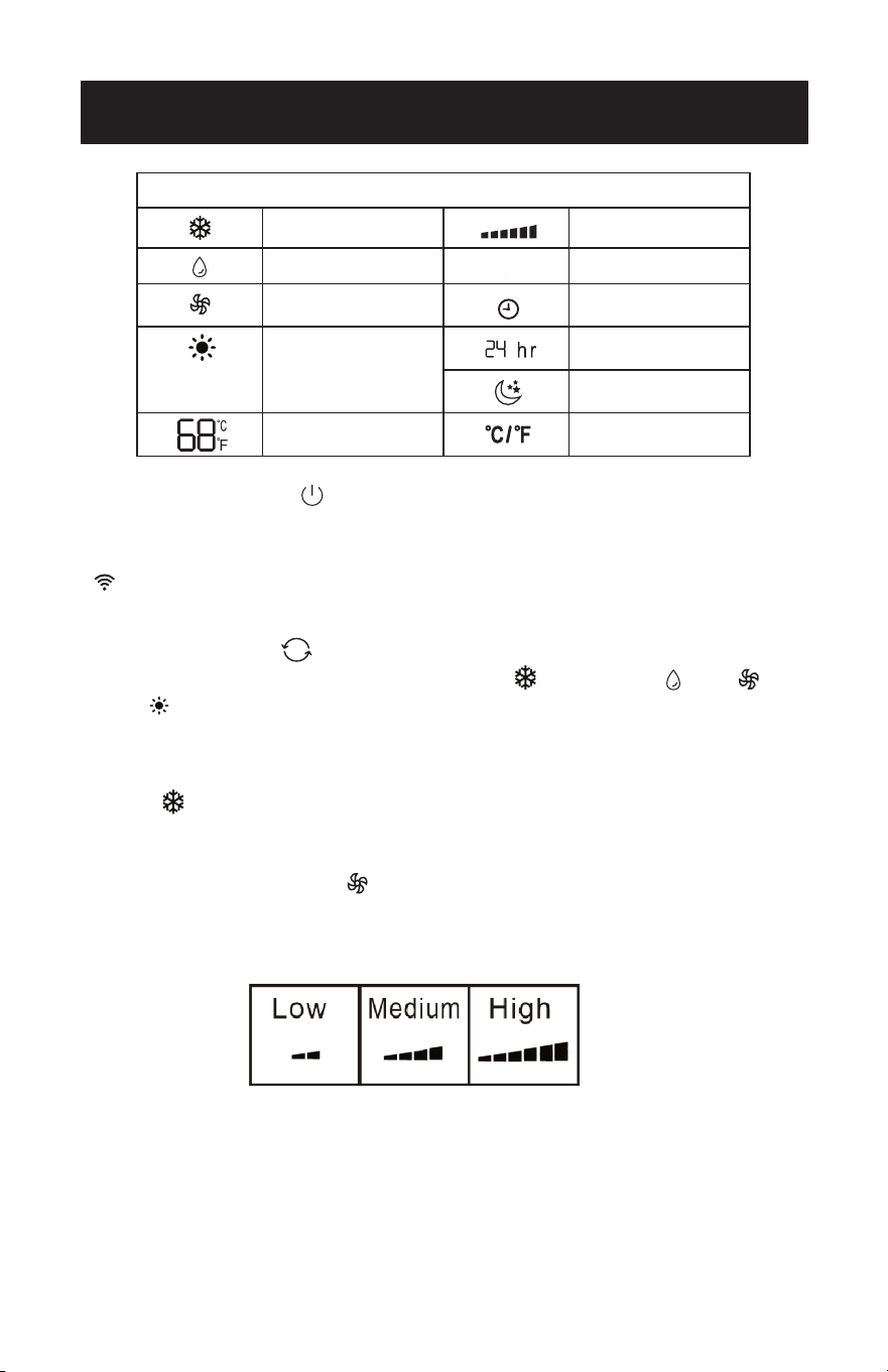
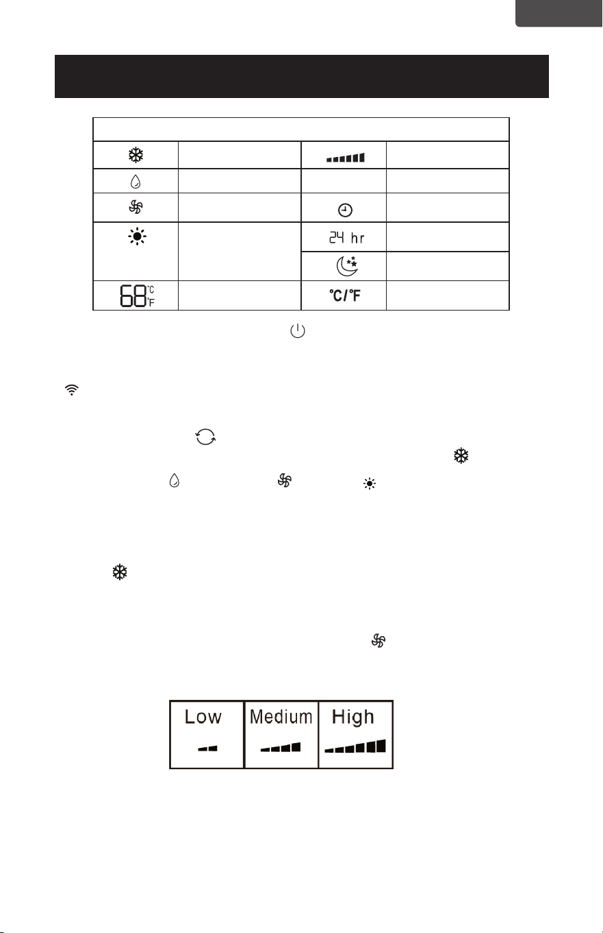
LED Display Indicators
Fan speed
Dehumidify mode Swing
Fan mode Timer on
Heat mode
Heat models
BPP08HWTB and
BPP10HWTB only
Sleep
Display temp. or
hours
Fahrenheit or
Celsius.
Timer o
POWER BUTTON
• Press to Turn Air Conditioner ON or OFF. Press LED button to illuminate the
LED screen on the unit.
•
Will show on the remote LED screen when buttons are pressed to show that
the remote control is sending a signal to the air conditioner.
MODE BUTTON
• Press the mode button to scroll through COOL , DEHUMIDIFY , FAN ,
HEAT (Heat models BPACT12HWT and BPACT14HWT only).
• The corresponding symbol will illuminate on the LED display to indicate which
mode is selected.
COOL
• Select the target temperature 61˚F–88˚F (16˚C – 31˚C) by pressing the + or -
buttons until the desired temperature is displayed on the LED screen.
• Press the Fan Speed Button to select Low, Medium, or High Speed.
BPACT12HWT and
BPACT14HWT only
Cool mode
Page 18
SET UP & USE
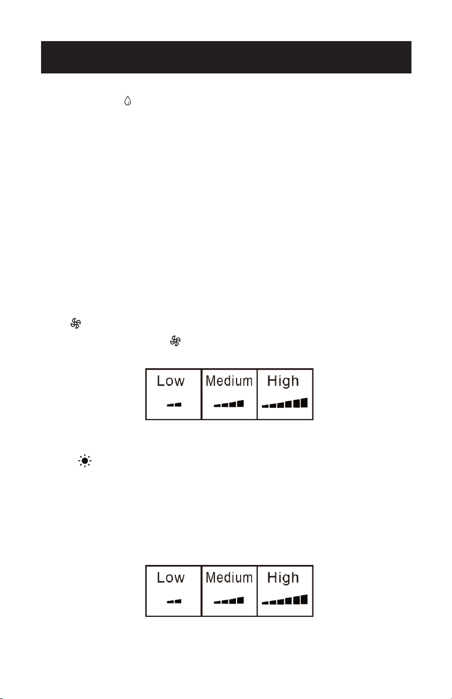
DEHUMIDIFY
• Ideal for reducing humidity.
• Keep window and door closed for the best dehumidifying eect.
• Exhaust hose attachment is not required in this mode but it is recommended for
more eective dehumidification.
• It is recommended that the dehumidification drain and drain hose be used for
continuous drainage.
• FULL TANK - When an error code appears on the display screen on the control
panel “E2” in COOL or DEHUMIDIFY mode, or “E4” in HEAT mode, the unit will have
to be drained.
NOTE: Refer to Water Drainage section.
• In this mode, fan speed is selected automatically by the appliance and can not be
set manually.
FAN
• Press the Fan Speed Button to select Low, Medium or High Speed.
HEAT (Heat models BPACT12HWT and BPACT14HWT only)
• Select the target temperature 61˚F–88˚F (16˚C–31˚C) by pressing the + or - buttons
until the desired temperature is displayed on the LED screen.
• Press the speed button to select Low, Medium or High fan speed.
NOTE: At the beginning of this mode, you may have to wait a few seconds before the
appliance starts to give out hot air.
Page 19
SET UP & USE
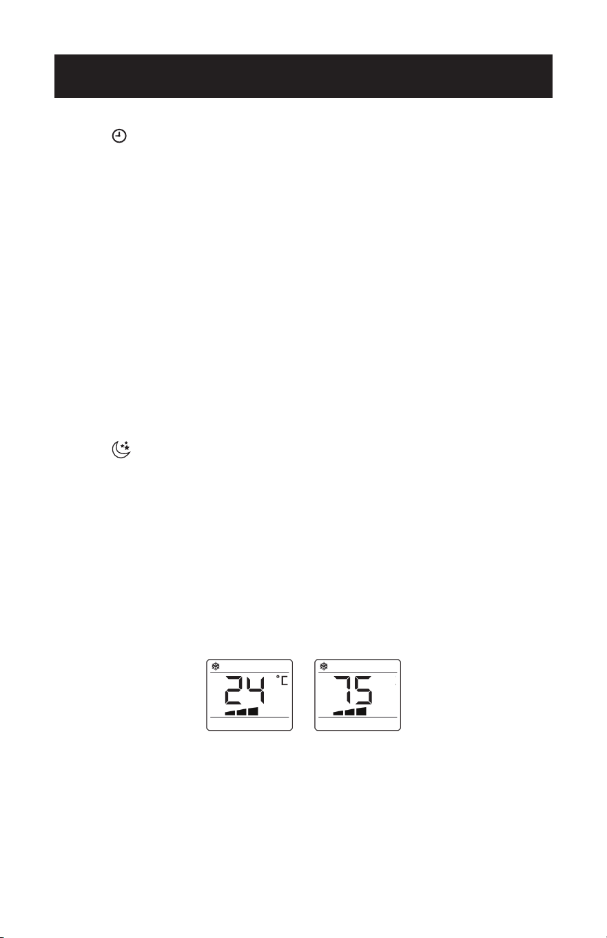
TIMER
• To set the AUTO STOP timer. When the unit is ON, press the TIMER button. The
TIME ON/OFF symbol on the remote LCD display will blink.
• Press the + or - button to select the AUTO TIME by 1 hour increments, up to 24
hours. The Remote LCD Display will indicate the selected time. Press the TIMER
button again to set the selected time. There will be a steady TIME ON/OFF symbol
on the remote LCD display and the TIMER indicator light will be illuminated on the
control panel of the unit to show that the AUTO STOP program is initiated.
• To set the AUTO START timer. When the unit is OFF, press the TIMER button. The
TIME ON/OFF symbol on the remote LCD display will blink.
• Press the + or - button to select the AUTO TIME by 1 hour increments, up to 24
hours. The Remote LCD Display will indicate the selected time. Press the TIMER
button again to set the selected time. There will be a steady TIME ON/OFF symbol
on the remote LCD display and the TIMER indicator light will be illuminated on the
control panel of the unit to show that the AUTO START program is initiated.
• Pressing the POWER button or the TIMER button will cancel the AUTO START/STOP
timed program and the timer indicator light will not be illuminated.
SLEEP
• The SLEEP function gradually adjusts the temperature of the rooms to provide a
comfortable environment. Press the SLEEP button to activate.
• In COOL mode, the temperature will increase 2°F after an hour and 4°F after 2
hours.
• In HEAT mode, the temperature will decrease 2°F after an hour and 4°F after 2
hours.
• To cancel this setting press the SLEEP button again.
°C / °F SELECTOR BUTTONS
• When the appliance is powered on, press the °F selector button to display the
temperature in Fahrenheit.
• Press the °C selector button to display the temperature in Celsius.
°
F
Page 20
SET UP & USE
WATER DRAINAGE FOR COOL AND HEAT MODES
This air conditioner is equipped with auto water evaporation so the water compartment
would not typically fill in cooling or heating mode unless there is high humidity. Water
drainage will generally only be required at the end of the season for these modes. (see
START-END OF SEASON OPERATIONS).
NOTE: When an error code appears on the display screen on the control panel “E2” in
COOL or DEHUMIDIFY mode, or “E4” in HEAT mode, the unit will have to be
drained.
Intermittent Draining
• Unplug the unit from the power source. Carefully move the unit to a drain area
over your basement floor or drip pan (not included). Remove the bottom drain
cap.
• Let the water drain away and replace the drain cap. Restart the machine until the
error codes E2 or E4 disappears. If the error repeats, call for service.
NOTE: Be sure to reinstall the bottom drain plug before using the unit.
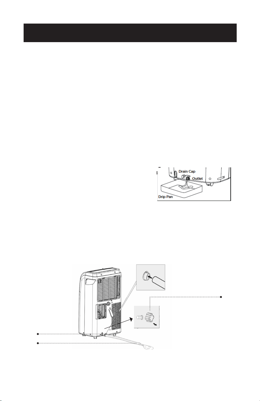
Continuous Draining
• Unplug the unit from the power source. Remove the bottom drain cap. While
doing this operation, some residual water may spill. Have a drip pan (not
supplied) to collect the water.
• Connect the drain hose (supplied) as shown in the diagram. The water can be
continuously drained through the hose into a floor drain or drip tray.
• Turn on the unit.
Drain outlet
Drain cap
Drain hose
WAIT 3 MINUTES BEFORE RESUMING OPERATION
• After the unit has stopped, it cannot be restarted for 3 minutes. Operation will
automatically restart after 3 minutes.
Page 21
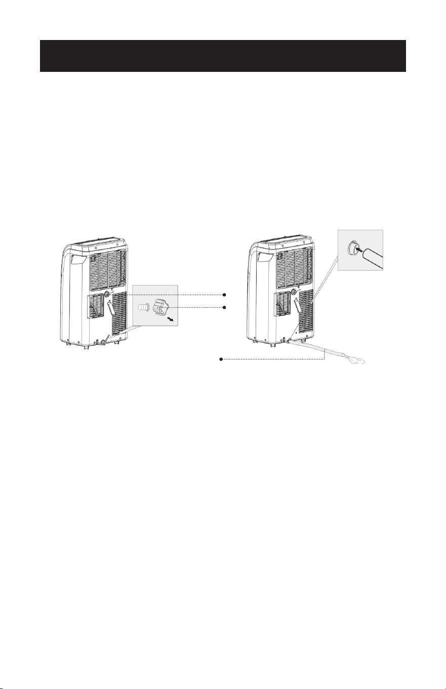
Continuous Draining for Dehumidification Mode
• Unplug the unit from the power source.
• Remove the drain cap located in the back center of the unit. While doing this
operation, some residual water may spill. Have a drip pan (not supplied) to col-
lect the water.
• Connect the drain hose (supplied) as shown in the diagram. The water can be
continuously drained through the hose into a floor drain or bucket.
Turn on the unit.
SET UP & USE
WAIT 3 MINUTES BEFORE RESUMING OPERATION
• After the unit has stopped, it cannot be restarted for 3 minutes. Operation will
automatically restart after 3 minutes.
Drain outlet
Drain cap
Drain hose
Page 22
CLEANING & CARE
CLEANING
WARNING: Before cleaning or maintenance, turn the appliance o by pressing
the button on the control panel or button on the remote control.
Unplug from the electrical outlet.
CLEANING THE CABINET
You should clean the appliance with a slightly damp cloth then dry with a dry
cloth.
• Never saturate the air conditioner with water.
• Never use petrol, alcohol or solvents to clean the appliance.
• Never spray insecticide liquids or similar near the air conditioner.
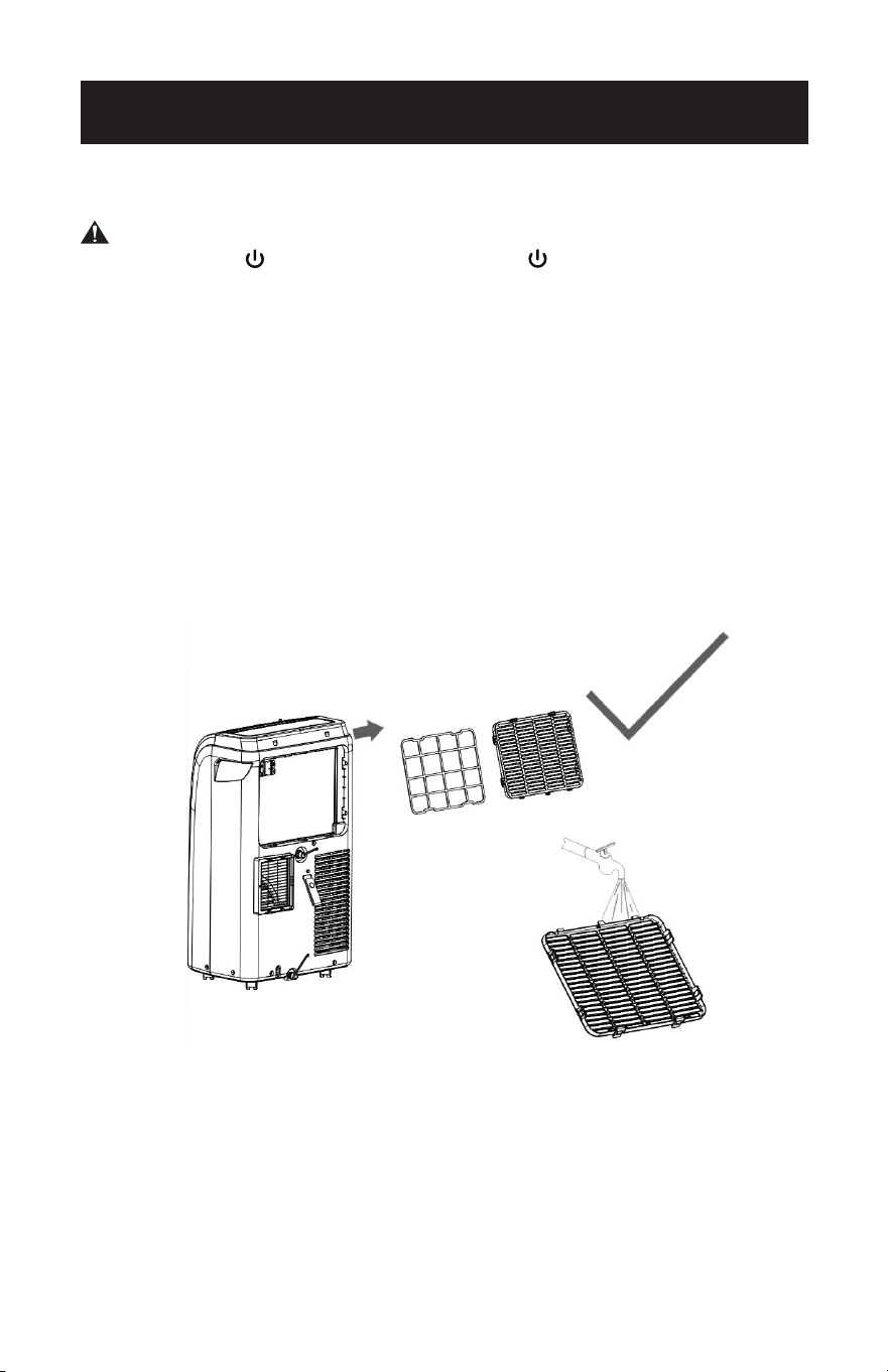
CLEANING THE FILTER
To keep your air conditioner working eciently, you should clean the evaporator
filter every week of operation.
The filter is housed in the intake grill.
Use a vacuum cleaner to remove dust accumulations from the filter.
If it is very dirty, immerse in warm water and rinse a number of times.
The water should be luke warm.
After washing, leave the lter to dry then re-insert the lter.
START - END OF SEASON OPERATIONS
START OF SEASON CHECKS
Make sure the power cable and plug are undamaged.
Follow the installation instructions precisely.
END OF SEASON OPERATIONS
See Water Drainage section to make sure the air conditioner is completely
drained of water.
Clean the filter and dry thoroughly before reinstalling
Page 23
TROUBLESHOOTING & WARRANTY
BEFORE YOU CALL FOR SERVICE
IF THE AIR CONDITIONER FAILS TO OPERATE:
A) Check to make sure that the air conditioner is plugged in securely. If it is
not, remove the plug from the outlet, wait 10 seconds and plug it in again
securely.
B) Check for a blown circuit fuse or a tripped main circuit breaker. If these seem
to be operating properly, test the outlet with another appliance.
WARNING
IF NONE OF THE ABOVE SOLVES THE PROBLEM, CONTACT A QUALIFIED
TECHNICIAN. DO NOT TRY TO ADJUST OR REPAIR THE AIR CONDITIONER
YOURSELF. Any person who is involved with working on or breaking into a
refrigerant circuit should hold a current valid certicate from an industry-
accredited assessment authority, which authorizes their competence to handle
refrigerants safely in accordance with an industry recognized assessment
specication.
WARNING
Do not use means to accelerate the defrosting process or to clean other than
those recommended by the manufacturer.
The appliance shall be stored in a room without continuously operating ignition
sources (for example: open ames, an operating gas appliance or an operating
electric heater).
Do not pierce or burn.
Be aware that refrigerants may not contain an odour.
WARNING
Servicing shall only be performed as recommended by the equipment
manufacturer. Maintenance and repair requiring the assistance of other skilled
personnel shall be carried out under the supervision of the person competent in
the use of the ammable refrigerants.
CUSTOMER SERVICE
IMPORTANT
DO NOT RETURN THIS PRODUCT TO THE STORE
If you have a problem with this product, please contact the
W Appliance Co. Customer Satisfaction Center at
844-299-0879.
DATED PROOF OF PURCHASE, MODEL # AND SERIAL #
REQUIRED FOR WARRANTY SERVICE
Page 24
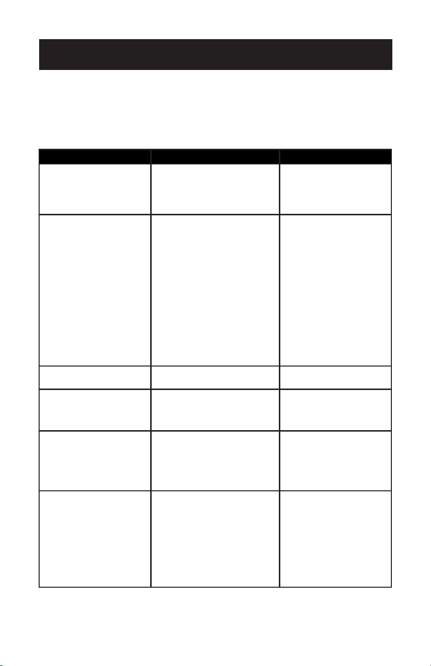
TROUBLESHOOTING & WARRANTY
Troubleshoot your problem by using the chart below. If the air conditioner still does
not work properly, contact BLACK+DECKER customer service center or the nearest
authorized service center. Customers must never troubleshoot internal components.
TROUBLE POSSIBLE CAUSE POSSIBLE REMEDY
Unit does not start when
pressing ON/OFF button
A. The water tank may be full
if LED display indicates “E2”
in COOL or DEHUMIDIFY
mode, or “E4” in HEAT
mode.
A. Drain the water
B. Reset the temperature
Not cool enough A. The windows or doors in the
room are not closed
B. There are heat sources
inside the room
C. Exhaust air duct is not
connected or blocked
D. Temperature setting is too
high
E. Air lter is blocked by dust
F. The unit will take approx 3
minutes of operation before
cooling/heating occurs.
A. Make sure all the
windows and doors are
closed
B. Remove the heat
sources if possible
C. Connect the duct
and make sure it can
function properly
D. Decrease the set
temperature
E. Clean the air lter
F. A mircoprocessor
control delays the
compressor from
operating until 3 mins
have passed.
Noisy or vibration A. The surface is not level or
not at enough
A. Place the unit on a at,
level surface if possible
Unit does not run and
indicates “E2” in COOL
or DEHUMIDIFY mode, or
“E4” in HEAT mode.
A. The unit needs to be
drained.
A. Refer to water drainage
section.
LED display “E0” , “E1”,
“E3”
A. EO - Room temperature
sensor issue
B. E1- Condenser temperature
sensor
C. E3- Evaporator temperature
sensor
A. Contact the Customer
Satisfaction Center for
assistance with error
code.
Remote is not working A. Nothing Appears on the LED
screen.
B. The temperature and
symbols appear on the LED
screen but the selection
cannot be changed.
A. Press the LED button
on the remote. If it does
not illuminate, change
batteries.
B. Make sure the remote
is being pointed at the
remote control receiver
on the unit within 23
feet away and that there
are no obstructions.

Page 25
TROUBLESHOOTING & WARRANTY
LIMITED WARRANTY
Any repair, replacement, or warranty service,
and all questions about this product should be
directed to W Appliance Co. at 844-299-0879
from the USA or Puerto Rico.
W Appliance Co. warrants to the original purchaser
that the product will be free from defects in material,
parts and workmanship for the period designated for
this product. The warranty commences the day the
product is purchased and covers up to a period of
1 year (12 months) for labor/1 year (12 months) for
parts (manufacturing defects only)/and a total of 5
years (60 months) for compressor part only.
W Appliance Co. agrees that it will, at its option,
replace the defective product with either a new
or remanufactured unit equivalent to your original
purchase during the warranty period.
Exclusions: This warranty does not apply to the
below:
1. If the appearance or exterior of
the product has been damaged or
defaced, altered or modied in design or
construction.
2. If the product original serial number
has been altered or removed or cannot
be readily determined.
3. If there is damaged due to power line
surge, user damage to the AC power
cord or connection to improper voltage
source.
4. If damage is due to general misuse,
accidents or acts of God.
5. If repair attempts are done by
unauthorized service agents, use of
parts other than genuine parts or parts
obtained from persons other than
authorized service companies.
6. On units that have been transferred
from the original owner.
7. On products that have been purchased
as refurbished, like new, second-hand, in
a “As-Is” or “Final Sale” terms.
8. To products used in a commercial or
rental setting.
9. To products used in settings other than
ordinary household use or used other
than in accordance with the provided
instructions.
10. To damages for service calls for
improper installations.
11. Transportation and shipping costs
associated with the replacement of
the unit.
12. Service calls to instruct you how to use
your product.
13. Service calls to repair or replace the
house fuse, reset the circuit breaker or
correct the wiring in the house.
REPAIR OR REPLACEMENT AS PROVIDED UNDER
THIS WARRANTY IS THE EXCLUSIVE REMEDY OF
THE CUSTOMER; W Appliance Co. SHALL NOT BE
LIABLE FOR ANY INCIDENTAL OR CONSEQUENTIAL
DAMAGES FOR BREACH OF ANY EXPRESS OR
IMPLIED WARRANTY ON THIS PRODUCT, EXCEPT
TO THE EXTENT PROHIBITED BY APPLICABLE LAW.
ANY IMPLIED WARRANTY OF MERCHANTABILITY
OF FITNESS FOR A PARTICULAR PURPOSE ON THIS
PRODUCT IS LIMITED TO THE DURATION OF THE
WARRANTY.
Some states do not allow the exclusion or limitations
of incidental or consequential damages, or limitations
on how long the warranty lasts. In these cases the
above exclusions or limitations may not apply to you.
This warranty gives you specic legal rights and you
may also have other rights which vary from state to
state.
Obtaining Service: To obtain service, product
literature, supplies or accessories please call
844-299-0879 to create a ticket for exchange/repair.
Please make sure to provide the date of purchase,
model number and a brief description of the problem.
Our customer service representative
will contact you or send detailed return instructions.
W Appliance Co. does not warrant that the appliance will work
properly in all environmental conditions, and makes no warranty
and representation, either implied or expressed, with respect
to the quality, performance, merchantability, or tness for a
particular purpose other than the purpose identied within this
user’s manual. W Appliance Co. has made every effort to ensure
that this user’s manual is accurate and disclaims liability for any
inaccuracies or omissions that may have occurred. Information
in this user’s manual is subject to change without notice and
does not represent a commitment on the part of W Appliance
Co.. W Appliance Co. reserves the right to make improvements
to this user’s manual and/or to the products described in this
user’s manual at any time without notice. If you nd information
in this manual that is incorrect, misleading, or incomplete, please
contact us at 844-299-0879.
W Appliance Co.
1356 Broadway
New York, NY 10018

This device complies with part 15 of the FCC rules. Operation is subject to the
following two conditions: 1) This device may not cause harmful interference, and
2) This device must accept any interference received, including interference that
may cause undesired operation. This equipment has been tested and found to
comply with the limits for a Class B digital device, pursuant to Part 15 of the FCC
rules. These limits are designed to provide reasonable protection against harm-
ful interference in a residential installation. This equipment generates, uses and
can radiate radio frequency energy and, if not installed and used in accordance
with the instructions, may cause harmful interference to radio communications.
However, there is no guarantee that the interference will not occur in a particular
installation. If this equipment does cause harmful interference to radio or televi-
sion reception, which can be determined by turning the equipment o and on,
the user is encouraged to try to correct the interference by one or more of the
following measures: a) Reorient or relocate the receiving antenna. b) Increase the
separation between the equipment and the receiver. c) Connect the equipment
into an outlet dierent from that which the receiver is connected. d) Consult the
dealer or an experienced radio/TV technician for help.
BLACK & DECKER, BLACK+DECKER, the BLACK & DECKER and
BLACK+DECKER logos and product names and the orange and black color
scheme are trademarks of The Black & Decker Corporation, used under license.
All rights reserved.
Product in this box may differ slightly from that pictured. Does not affect
function. Not all accessories shown in photography are included in this
package.
Imported by W Appliance, Inc, 1356 Broadway, New York, NY 10018
March 2022 Printed in China
Page 27
FRANÇAIS
MANUEL D’INSTRUCTIONS
CLIMATISEUR PORTABLE
Merci d’avoir choisi BLACK+DECKER!
VEUILLEZ LIRE ATTENTIVEMENT AVANT DE RETOURNER
CE PRODUIT POUR UNE RAISON QUELCONQUE.
Si vous avez une question ou rencontrez un problème avec votre achat
BLACK+DECKER, allez sur www.blackanddecker.com/instantanswers Si
vous ne trouvez pas la réponse ou n’avez pas accès à Internet, appelez au
844-299-0879 de 10 h30 à 18 h30 HNE du lundi au vendredi pour parler à un
agent. Veuillez avoir le numéro de catalogue disponible quand vous appelez.
GARDEZ CE MANUEL POUR RÉFÉRENCE ULTÉRIEURE.
NUMÉRO DE CATALOGUE
BPACT08WT
BPACT10WT
BPACT12WT
BPACT12HWT
BPACT14WT
BPACT14HWT

Page 28
FRANÇAIS
Page 28
Merci d’avoir acheté notre produit
BLACK+DECKER. Ce manuel facile
à utiliser vous guidera pour obtenir
la meilleure utilisation de votre
climatiseur.
N’oubliez pas d’enregistrer les
numéros de modèle et de série. Ils
sont sur une étiquette à l’arrière.
Agrafer votre reçu à votre manuel.
Vous en aurez besoin pour obtenir le service
de garantie.
Numéro de modèle
Numéro de série
Date d’achat
ENREGISTREMENT DES PRODUITS
TABLE DES MATIÈRES
INFORMATIONS DE SÉCURITÉ
Consignes De Sécurité Importantes .....................................................................................................................29-30
Instructions De Mise À La Terre ........................................................................................................................................31
Cordon d’Alimentation Et Fiche DICF .............................................................................................................. 32
Directives De Sécurité ......................................................................................................................................... 33
Conditions De Fonctionnement ..................................................................................................................... 34
CONFIGURATION ET UTILISATION
Pièces Et Caractéristiques ...................................................................................................................................................35
Guide d’Installation .................................................................................................................................................36
Installation Du Kit De Glissière De Fenêtre ................................................................................................. 37
Installation Du Tuyau d’Échappement ..........................................................................................................38
Panneau De Commande ...................................................................................................................................39
Fonctionnement à partir du Panneau De Commande .................................................................... 39-40
Fonctionnement à partir de la Télécommande ..........................................................................................41
Télécommande ...............................................................................................................................................42-45
Drainage De l’Eau...........................................................................................................................................46-47
NETTOYAGE ET ENTRETIEN ..............................................................................................................48
DÉPANNAGE ET GARANTIE
Avant d’Appeler Pour Le Service ..................................................................................................................... 49
Service Client ......................................................................................................................................................... 49
Dépannage ............................................................................................................................................................. 50
Garantie Limitée ......................................................................................................................................................................51
Page 29
FRANÇAIS
Page 29
INFORMATIONS DE SÉCURITÉ
CONSIGNES DE SÉCURITÉ IMPORTANTES
1. Pour réduire le risque de blessure, lisez ce guide avant d’utiliser l’appareil.
2. Le climatiseur doit être connecté à la prise électrique appropriée avec la prise électrique
appropriée avec l’alimentation électrique appropriée.
3. Une mise à la terre appropriée doit être assurée pour réduire le risque de choc et d’incendie.
NE PAS COUPER OU RETIRER LA BROCHE DE MISE À LA TERRE. Si vous n’avez pas de
prise électrique à trois broches dans le mur, demandez à un électricien certié d’installer la
prise appropriée. La prise murale DOIT être correctement mise à la terre.
4. N’utilisez pas le climatiseur si le cordon d’alimentation est efloché ou endommagé. Évitez de
l’utiliser s’il y a des ssures ou des dommages par abrasion le long de la longueur, la che ou
si l’appareil fonctionne mal ou est endommagé en aucune manière. Contactez un technicien
de maintenance agréé pour un examen, des réparations ou des ajustements.
5. N’UTILISEZ PAS UN ADAPTATEUR OU UNE RALLONGE.
6. Ne bloquez pas le ux d’air autour du climatiseur. Le tuyau d’échappement doit être exempt
de toute obstruction.
7. Débranchez toujours le climatiseur avant d’entretenir ou de déplacer l’appareil.
8. Ne pas installer ou utiliser le climatiseur dans une zone où l’atmosphère contient des gaz
combustibles ou où l’atmosphère est huileuse ou sulfureuse. Évitez tout produit chimique
entrant en contact avec votre climatiseur.
9. Ne placez aucun objet sur le dessus de l’appareil.
10. N’utilisez jamais le climatiseur sans ltres en place.
11. N’utilisez pas le climatiseur près d’une baignoire, d’une douche ou d’un lavabo.
12. Cet appareil n’est pas destiné à être utilisé par des personnes (y compris des enfants)
ayant des capacités sensorielles ou mentales réduites ou un manque d’expérience et de
connaissances, à moins qu’elles n’aient reçu une supervision ou des instructions concernant
l’utilisation de l’appareil par une personne responsable de leur sécurité.
13. Les enfants doivent être surveillés pour s’assurer qu’ils ne jouent pas avec l’appareil.
14. Si le CORDON D’ALIMENTATION est endommagé, il doit être remplacé par le fabricant, un
agent de service ou des personnes qualiées an d’éviter un danger.
15. Le climatiseur doit être installé conformément aux réglementations nationales en matière de
câblage.
AVERTISSEMENT
AVERTISSEMENT - Dangers
ou pratiques dangereuses qui
POURRAIENT entraîner des
blessures graves ou mortelles
DANGER
DANGER - Dangers immédiats
qui VONT entraîner des blessures
graves ou mortelles
ATTENTION
ATTENTION - Dangers ou pratiques
dangereuses qui POURRAIENT
entraîner des blessures corporelles
mineures
AVERTISSEMENT
Lors de l’utilisation d’appareils électriques, des mesures de sécurité de
base doivent être suivies, y compris les suivantes

Page 30
FRANÇAIS
MANIPULATION DE PILES ALCALINES
1. Si le liquide de la pile entre accidentellement dans vos yeux, il y a une menace de
perte de la vue, ne les frottez pas. Rincez immédiatement vos yeux avec de l’eau du
robinet propre, puis consultez immédiatement un médecin.
2. Ne mettez pas la pile dans un feu, ne l’exposez pas à la chaleur, ne la démontez pas
et ne la modiez pas. Si l’isolation ou la soupape de sécurité est endommagée, la
pile peut fuir, surchauffer ou exploser.
3. N’insérez pas la pile avec les pôles inversés. Cela peut provoquer une anomalie ou
un court-circuit et la pile peut fuir, surchauffer ou exploser.
4. Gardez la pile hors de la portée des enfants. Si la pile est avalée, contactez
immédiatement un médecin.
5. Si le liquide alcalin pénètre dans votre bouche, rincez-la à l’eau et contactez
immédiatement un médecin.
6. Si le liquide alcalin pénètre sur votre peau ou vos vêtements, il peut brûler votre
peau, rincez soigneusement la zone affectée avec de l’eau du robinet.
7. Ne mélangez pas les piles neuves et anciennes ou d’autres marques de piles. Les
différents attributs peuvent entraîner une fuite de liquide, surchauffe ou explosion
de la pile.
8. Cette pile n’a pas été conçue pour être rechargée. La recharge de cette pile peut
endommager l’isolation ou la structure interne et peut provoquer une fuite de
liquide, surchauffe ou explosion de la pile.
9. N’endommagez pas et ne enlevez pas l’étiquette à l’extérieur de la pile. Cela peut
provoquer un court-circuit de la pile, une fuite de liquide, une surchauffe ou une
explosion.
10. N’échappez pas, ne jetez pas et n’exposez pas la pile à des impacts extrêmes. Cela
peut provoquer une fuite de liquide, une surchauffe ou une explosion de la pile.
11. Ne modiez pas la forme de la pile. Si l’isolation ou la soupape de sécurité est
endommagée, la pile peut fuir, surchauffer ou exploser.
12. Enlevez immédiatement les piles lorsqu’elles ont perdu toute puissance. Laisser les
piles dans l’unité pendant une longue période peut provoquer des fuites de uide,
une surchauffe ou une explosion à cause du gaz généré par les piles.
13. Enlevez les piles de l’appareil quand vous ne l’utilisez pas pendant une période
prolongée. Les piles peuvent fuir, surchauffer ou exploser à cause du gaz généré
par les piles.
14. N’appliquez pas de soudure directement sur les piles. La chaleur peut provoquer
des fuites de liquide, une surchauffe ou une explosion des piles.
15. Ne mouillez pas les piles. Cela peut provoquer une surchauffe des piles.
16. Rangez les piles dans un endroit à l’abri de la lumière directe du soleil où la
température et l’humidité ne sont pas élevées. Si vous ne le faites pas, les piles
risquent de fuir, de surchauffer ou d’exploser. En outre, cela peut entraîner une
baisse de la durée de vie et des performances des piles.
17. Suivez les réglementations du gouvernement local lors de la mise au rebut de ces
piles.
18. NE MÉLANGEZ JAMAIS de piles alcalines, standard (carbone-zinc), rechargeables
(nickel-cadmium) avec ce produit.
GARDEZ CES INSTRUCTIONS
USAGE DOMESTIQUE UNIQUEMENT
AVERTISSEMENT
Lors de la manipulation de piles alcalines, des précautions de sécurité
de base devraient être suivies, y compris les suivantes
INFORMATIONS DE SÉCURITÉ

Page 31
FRANÇAIS
INSTRUCTIONS DE MISE À LA TERRE
EXIGENCES ÉLECTRIQUES
En cas de mauvais fonctionnement ou de panne, la mise à la terre fournit un
chemin de moindre résistance pour le courant électrique an de réduire le
risque de choc électrique. L’appareil doit être connecté à un cordon ayant un
conducteur de mise à la terre de l’équipement et une che de mise à la terre. La
che doit être branchée sur une prise appropriée qui est correctement installée
et mise à la terre conformément à tous les codes et ordonnances locaux.
DANGER - Une mauvaise connexion du conducteur de mise à la terre de
l’équipement peut entraîner un risque de choc électrique. Le conducteur
à isolation dont la surface extérieure est verte avec ou sans bandes jaunes
est le conducteur de mise à la terre de l’équipement. Si la réparation ou le
remplacement du cordon ou de la fiche est nécessaire, ne connectez pas le
conducteur de mise à la terre de l’équipement à une borne sous tension. Vérifiez
auprès d’un électricien ou d’un technicien qualifié si les instructions de mise à la
terre ne sont pas complètement comprises ou si l’appareil est correctement mis
à la terre. Ne modifiez pas la fiche connectée à l’appareil – s’il ne s’adapte pas à la
prise, faites installer une prise appropriée par un électricien qualifié.
POUR UN APPAREIL MISE À LA TERRE, CONNECTÉ PAR CORDON D’UNE
PUISSANCE INFÉRIEURE À 15A ET DESTINÉ À ÊTRE UTILISÉ SUR UN CIRCUIT
D’ALIMENTATION NOMINAL DE 120V
L’appareil est destiné à être utilisé sur un circuit nominal de 120V et doit être
connecté à une prise mise à la terre qui ressemble à celle illustrée ci-dessous.
L’utilisation d’un adaptateur temporaire n’est pas recommandée.
INFORMATIONS DE SÉCURITÉ
Page 32
FRANÇAIS
Page 32
INFORMATIONS DE SÉCURITÉ
CORDON ET FICHE D’ALIMENTATION DICF
Ce climatiseur est équipé d’un cordon d’alimentation DICF (Détection et
Interruption de Courant de Fuite) requis par UL. Ce cordon d’alimentation
contient des composants électroniques de pointe qui détectent le courant de
fuite. Si le cordon est endommagé et qu’une fuite se produit, l’alimentation sera
déconnectée de l’appareil.
Les boutons de test et de réinitialisation de la che DICF sont utilisés pour
vérier si la che fonctionne correctement.
AVERTISSEMENT: Testez la DICF avant chaque utilisation.
Pour tester la che:
1. Branchez le cordon d’alimentation dans une prise à 3 broches mise à la terre.
2. Appuyez sur RESET (sur certains appareils, un voyant vert s’allume).
3. Appuyez sur le bouton de TEST, le circuit doit se déclencher et couper toute
l’alimentation du climatiseur (sur certaines unités, le voyant vert peut s’éteindre).
4. Appuyez sur le bouton RESET pour l’utiliser. Vous entendrez un clic et le
climatiseur est prêt à être utilisé.
5. Le cordon d’alimentation doit être remplacé s’il ne se déclenche pas quand le
bouton de TEST est enfoncé et que l’appareil ne se réinitialise pas.
REMARQUE:
• N’utilisez pas cet appareil pour allumer ou éteindre l’unité.
• Assurez-vous toujours que le bouton de réinitialisation est enfoncé pour un
fonctionnement correct.
AVERTISSEMENT:
• Le cordon d’alimentation doit être remplacé s’il ne se réinitialise pas quand le
bouton de test est enfoncé ou s’il ne peut pas être réinitialisé.
• Si le cordon d’alimentation est endommagé, il ne peut pas être réparé.
• Il doit être remplacé par un produit obtenu auprès du fabricant du produit.
AVERTISSEMENT - RISQUE D’INCENDIE
Il est important que la fiche s’adapte serrée dans la prise murale.
Si la fiche ne s’adapte pas correctement et semble desserrée, elle ne doit pas
être utilisée.
Demandez à un électricien agréé de remplacer la prise.

Page 33
FRANÇAIS
Page 33
DIRECTIVES DE SÉCURITÉ
AVERTISSEMENT: Pour éviter des blessures à l’utilisateur ou d’autres personnes
et des dommages matériels, les instructions suivantes doivent
être suivies. Un fonctionnement incorrect dû à l’ignorance des
instructions peut causer du tort ou des dommages.
• Votre climatiseur doit
être utilisé de manière
à être protégé de
l’humidité, par exemple
de la condensation, des
éclaboussures d’eau, etc.
Ne placez pas ou ne rangez
pas votre climatiseur là
où il peut tomber ou être
tiré dans l’eau ou tout
autre liquide. Débranchez
immédiatement.
• Transportez toujours votre
climatiseur en position
verticale et placez-le sur
une surface stable et plane
pendant l’utilisation.
• Éteignez le produit lorsqu’il
n’est pas utilisé.
• Utilisez toujours
l’interrupteur sur le
panneau de commande
pour démarrer ou éteindre
l’appareil.
• Contactez toujours une
personne qualiée pour
effectuer des réparations.
Si le cordon d’alimentation
est endommagé, il doit être
réparé par un technicien
qualié.
• Gardez un passage d’air
d’au moins 12 pouces tout
autour de l’unité à partir
des murs, meubles et
rideaux.
• Si le climatiseur est
renversé pendant
l’utilisation, éteignez
l’appareil et débranchez-
le immédiatement de
l’alimentation
• N’utilisez pas votre
climatiseur dans une pièce
humide comme une salle de
bain ou buanderie.
• Ne touchez pas l’appareil
avec les mains mouillées ou
moites ou quand vous êtes
pieds nus.
• N’appuyez pas sur les
boutons du panneau de
commande avec autre chose
que vos doigts.
• N’enlevez aucun couvercle
xe. N’utilisez jamais cet
appareil s’il ne fonctionne
pas correctement ou s’il a été
échappé ou endommagé.
• N’utilisez jamais la che pour
démarrer et arrêter l’appareil.
• Utilisez toujours l’interrupteur
sur le panneau de commande
pour démarrer ou éteindre
l’appareil.
• Ne pas couvrir ou obstruer les
grilles d’entrée ou de sortie.
• N’utilisez pas de produits
chimiques dangereux pour
nettoyer ou entrer en contact
avec l’appareil. Ne pas utiliser
l’appareil en présence de
substances inammables
ou de vapeurs comme de
l’alcool, des insecticides, de
l’essence, etc.
• Ne laissez pas les
enfantsutiliser l’unité sans
surveillance.
• N’utilisez pas ce produit
pour des fonctions autres
que celles décrites dans ce
manuel d’instructions.
• Utilisez l’appareil dans la taille
de pièce recommandée.
8,000 BTU jusqu’à 350 pi. ca.
10,000 BTU jusqu’à 450 pi. ca.
12,000 BTU jusqu’à 550 pi. ca.
14,000 BTU jusqu’à 700 pi. ca.
• Localisez l’unité où les
meubles ne peuvent pas
obstruer le ux d’air.
• Gardez les stores/rideaux
fermés.
• Gardez les ltres propres.
• Gardez les portes et les
fenêtres fermées pour
garder l’air frais à l’intérieur
et l’air chaud à l’extérieur.
INFORMATIONS DE SÉCURITÉ

Page 34
FRANÇAIS
CONDITIONS DE FONCTIONNEMENT
Le climatiseur doit fonctionner dans la gamme de température indiquée ci-dessous:
REMARQUE: Les performances de l’unité peuvent être affectées lorsqu’elle est utilisée en dehors
de ces températures de fonctionnement.
MODE TEMPÉRATURE AMBIANTE
FRAIS 18°C (64°F) ~ 24°C (76°F)
(Humidité maximale : 24°C /75.2°F)
SEC 18°C (64°F) ~ 35°C (95°F)
CHALEUR(modèles à chaleur
BPACT12HWT et BPACT14HWT uniquement)
7°C (45°F) ~ 27°C (81°F)
INFORMATIONS DE SÉCURITÉ
Page 34
Page 35
FRANÇAIS
PIÈCES ET CARACTÉRISTIQUES
Support de cordon
d’alimentation
Cordon d’Alimentation
Vidange De
Condensation
Drain De Déshumidication
Panneau De Commande
Panneau Devant
Persienne
Tuyau d’Échappement d’Air Entrée De Tuyau
Sortie De Tuyau
Tuyau De Vidange
3.3 pieds de long 0.6
pouce de diamètre
Télécommande
Joint En Mousse
2 Vis De Blocage
CONFIGURATION ET UTILISATION
Support De Fenêtre
La sortie et l’entrée du tuyau sont pré-assemblées au tuyau
Page 35
Sortie De Boîtier
De Tuyau
d’Échappement
d’Air
Roues À Roulettes

Page 36
FRANÇAIS
GUIDE D’INSTALLATION
ENDROIT
• Le climatiseur doit être placé sur un sol ferme an de minimiser le bruit et les
vibrations. Pour un positionnement sûr et sécurisé, placez l’unité sur un sol
lisse et plat sufsamment solide pour soutenir l’unité.
• L’unité a des roulettes pour faciliter le placement, mais elle doit être roulée sur
des surfaces lisses et plates. Soyez prudent quand vous roulez sur des surfaces
de tapis. N’essayez pas de faire rouler l’unité sur des objets.
• L’unité doit être placée à portée d’une prise mise à la terre correctement
dimensionnée.
• Ne placez jamais d’obstacles autour de l’entrée ou de la sortie d’air de l’unité.
• Un climatiseur de retrait doit être installé dans l’endroit plat et vide tout autour.
Ne bloquez pas la sortie d’air, et la distance requise autour doit être d’au moins
80 cm la distance requise au-dessus doit être d’au moins 50 cm.
OUTILS SUGGÉRÉS POUR L’INSTALLATION DU KIT DE
FENÊTRE
• Tournevis (Phillips de taille moyenne)
• Ruban à mesurer ou règle
• Couteau ou ciseaux
• Scie (Dans le cas où le kit de fenêtre doit être coupé en taille parce que la
fenêtre est trop étroite pour une installation directe)
CONFIGURATION ET UTILISATION
Page 37
FRANÇAIS
INSTALLATION DU KIT DE GLISSIÈRE DE FENÊTRE
Votre kit de glissière de fenêtre a été conçu pour s’adapter à la plupart des
applications de fenêtres “verticales” et “horizontales” standard; cependant,
il peut être nécessaire pour vous d’improviser/modier certains aspects des
procédures d’installation pour certains types de fenêtres. Ouverture minimale et
maximale des fenêtres:
MAXIMUM: 48.4” (123 cm) MINIMUM: 26.5” (67.5 cm)
REMARQUE: · Une goupille de verrouillage en plastique maintient le kit de glissière de fenêtre
ensemble pendant l’expédition. Avant l’installation, enlevez la goupille de
verrouillage en plastique, ajustez-la à la longueur souhaitée et utilisez les vis de
verrouillage métalliques fournies pour la xer.
REMARQUE: · Si l’ouverture de la fenêtre est inférieure à 26.5”, la longueur minimale du kit de
glissière de fenêtre, coupez court celui avec un trou pour l’adapter à l’ouverture
de la fenêtre. Ne jamais découper le trou dans le kit de glissière de fenêtre.
CONFIGURATION ET UTILISATION
INSTALLATION DE FENETRE A VANTAIL COULISSANT/VANTAIL
COULISSANT
1. Coupez le joint en mousse (type adhésif) à la longueur appropriée et xez-le au
châssis de la fenêtre.
Fenêtre Horizontale Fenêtre Verticale Kit De Glissière De Fenêtre
Le kit de glissière de fenêtre
peut être fixé en insérant
la vis de verrouillage
Couper sur le côté
opposé du trou
2. Fixez le kit de glissière de fenêtre
au châssis de fenêtre. Ajustez la
longueur du kit de glissière de
fenêtre en fonction de la largeur de
la fenêtre. Raccourcissez le kit de
fenêtre réglable si la largeur de la
fenêtre est inférieure à 26.5”.
3. Coupez le joint en mousse (type
adhésif) à la longueur appropriée et
xez-le sur le dessus de la fenêtre.
4. Fermez la fenêtre fermement contre
le kit de glissière de fenêtre.
5. Fixez le kit de glissière de fenêtre au
châssis de fenêtre.
6. Coupez le joint en mousse à une
longueur appropriée et scellez
l’espace ouvert entre le cadre de la
fenêtre supérieure et le cadre de la
fenêtre extérieure.
Vis de
blocage
Joint En
Mousse
Kit De
Glissière De
Fenêtre
Kit De
Glissière De
Fenêtre
Kit De
Glissière De
Fenêtre
Kit De
Glissière De
Fenêtre
Châssis De Fenêtre
Joint En
Mousse
Joint En
Mousse
Joint En
Mousse

Page 38
FRANÇAIS
INSTALLATION DU TUYAU D’ÉCHAPPEMENT
Le tuyau d’évacuation d’air et l’entrée du tuyau doivent être installés ou enlevés du
climatiseur portable conformément à la façon dont ils sont utilisés:
FRAIS, DÉSHUMIDIFIER et CHALEUR (modèle à chaleur BPACT12HWT et
BPACT14HWT uniquement): Le tuyau d’évacuation d’air et l’entrée du tuyau
doivent être connectés au climatiseur portable.
VENTILATEUR: Le tuyau d’évacuation d’air et l’entrée du tuyau doivent être
déconnectés du climatiseur portable.
Pour installer:
1. La sortie et l’entrée du tuyau sont préassemblées au tuyau d’évacuation d’air.
2. Alignez l’entrée du tuyau avec les fentes au-dessus de la sortie du boîtier du tuyau
d’évacuation d’air pour assembler.
3. Insérez la sortie du tuyau dans le panneau de fenêtre.
4. Fixez la sortie du tuyau dans le kit de glissière de fenêtre et scellez.
REMARQUE: Le tuyau d’échappement peut être comprimé
ou étendu modérément, mais il est souhaitable
de garder la longueur au minimum.
Assurez-vous également que le tuyau ne
présente pas de coudes aigus.
CONFIGURATION ET UTILISATION
Page 39
FRANÇAIS
PANNEAU DE COMMANDE
CONFIGURATION ET UTILISATION
Frais
FRAIS VENT CHALEURDÉSHUM
Ventilateur
Zone d’Achage
AUTO
BAS
MOY
HAUT
Déshumidifier
Chaleur
(Modèles à chaleur BPACT12HWT
et BPACT14HWT uniquement)
Bouton De
Sélection De Mode
Bouton De Sélection De
Vitesse Du Ventilateur
Bouton Augmenter La
Température
MARCHE/ARRÊT
Bouton Diminuer
La Température
Les photos sont à titre d’illustration seulement. Votre modèle peut ou peut ne pas avoir
toutes les fonctionnalités.
FONCTIONNEMENT À PARTIR DU PANNEAU DE COMMANDE
Le panneau de commande vous permet de gérer toutes les fonctions principales
de l’appareil, mais pour utiliser pleinement son potentiel, vous devez utiliser la
télécommande.
ALLUMER L’APPAREIL
• Appuyez sur le bouton jusqu’à ce que l’appareil s’allume. La dernière fonction
active lorsqu’il a été éteint apparaîtra.
• Ne jamais éteindre le climatiseur en le débranchant de l’alimentation principale.
Appuyez toujours sur le bouton , puis attendez quelques minutes avant de
débrancher. Ceci permet à l’appareil d’eectuer un cycle de vérifications pour
vérifier le fonctionnement.
REMARQUE: Avant d’appuyer sur le bouton d’Alimentation, assurez-vous que le
bouchon de vidange du condensat à l’arrière de l’appareil est bien en
place pour éviter toute fuite.
• Appuyez sur le bouton MODE jusqu’à ce que le voyant correspondant au mode
requis s’allume.
* Modèles à chauage BPACT12HWT et BPACT14HWT uniquement
Page 40
FRANÇAIS
CONFIGURATION ET UTILISATION
MODE FRAIS
Idéal pour le temps chaud quand vous avez besoin de refroidir et déshumidifier la
pièce. Pour régler correctement le fonctionnement de l’appareil, appuyez sur les
boutons Temp Haut ou Temp Bas jusqu’à ce que la température souhaitée
s’ache.
Sélectionnez ensuite la vitesse du ventilateur en appuyant sur le Bouton Vitesse Du
Ventilateur jusqu’à ce que le voyant correspondant à la vitesse requise du ventilateur
s’allume:
HAUT: Le ventilateur fonctionne au maximum pour atteindre les températures
requises aussi rapidement que possible.
MOY: Réduit le niveau de bruit du Ventilateur tout en maintenant un bon niveau de
confort.
BAS: Pour un fonctionnement silencieux.
AUTO: L’appareil sélectionne automatiquement la vitesse de ventilateur la plus
appropriée par rapport à la température réglée sur l’achage numérique.
MODE DE DÉSHUMIDIFIER
Idéal pour réduire l’humidité au printemps et à l’automne, pendant les périodes de
pluie ou dans les pièces humides, etc.
La fixation du tuyau d’échappement est recommandée pour une déshumidification
plus ecace, mais elle n’est pas nécessaire.
En mode déshumidification, la vitesse du ventilateur est automatiquement réglée sur
une vitesse faible et ne peut pas être réglée.
Lorsqu’un code d’erreur “E2” apparaît sur l’écran d’achage du panneau de
commande, l’unité doit être vidangée.
MODE VENTILATEUR
Appuyez sur la touche mode jusqu’à ce que le voyant mode ventilateur s’allume,
indiquant que la fonction ventilateur est sélectionnée.
Appuyez sur le bouton de vitesse pour sélectionner la vitesse de ventilateur
appropriée.
MODE CHALEUR (modèles à chaleur BPACT12HWT et BPACT14HWT
uniquement)
Appuyez sur la touche MODE jusqu’à ce que le voyant mode CHALEUR s’allume.
Sélectionnez la température cible en appuyant sur la touche ou jusqu’à ce
que la valeur correspondante s’ache. (Gamme de température de 16°C à 31°C (61°F
à 88°F)
Sélectionnez ensuite la vitesse du ventilateur en appuyant sur le Bouton Vitesse
Du Ventilateur jusqu’à ce que le voyant correspondant à la vitesse du ventilateur
souhaitée s’allume: HAUT, MOY, BAS, AUTO.
REMARQUE: Au début de ce mode, vous devrez peut-être attendre quelques
secondes avant que l’appareil ne commence à émettre de l’air chaud.
Lorsqu’un code d’erreur “E4” apparaît sur l’écran d’achage en mode CHALEUR,
l’appareil devra être vidé.
REMARQUE: La vitesse AUTO ne peut être sélectionnée qu’à l’aide du panneau de
commande.
Page 41
FRANÇAIS
CONFIGURATION ET UTILISATION
FONCTIONNEMENT À PARTIR DE LA TÉLÉCOMMANDE
INSTALLATION DE LA PILE (PILES NON INCLUSES)
(1) Glissez le couvercle du compartiment à piles.
(2) Insérez 2 piles “AAA” comme indiqué.
(3) Faites glisser le couvercle de la pile vers l’arrière.
ATTENTION: Utilisez uniquement des piles alcalines AAA ou IEC R03 1.5V. Enlevez
les piles si la télécommande n’est pas utilisée pendant un mois ou plus. N’essayez
pas de recharger les piles. Les deux piles doivent être remplacées en même temps.
Ne jetez pas les piles dans un feu car elles pourraient exploser.
Pointez la télécommande sur le récepteur de l’appareil. La télécommande ne doit
pas se trouver à plus de 7 mètres de l’appareil (sans obstacle entre la télécommande
et le récepteur).
La télécommande doit être manipulée avec une extrême prudence. Ne la laissez
pas tomber et ne l’exposez pas à la lumière directe du soleil ou à des sources de
chaleur.
23 Feet
Page 42
FRANÇAIS
TÉLÉCOMMANDE
CONFIGURATION ET UTILISATION
Signal À Distance
Frais
Déshumidifier
Ventilateur
Sélection De La
Minuterie
Bouton Sélecteur°F
Bouton Augmenter
Bouton Sélecteur°C
Bouton Marche/Arrêt De
La Lumière
Bouton De Vitesse Du
Ventilateur
Bouton Sommeil
Vitesse Du Ventilateur
Veille
Bouton Diminuer
Bouton Mode
Bouton De Minuterie
Bouton d’Alimentation
Chaleur
(Modèles à chaleur BPACT12HWT
et BPACT14HWT uniquement)
BOUTON D’ALIMENTATION: Appuyez pour ALLUMER ou ÉTEINDRE
BOUTON DE MINUTERIE: Utilisé pour régler un délai de démarrage ou d’arrêt.
BOUTON MODE: Appuyez sur le bouton pour faire défiler le mode FRAIS,
DÉSHUMIDIFIER, VENTILATEUR ou CHALEUR (mode CHALEUR
pour les modèles BPACT12HWT et BPACT 14HWT uniquement)
BOUTON SÉLECTEUR°C: Achage Celsius ACTIVÉ
BOUTON SÉLECTEUR°F: Achage Fahrenheit ACTIVÉ
AUGMENTER: Augmente le réglage de la température.
DIMINUER: Diminue le réglage de la température.
BOUTON MARCHE/ARRÊT: Illumine l’écran DEL de l’appareil.
BOUTON DE VITESSE DE VENTILATEUR: Permet de sélectionner la vitesse de
ventilateur Bas, Moyen ou Haut.
BOUTON VEILLE: Ajuste progressivement la température.
Page 43
FRANÇAIS
CONFIGURATION ET UTILISATION
Swing
BPP08HWTB and
BPP10HWTB only
BOUTON D’ALIMENTATION
• Appuyez pour ALLUMER ou ÉTEINDRE le Climatiseur. Appuyez sur le bouton
DEL pour illuminer l’écran DEL de l’appareil.
•
S’ache sur l’écran DEL de la télécommande quand vous appuyez sur les
boutons pour indiquer que la télécommande envoie un signal au climatiseur.
BOUTON MODE
• Appuyez sur le bouton mode pour faire défiler les modes FRAIS ,
DÉSHUMIDIFIER , VENTILATEUR , CHALEUR (modèles à chaleur
BPACT12HWT et BPACT14HWT uniquement).
• Le symbole correspondant s’illumine sur l’écran DEL pour indiquer le mode
sélectionné.
FRAIS
• Sélectionnez la température cible 16 ˚ C à 31 ˚ C (61 ˚ F à 88 ˚ F) en appuyant
sur les boutons + ou - jusqu’à ce que la température souhaitée soit achée sur
l’écran DEL.
• Appuyez sur le Bouton Vitesse Du Ventilateur pour sélectionner la Vitesse
Basse, Moyenne ou Haute.
BPACT12HWT et
BPACT14HWT uniquement
Achage de la
température ou des heures
Mode Frais
Vitesse du ventilateur
Minuterie activée
Minuterie
Sommei
Fahrenheit ou Celsius.
Mode Chaleur
Modèles Chaleur
Mode Ventilateur
Mode Déshumidifier
Indicateurs d’Afchage DEL

Page 44
FRANÇAIS
CONFIGURATION ET UTILISATION
DÉSHUMIDIFIER
• Idéal pour réduire l’humidité.
• Gardez la fenêtre et la porte fermées pour un eet déshumidifiant optimal.
• La fixation du tuyau d’échappement n’est pas requise dans ce mode, mais elle est
recommandée pour une déshumidification plus ecace.
• Il est recommandé d’utiliser le drain de déshumidification et le tuyau de drainage
pour un drainage continu.
• RÉSERVOIR PLEIN - Lorsqu’un code d’erreur “E2” apparaît sur l’écran d’achage
du panneau de commande en mode FRAIS ou DÉSHUMIDIFIER, ou “E4” en mode
CHALEUR, l’unité devra être vidée.
REMARQUE: Reportez-vous à la section Drainage de l’Eau.
• Dans ce mode, la vitesse du ventilateur est sélectionnée automatiquement par
l’appareil et ne peut pas être réglée manuellement.
VENTILATEUR
• Appuyez sur le Bouton Vitesse Du Ventilateur pour sélectionner la Vitesse Basse,
Moyenne ou Haute.
CHALEUR (modèles à chaleur BPACT12HWT et BPACT14HWT uniquement)
• Sélectionnez la température cible 61˚F à 88˚F (16˚C à 31˚C) en appuyant sur les
boutons + ou - jusqu’à ce que la température souhaitée soit achée sur l’écran DEL.
• Appuyez sur le bouton vitesse pour sélectionner la Basse, Moyenne, ou Haute
vitesse.
REMARQUE: Au début de ce mode, vous devrez peut-être attendre quelques sec
ondes avant que l’appareil ne commence à émettre de l’air chaud.

Page 45
FRANÇAIS
CONFIGURATION ET UTILISATION
MINUTERIE
• Pour régler la minuterie D’ARRÊT AUTO. Lorsque l’appareil est allumé, appuyez
sur le bouton de MINUTERIE. Le symbole TEMPS MARCHE/ARRÊT de l’écran DCL
à distance clignote.
• Appuyez sur la touche + ou - pour sélectionner le TEMPS AUTO par incréments
d’une heure, jusqu’à 24 heures. L’achage DCL à distance indiquera l’heure
sélectionnée. Appuyez à nouveau sur la touche MINUTERIE pour régler l’heure
sélectionnée. Il y aura un symbole de TEMPS MARCHE/ARRÊT constant sur
l’écran DCL à distance et le voyant de MINUTERIE sera allumé sur le panneau de
commande de l’unité pour indiquer que le programme d’ARRÊT AUTO est lancé.
• Pour régler la minuterie de DÉMARRAGE AUTO. Lorsque l’appareil est ÉTEINT,
appuyez sur le bouton de MINUTERIE. Le symbole TEMPS MARCHE/ARRÊT de
l’écran DCL à distance clignote.
• Appuyez sur la touche + ou - pour sélectionner l’HEURE AUTO par incréments
d’une heure, jusqu’à 24 heures. L’achage DCL à distance indiquera l’heure
sélectionnée. Appuyez à nouveau sur la touche MINUTERIE pour régler l’heure
sélectionnée. Il y aura un symbole de TEMPS MARCHE/ARRÊT constant sur
l’écran DCL à distance et le voyant de MINUTERIE sera allumé sur le panneau de
commande de l’unité pour indiquer que le programme de DÉMARRAGE AUTO
est lancé.
• Appuyer sur le bouton D’ALIMENTATION ou sur le bouton de MINUTERIE
annulera le programme chronométré de DÉMARRAGE/ARRÊT AUTO et le voyant
de minuterie ne sera pas allumé.
VEILLE
• La fonction de VEILLE ajuste progressivement la température des pièces pour
fournir un environnement confortable. Appuyez sur le bouton VEILLE pour
activer.
• En mode FRAIS, la température augmentera de 2°F après une heure et de 4°F
après 2 heures.
• En mode CHALEUR, la température diminuera de 2°F après une heure et de 4°F
après 2 heures.
• Pour annuler ce réglage, appuyez à nouveau sur le bouton VEILLE.
BOUTONS SÉLECTEURS°C /°F
• Lorsque l’appareil est sous tension, appuyez sur le bouton sélecteur°F pour
acher la température en Fahrenheit.
• Appuyez sur le bouton sélecteur°C pour acher la température en degrés
Celsius.
°
F
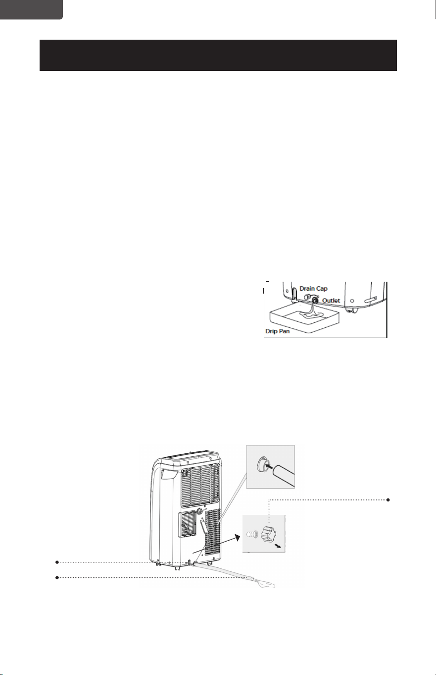
Page 46
FRANÇAIS
CONFIGURATION ET UTILISATION
VIDANGE D’EAU POUR LES MODES FRAIS ET CHALEUR
Ce climatiseur est équipé d’une évaporation automatique de l’eau de sorte que le
compartiment d’eau ne remplirait généralement pas en mode de refroidissement
ou de chauage à moins qu’il y ait une humidité élevée. Le drainage de l’eau ne sera
généralement nécessaire qu’à la fin de la saison pour ces modes (voir OPÉRATIONS
DE DÉBUT-FIN DE SAISON).
REMARQUE: Lorsqu’un code d’erreur apparaît sur l’écran d’achage du panneau de
commande “E2” en mode FRAIS ou DÉSHUMIDIFIER, ou “E4” en mode
CHALEUR, l’unité devra être vidée.
Drainage Intermittent
• Débranchez l’appareil de la source d’alimentation. Déplacez soigneusement
l’appareil vers une zone de drainage au-dessus du plancher de votre sous-sol ou
du bac d’égouttage (non inclus). Enlevez le bouchon de vidange inférieu.
• Laissez l’eau s’écouler et remplacez le bouchon de vidange. Redémarrez la
machine jusqu’à ce que les codes d’erreur E2 ou E4 disparaissent. Si l’erreur se
répète, appelez le service après-vente.
REMARQUE: Assurez-vous de réinstaller le bouchon de vidange inférieur avant
d’utiliser l’appareil.
Drainage Continue
• Débranchez l’appareil de la source d’alimentation. Enlevez le bouchon de
vidange inférieur. Au cours de cette opération, une partie de l’eau résiduelle
peut se déverser. Avoir un bac d’égouttage (non fourni) pour collecter l’eau.
• Branchez le tuyau de vidange (fourni) comme indiqué sur le schéma. L’eau
peut être drainée en continu à travers le tuyau dans un drain de sol ou un bac
d’égouttage.
• Allumez l’appareil.
ATTENDRE 3 MINUTES AVANT DE REPRENDRE L’OPÉRATION
• Une fois l’unité arrêtée, elle ne peut pas être redémarrée pendant 3 minutes.
L’opération redémarre automatiquement après 3 minutes.
Sortie de vidange
Bouchon de
vidange
Tuyau de vidange

Page 47
FRANÇAIS
Drainage Continue pour le Mode De Déshumidification
• Débranchez l’appareil de la source d’alimentation.
• Enlevez le bouchon de vidange situé au centre arrière de l’unité. Au cours de
cette opération, une partie de l’eau résiduelle peut se déverser. Avoir un bac
d’égouttage (non fourni) pour collecter l’eau.
• Branchez le tuyau de vidange (fourni) comme indiqué sur le schéma. L’eau peut
être vidangée en continu à travers le tuyau dans un drain de plancher ou un
seau.
Allumez l’appareil.
CONFIGURATION ET UTILISATION
ATTENDRE 3 MINUTES AVANT DE REPRENDRE L’OPÉRATION
• Une fois l’unité arrêtée, elle ne peut pas être redémarrée pendant 3 minutes.
L’opération redémarre automatiquement après 3 minutes.
Sortie de
vidange
Bouchon de
vidange
Tuyau de vidange
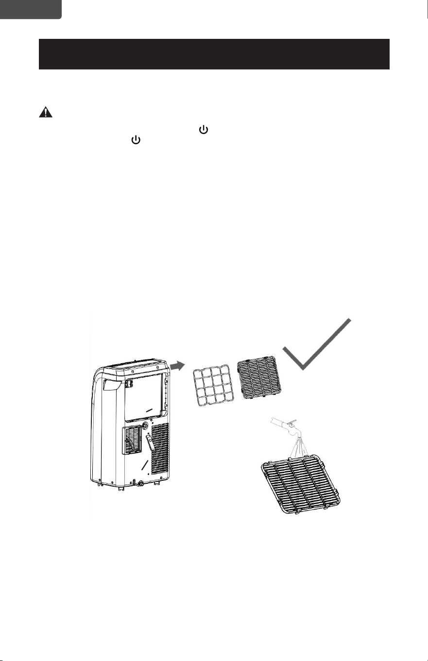
Page 48
FRANÇAIS
NETTOYAGE ET ENTRETIEN
NETTOYAGE
AVERTISSEMENT: Avant le nettoyage ou l’entretien, éteignez l’appareil en
appuyant sur le bouton du panneau de commande ou
sur le bouton de la télécommande. Débranchez la prise
électrique.
NETTOYAGE DU BOÎTIER
Vous devez nettoyer l’appareil avec un chion légèrement humide, puis le sécher
avec un chion sec.
• Ne jamais saturer le climatiseur avec de l’eau.
• N’utilisez jamais d’essence, d’alcool ou de solvants pour nettoyer l’appareil.
• Ne vaporisez jamais d’insecticide liquide ou similaire près du climatiseur.
NETTOYAGE DU FILTRE
Pour que votre climatiseur fonctionne ecacement, vous devez nettoyer le filtre
de l’évaporateur toutes les semaines de fonctionnement.
Le filtre est logé dans la grille d’admission.
Utilisez un aspirateur pour éliminer les accumulations de poussière du filtre.
S’il est très sale, immergez-le dans de l’eau chaude et rincez-le plusieurs fois.
L’eau doit être tiède.
Après le lavage, laissez sécher le filtre, puis réinsérez-le.
OPÉRATIONS DE DÉBUT-FIN DE SAISON
CONTRÔLES DE DÉBUT DE SAISON
Assurez-vous que le câble d’alimentation et la fiche ne sont pas endommagés.
Suivez les instructions d’installation avec précision.
OPÉRATIONS DE FIN DE SAISON
Reportez-vous à la section Drainage d’Eau pour vous assurer que le climatiseur
est complètement vidangé de l’eau.
Nettoyez le filtre et séchez-le soigneusement avant de le réinstaller
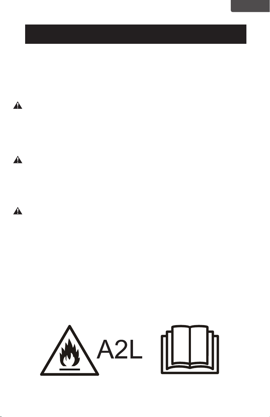
Page 49
FRANÇAIS
DÉPANNAGE ET GARANTIE
AVANT D’APPELER LE SERVICE
SI LE CLIMATISEUR NE FONCTIONNE PAS:
A) Vériez que le climatiseur est bien branché. Si ce n’est pas le cas, enlevez la
che de la prise, attendez 10 secondes et rebranchez-la solidement.
B) Vériez la présence d’un fusible de circuit grillé ou d’un disjoncteur principal
déclenché. Si ceux-ci semblent fonctionner correctement, testez la prise avec
un autre appareil.
AVERTISSEMENT
SI AUCUNE DES SOLUTIONS CI-DESSUS NE RÉSOUT LE PROBLÈME,
CONTACTEZ UN TECHNICIEN QUALIFIÉ. N’ESSAYEZ PAS DE RÉGLER OU DE
RÉPARER LE CLIMATISEUR VOUS-MÊME. Toute personne qui travaille sur un
circuit de réfrigérant ou qui y pénètre doit être titulaire d’un certicat valide
d’une autorité d’évaluation accréditée par l’industrie, qui autorise sa compétence
à manipuler des réfrigérants en toute sécurité conformément à une spécication
d’évaluation reconnue par l’industrie.
AVERTISSEMENT
Ne pas utiliser de moyens pour accélérer le processus de dégivrage ou pour
nettoyer autres que ceux recommandés par le fabricant.
L’appareil doit être rangé dans un local dépourvu de sources d’inammation
fonctionnant en continu (par exemple: ammes nues, appareil à gaz en
fonctionnement ou appareil de chauffage électrique en fonctionnement).
Ne pas percer ou brûler.
Sachez que les réfrigérants peuvent ne pas contenir d’odeur.
AVERTISSEMENT
L’entretien ne doit être effectué que selon les recommandations du fabricant
de l’équipement. L’entretien et la réparation exigeant l’assistance d’un autre
personnel qualié doivent être effectués sous la supervision de la personne
compétente pour l’utilisation des réfrigérants inammables.
SERVICE CLIENT
IMPORTANT
NE PAS RETOURNER CE PRODUIT AU MAGASIN
Si vous avez un problème avec ce produit, veuillez contacter le
Centre de Satisfaction Client W Appliance Co. au
844-299-0879.
PREUVE D’ACHAT DATÉE, NUMÉRO DE MODÈLE ET NUMÉRO
DE SÉRIE REQUIS POUR LE SERVICE DE GARANTIE
Attention: Risque d’incendie/matériaux
inammables (Requis pour les unités
R32/R290 uniquement)
REMARQUE IMPORTANTE: Lisez attentivement ce
manuel avant d’installer ou d’utiliser votre nouvelle
unité de climatisation. Veillez à conserver ce
manuel pour référence ultérieure.
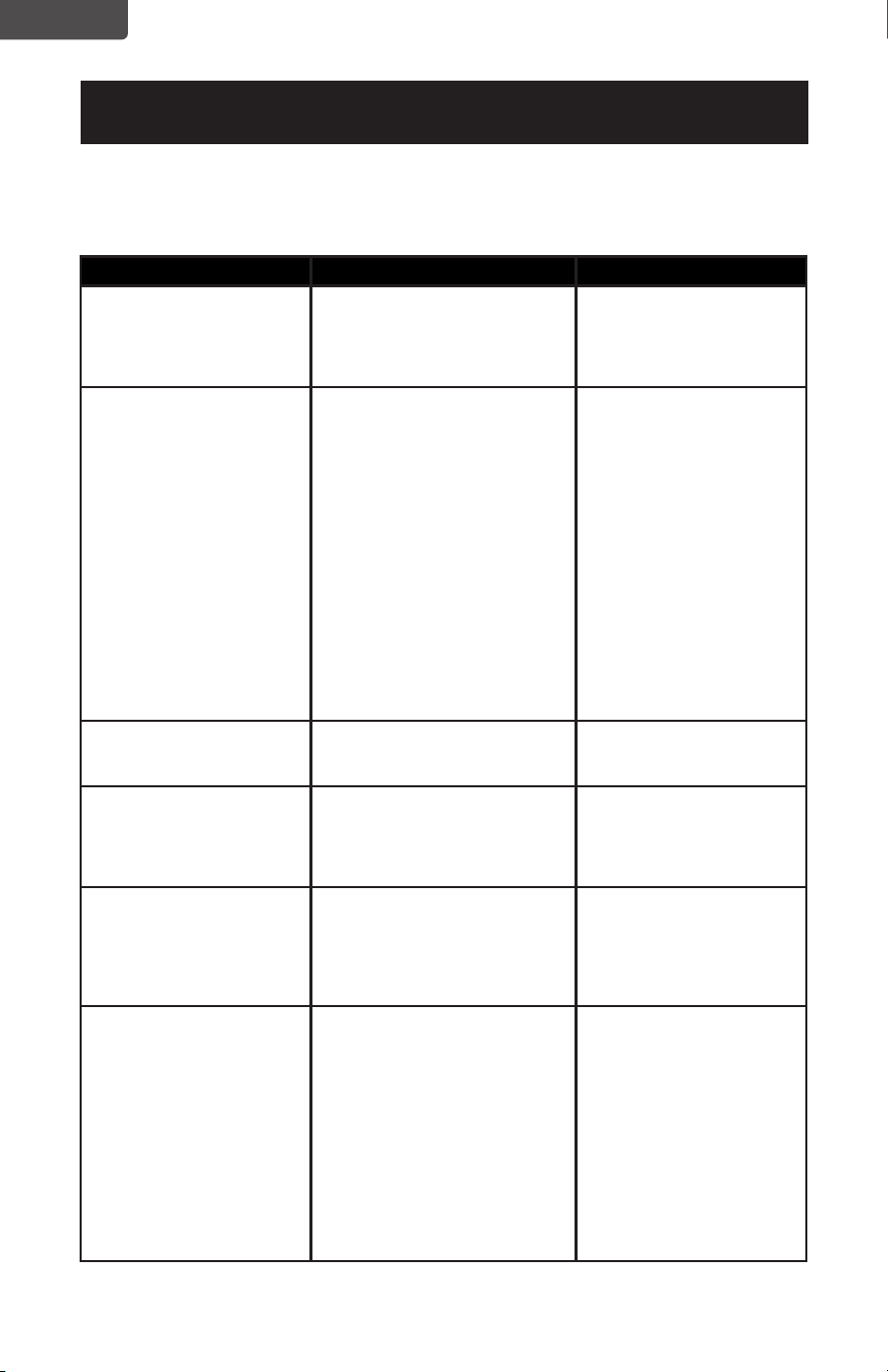
Page 50
FRANÇAIS
DÉPANNAGE ET GARANTIE
Résolvez votre problème en utilisant le tableau ci-dessous. Si le climatiseur ne
fonctionne toujours pas correctement, contactez le centre de service client
BLACK+DECKER ou le centre de service agréé le plus proche. Les clients ne doivent
jamais dépanner les composants internes.
TROUBLE CAUSE POSSIBLE RECOURS POSSIBLE
L’unité ne démarre pas
quand vous appuyez sur le
bouton MARCHE/ARRÊT
A. Le réservoir d’eau peut
être plein si l’afchage DEL
indique “E2” en mode FROID
ou DÉSHUMIDIFIER, ou “E4”
en mode CHALEUR.
A. Vider l’eau
B. Réinitialiser la
température
Pas assez frais A. Les fenêtres ou portes de la
pièce ne sont pas fermées
B. Il y a des sources de chaleur
à l’intérieur de la pièce
C. La conduite d’air
d’échappement n’est pas
raccordée ou obstruée
D. Réglage de la température
trop élevé
E. Le ltre à air est obstrué par
la poussière
F. L’appareil prendra
environ 3 minutes de
fonctionnement avant que le
refroidissement/chauffage
ne se produise.
A. Assurez-vous que
toutes les fenêtres et
portes sont fermées
B. Enlever les sources de
chaleur si possible
C. Raccorder le conduit
et assurez-vous qu’il
peut fonctionner
correctement
D. Diminuer la température
de consigne
E. Nettoyer le ltre à air
F. Une commande par
microprocesseur retarde
le fonctionnement du
compresseur jusqu’à ce
que 3 minutes se soient
écoulées.
Bruit ou vibration A. La surface n’est pas de
niveau ou pas assez plane
A. Placez l’appareil sur
une surface à niveau et
plane si possible
L’appareil ne fonctionne
pas et indique “E2”
en mode FROID ou
DÉSHUMIDIFIER, ou “E4”
en mode CHALEUR.
A. L’unité doit être vidangée. A. Reportez-vous à la
section sur le drainage
de l’eau.
Afchage DEL “E0” , “E1”,
“E3”
A. EO - Problème du capteur
de température ambiante
B. E1- Capteur de température
du condenseur
C. E3- Capteur de température
de l’évaporateur
A. Contactez le Centre de
Satisfaction Client pour
obtenir de l’aide avec le
code d’erreur.
La télécommande ne
fonctionne pas
A. Rien n’apparaît sur l’écran
DEL.
B. La température et les
symboles apparaissent sur
l’écran DEL, mais la sélection
ne peut pas être modiée.
A. Appuyez sur la
touche DEL de la
télécommande. Si elle
ne s’allume pas, changer
les piles.
B. Assurez-vous que
la télécommande
est pointée vers
le récepteur de la
télécommande sur
l’appareil à moins de 23
pieds et qu’il n’y a pas
d’obstruction.

Page 51
FRANÇAIS
DÉPANNAGE ET GARANTIE
GARANTIE LIMITÉE
Tout service de réparation, de remplacement
ou de garantie, ainsi que toutes les questions
concernant ce produit doivent être adressées
à W Appliance Co. au 844-299-0879 depuis
les États-Unis ou Porto Rico.
W Appliance Co. garantit à l’acheteur d’origine que
le produit sera exempt de défauts de matériel, de
pièces et de fabrication pour la période désignée pour
ce produit. La garantie commence le jour de l’achat
du produit et couvre une période allant jusqu’à 1 an
(12 mois) pour la main-d’ œuvre/1 an (12 mois) pour
les pièces (défauts de fabrication uniquement)/et un
total de 5 ans (60 mois) pour la pièce de compresseur
uniquement.
W Appliance Co. accepte de remplacer, à son gré, le
produit défectueux par une unité neuve ou remise
à neuf équivalente à votre achat initial pendant la
période de garantie.
Exclusions: Cette garantie ne s’applique pas à ce qui
suit:
1. Si l’apparence ou l’extérieur du produit
a été endommagé ou détérioré, altéré
ou modié dans sa conception ou sa
construction.
2. Si le numéro de série original du produit
a été modié ou supprimé ou s’il n’est
pas facile de le déterminer.
3. S’il y a des dommages dus à une
surtension de la ligne d’alimentation, des
dommages de l’utilisateur au cordon
d’alimentation CA ou une connexion à
une source de tension incorrecte.
4. Si les dommages sont dus à une
mauvaise utilisation générale, des
accidents ou des actes de Dieu.
5. Si les tentatives de réparation sont
faites par des agents de service non
autorisés, utilisent des pièces autres
que des pièces d’origine ou des pièces
obtenues de personnes autres que des
compagnies de service autorisées.
6. Sur les unités qui ont été transférées du
propriétaire d’origine.
7. Sur les produits qui ont été achetés
comme remis à neuf, comme neuf,
d’occasion, en termes “Tel Quel” ou
“Vente Finale”.
8. Aux produits utilisés dans un cadre
commercial ou locatif.
9. Aux produits utilisés dans des contextes
autres que l’usage domestique ordinaire
ou utilisés autrement que conformément
aux instructions fournies.
10. Aux dommages pour le service appelle
pour les installations incorrectes.
11. Frais de transport et d’expédition liés au
remplacement de l’unité.
12. Appels de service pour vous indiquer
comment utiliser votre produit.
13. Appels de service pour réparer ou
remplacer le fusible de la maison,
réinitialiser le disjoncteur ou corriger le
câblage dans la maison.
LA RÉPARATION OU LE REMPLACEMENT TEL
QUE PRÉVU DANS LA PRÉSENTE GARANTIE est
LE RECOURS EXCLUSIF DU CLIENT; W Appliance
Co. N’EST PAS RESPONSABLE DES DOMMAGES
ACCESSOIRES OU CONSÉCUTIFS EN CAS DE
VIOLATION DE TOUTE GARANTIE EXPRESSE
OU IMPLICITE SUR CE PRODUIT, SAUF DANS LA
MESURE INTERDITE PAR LA LOI APPLICABLE.
TOUTE GARANTIE IMPLICITE DE QUALITÉ
MARCHANDE D’ADAPTATION À UN USAGE
PARTICULIER SUR CE PRODUIT EST LIMITÉE À LA
DURÉE DE LA GARANTIE.
Certains États n’autorisent pas l’exclusion ou la
limitation des dommages accessoires ou consécutifs,
ou la limitation de la durée de la garantie. Dans ces
cas, les exclusions ou limitations ci-dessus peuvent ne
pas s’appliquer à vous. Cette garantie vous donne des
droits légaux spéciques et vous pouvez également
avoir d’autres droits qui varient d’un État à l’autre.
Obtention Du Service: Pour obtenir le service,
la documentation produit, les fournitures ou les
accessoires, veuillez appeler au 844-299-0879 pour
créer un ticket d’échange/réparation. Assurez-vous
de fournir la date d’achat, le numéro de modèle et une
brève description du problème. Notre représentant du
service à la clientèle vous contactera ou vous enverra
des instructions de retour détaillées.
W Appliance Co. ne garantit pas que l’appareil
fonctionnera correctement dans toutes les conditions
environnementales, et ne fait aucune garantie ni
représentation, implicite ou explicite, en ce qui
concerne la qualité, la performance, la qualité
marchande ou l’adéquation à un usage particulier
autre que l’usage identié dans ce manuel d’utilisation.
W Appliance Co. a fait tout son possible pour
s’assurer que le manuel de cet utilisateur est exact et
décline toute responsabilité pour toute inexactitude ou
omission qui pourrait s’être produite. Les informations
contenues dans ce manuel d’utilisation peuvent
être modiées sans préavis et ne représentent pas
un engagement de la part de W Appliance Co. W
Appliance Co. se réserve le droit d’apporter des
améliorations à ce manuel d’utilisation et/ou aux
produits décrits dans ce manuel d’utilisation à tout
moment et sans préavis. Si vous trouvez dans ce
manuel des informations incorrectes, trompeuses ou
incomplètes, veuillez nous contacter au
844-299-0879.
W Appliance Co.
1356 Broadway
New York, NY 10018

Page 52
FRANÇAIS
Cet appareil est conforme à la partie 15 des règles FCC. Son fonctionnement
est soumis aux deux conditions suivantes: (1) cet appareil ne doit pas causer
d’interférences nuisibles et (2) cet appareil doit accepter toute interférence reçue,
y compris les interférences pouvant entraîner un fonctionnement indésirable. Cet
équipement a été testé et jugé conforme aux limites pour un appareil numérique
de classe B, conformément à la partie 15 des règles de la FCC. Ces limites sont
conçues pour fournir une protection raisonnable contre les interférences nuisibles
dans une installation résidentielle. Cet équipement génère, utilise et peut émettre
de l’énergie radiofréquence et, s’il n’est pas installé et utilisé conformément
aux instructions, peut causer des interférences nuisibles aux communications
radio. Cependant, rien ne garantit que l’interférence ne se produira pas dans une
installation particulière. Si cet équipement cause des interférences nuisibles à la
réception de la radio ou de la télévision, ce qui peut être déterminé en éteignant
et en allumant l’équipement, l’utilisateur est encouragé à essayer de corriger
les interférences par une ou plusieurs des mesures suivantes: a) Réorienter ou
déplacer l’antenne de réception. b) Augmenter la séparation entre l’équipement
et le récepteur. c) Connecter l’équipement dans une prise diérente de celle où le
récepteur est connecté. d) Consulter le détaillant ou un technicien
radio/télévision expérimenté pour obtenir de l’aide.
BLACK & DECKER, BLACK+DECKER, les logos BLACK & DECKER et
BLACK+DECKER et les noms de produits ainsi que le schéma de couleurs
orange et noir sont des marques commerciales de The Black & Decker
Corporation, utilisées sous licence. Tous droits réservés.
Le produit dans cette boîte peut différer légèrement de celui sur la photo.
N’affecte pas la fonction. Tous les accessoires illustrés en photographie ne sont
pas inclus dans cet emballage.
Importé par W Appliance, Inc, 1356 Broadway, New York, NY 10018
March 2022 Imprimé en Chine
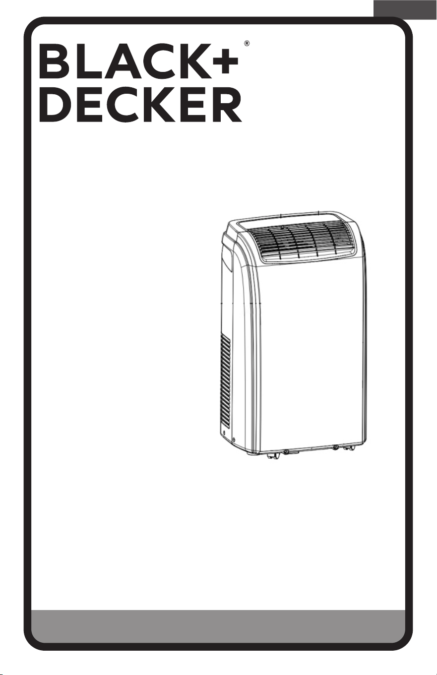
Página 53
ESPAÑOL
MANUAL DE INSTRUCCIONES
AIRE ACONDICIONADO PORTÁTIL
¡Gracias por elegir BLACK+DECKER!
POR FAVOR, LEA ESTE MANUAL ANTES DE DEVOLVER
ESTE PRODUCTO POR CUALQUIER MOTIVO.
Si tiene alguna pregunta o tiene algún problema con su compra de
Black+Decker, vaya a www.blackanddecker.com/instantanswers. Si no puede
encontrar la respuesta o no tiene acceso a Internet, llame al
844-299-0879 de 10:30 a.m. a 6:30 p.m. EST de lunes a viernes para hablar con
un agente. Por favor, tenga el número de catálogo a mano cuando llame.
GUARDE ESTE MANUAL PARA CONSULTARLO
NUEVAMENTE MÁS ADELANTE.
NÚMERO DE CATÁLOGO
BPACT08WT
BPACT10WT
BPACT12WT
BPACT12HWT
BPACT14WT
BPACT14HWT

Página 54
ESPAÑOL
Gracias por comprar nuestro
producto BLACK+DECKER. Este
manual fácil de usar le guiará para
obtener el mejor resultado al usar
su aire acondicionado.
Recuerde anotar los números de
modelo y de serie. Están en una
etiqueta en la parte trasera.
Grape o adjunte su recibo de compra a este
manual.
Lo necesitará para acceder el servicio de
garantía.
Número de modelo
Número de serie
Fecha de compra
REGISTRO DEL PRODUCTO
CONTENIDO
INFORMACIÓN DE SEGURIDAD
Instrucciones importantes de seguridad ............................................................................................................ 55-56
Instrucciones de conexión a tierra ..................................................................................................................................57
Cable de alimentación y enchufe LCDI ............................................................................................................58
Pautas de seguridad ............................................................................................................................................59
Condiciones de funcionamiento ................................................................................................................... 60
CONFIGURACIÓN Y USO
Piezas y características ..........................................................................................................................................................61
Guía de instalación .................................................................................................................................................62
Instalación del kit para ventana deslizante .................................................................................................63
Instalación de la manguera de evacuación ................................................................................................ 64
Panel de control ...................................................................................................................................................65
Operación desde el panel de control .....................................................................................................65-66
Operación desde el control remoto ..............................................................................................................67
Control remoto ................................................................................................................................................68-71
Drenaje de agua ............................................................................................................................................. 72-73
LIMPIEZA Y CUIDADO .................................................................................................................................. 74
RESOLUCIÓN DE PROBLEMAS Y GARANTÍA
Antes de llamar al Servicio Técnico ..................................................................................................................75
Atención al cliente ................................................................................................................................................ 75
Resolución de problemas ..................................................................................................................................76
Garantía limitada ....................................................................................................................................................................77
Página 55
ESPAÑOL
INFORMACIÓN DE SEGURIDAD
INSTRUCCIONES IMPORTANTES DE SEGURIDAD
1. Para reducir el riesgo de lesiones, lea esta guía antes de usar el aparato.
2. El aire acondicionado debe estar conectado a una toma de corriente adecuada con el tipo de
enchufe adecuado y con el suministro eléctrico correcto.
3. Se debe asegurar de que esté debidamente conectado a tierra para reducir el riesgo de
descarga eléctrica e incendio. NO CORTE O QUITE LA PATA DE CONEXIÓN A TIERRA. Si
no tiene una toma de corriente con tres patas, haga que un electricista certicado instale una
toma adecuada. La toma de corriente DEBE estar adecuadamente conectada a tierra.
4. No opere el aire acondicionado si el cable de alimentación está desgastado o dañado de
alguna otra manera. Evite utilizarlo si hay grietas o daños a lo largo del cable, el conector o
si la unidad no funciona bien o está dañada de alguna manera. Contacte al servicio técnico
autorizado para su examinación, reparación o ajuste.
5. NO USE UN ADAPTADOR O UN ALARGUE O REGLETA.
6. No bloquee el ujo de aire alrededor del aire acondicionado. La manguera de evacuación
debe estar libre de obstrucciones.
7. Siempre desconecte el aire acondicionado antes de moverlo o hacerle mantenimiento.
8. No instale o use el aire acondicionado en cualquier zona donde la atmósfera contenga gases
combustibles o donde la atmósfera sea oleosa o sulfurosa. Evite que su aire acondicionado
entre en contacto con cualquier químico.
9. No coloque ningún objeto sobre la unidad.
10. No opere el aire acondicionado sin los ltros en su lugar.
11. No use el aire acondicionado cerca de una bañera, ducha o un lavabo.
12. Este electrodoméstico no está diseñado para ser utilizado por personas con discapacidades
físicas, sensoriales o mentales (incluidos niños) o con falta de experiencia y conocimiento,
a menos que sean supervisados o instruidos acerca del uso del aparato por una persona
responsable de su seguridad.
13. Asegúrese de que los niños no jueguen con el aparato.
14. Si el CABLE DE ALIMENTACIÓN está dañado, debe ser sustituido por el fabricante, su
agente de servicio técnico o una persona de similar cualicación con el n de evitar cualquier
situación de riesgo.
15. El aire acondicionado debe instalarse de acuerdo con las regulaciones nacionales sobre
cableado.
ADVERTENCIA
ADVERTENCIA - Peligros o
prácticas inseguras que PUEDEN
RESULTAR en lesiones personales
graves o la muerte
PELIGRO
PELIGRO - Amenazas inmediatas
que RESULTARÁN en lesiones
personales graves o la muerte
PRECAUCIÓN
PRECAUCIÓN - Peligros o prácticas
inseguras que PODRÍAN resultar en
lesiones personales menores
ADVERTENCIA
Cuando se usen aparatos eléctricos, se deben tomar precauciones de
seguridad básicas, incluidas las siguientes.

Página 56
ESPAÑOL
MANIPULACIÓN DE PILAS ALCALINAS
1. Si el uido de las pilas entrara en contacto con sus ojos accidentalmente, existe el riesgo de
pérdida de la visión, no los frote. Lave inmediatamente sus ojos con agua limpia del grifo y
consulte inmediatamente a un médico.
2. No coloque la pila en el fuego, ni la exponga al calor, ni la desarme, ni la modique.
Si el aislamiento o la válvula de seguridad son dañados, la pila puede perder uido,
sobrecalentarse o explotar.
3. No inserte la pila con los polos invertidos. Hacerlo puede causar una anomalía o un
cortocircuito y la pila puede perder uido, sobrecalentarse o explotar.
4. Mantenga las pilas lejos del alcance de los niños. Si la pila fuese ingerida, contacte a un
médico inmediatamente.
5. Si el uido alcalino entra en contacto con su boca, enjuáguela con agua y contacte a un
médico inmediatamente.
6. Si el uido alcalino entra en contacto con su piel o ropa, puede quemar su piel, enjuague
exhaustivamente el área afectada con agua del grifo.
7. No mezcle pilas nuevas con viejas o otras marcas de pilas. Los atributos diferentes pueden
causar que la pila pierda líquido, se sobrecaliente o explote.
8. Este tipo de pilas no son recargables. Recargar estas pilas puede dañar el aislamiento o
estructura interna y puede causar que la pila pierda líquido, se sobrecaliente o explote.
9. No dañe o quite la etiqueta del exterior de la pila. Hacerlo puede causar que la pila pierda
líquido, se sobrecaliente o explote.
10. No deje caer, tire o exponga a la pila a impactos extremos. Hacerlo puede causar que la pila
pierda líquido, se sobrecaliente o explote.
11. No altere la forma de la pila. Si el aislamiento o la válvula de seguridad son dañados, la pila
puede perder uido, sobrecalentarse o explotar.
12. Quite las pilas inmediatamente cuando hayan perdido toda su carga. Dejar las pilas en la
unidad por un largo tiempo puede causar que las mismas pierdan líquido, se sobrecalienten o
exploten debido al gas generado por las pilas.
13. Quite las pilas de la unidad cuando no esté en uso por un período extendido de tiempo. Las
pilas pueden perder líquido, sobrecalentarse o explotar debido al gas generado por las pilas.
14. No aplique ningún tipo de soldadura directamente sobre las pilas. El calor puede causar que
la pila pierda líquido, se sobrecaliente o explote.
15. No moje las pilas. Hacerlo puede causar que las pilas se sobrecalienten.
16. Guarde las pilas en un lugar fresco y seco alejado de la luz del sol. No hacerlo puede
causar que la pila pierda líquido, se sobrecaliente o explote. Además, puede causar que el
desempeño y vida útil de las pilas se vea afectado.
17. Siga las regulaciones del gobierno local al desechar estas pilas.
18. NUNCA mezcle pilas alcalinas con estándares de carbono-zinc o recargables de níquel-
cadmio en este producto.
CONSERVE ESTAS INSTRUCCIONES
SOLO PARA USO DOMÉSTICO
ADVERTENCIA
Cuando se manipulen pilas alcalinas, se deben tomar precauciones
que deben ser seguidas como se detalla a continuación.
INFORMACIÓN DE SEGURIDAD
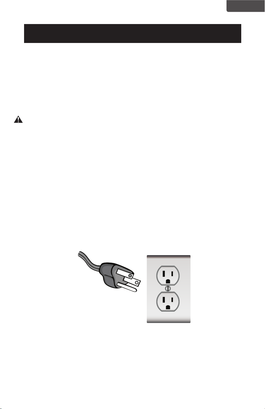
Página 57
ESPAÑOL
INSTRUCCIONES DE CONEXIÓN A TIERRA
REQUISITOS ELÉCTRICOS
En caso de falla o avería, la conexión a tierra proporciona una ruta de menor
resistencia para la corriente eléctrica para reducir el riesgo de descarga eléctrica.
Este aparato debe estar conectado con un cable que posea un conductor de
conexión a tierra y enchufe con conexión a tierra. El enchufe debe ser insertado
en una toma de corriente que esté instalada y conectada a tierra, cumpliendo
todos los códigos y ordenanzas locales.
PELIGRO- Una conexión incorrecta del conductor para la conexión a tierra puede
causar una descarga eléctrica. El conductor con aislamiento de color verde con o
sin franjas amarillas es el conductor de puesta a tierra del equipo. Si es necesario
reparar o reemplazar el cable o el enchufe, no conecte el conductor de puesta
a tierra del equipo a un terminal activo. Consulte a un electricista calificado o
personal de servicio si las instrucciones de conexión a tierra no se comprenden
completamente o si tiene dudas sobre si el electrodoméstico está conectado a
tierra correctamente. No modifique el enchufe que viene con el electrodoméstico.
Si este no encaja en la toma de corriente, pida a un electricista que instale una
toma de corriente adecuada.
PARA ELECTRODOMÉSTICOS CON CONEXIÓN A TIERRA MEDIANTE CABLE
CON CONSUMO NOMINAL INFERIOR A 15 AMPERIOS Y DISEÑADOS PARA SU
USO EN UNA RED ELÉCTRICA DE 120V NOMINALES
El aparato se debe usar en circuito eléctrico con tensión nominal de 120V y
debe estar conectado a una toma con tierra que se parece a la que se ilustra a
continuación. No se recomienda el uso de un adaptador inclusive de forma temporal.
INFORMACIÓN DE SEGURIDAD
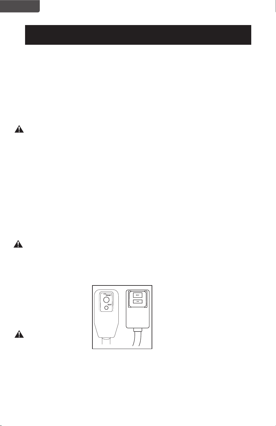
Página 58
ESPAÑOL
INFORMACIÓN DE SEGURIDAD
CABLE DE ALIMENTACIÓN Y ENCHUFE
LCDI
Este aire acondicionado está equipado con un cable de alimentación con LCDI
(Interruptor con Detección de Corriente de Fuga) según lo requerido por
UL. Este cable de alimentación contiene componentes electrónicos de última
generación que detectan la fuga de corriente. Si se daña el cable y se producen
fugas de corriente, se cortará el suministro eléctrico al aparato.
Los botones de prueba y reinicio del enchufe LCDI se utilizan para comprobar si
el enchufe está funcionando correctamente.
ADVERTENCIA: Pruebe el cable LCDI antes de cada uso.
Para probar el enchufe:
1. Enchufe el cable de alimentación en una toma de corriente de 3 clavijas con
conexión a tierra.
2. Presione RESET (en algunas unidades se encenderá una luz verde).
3. Presione el botón TEST, el circuito debería dispararse y cortar toda la energía al
aire acondicionado (en algunas unidades, una luz verde puede apagarse).
4. Presione el botón RESET para poder usar el aparato nuevamente. Oirá un clic y el
aire acondicionado estará listo para usarse nuevamente.
5. Si cuando se presiona el botón de PRUEBA no se interrumpe el suministro
eléctrico al aparato y la unidad no se reinicia, el cable debe ser reemplazado.
NOTA:
• No use este dispositivo para encender o apagar la unidad.
• Asegúrese siempre que el botón RESET esté presionado para una correcta
operación.
ADVERTENCIA:
• Si cuando se presiona el botón de PRUEBA no se interrumpe el suministro eléctrico
al aparato y la unidad no se reinicia, el cable debe ser reemplazado.
• Si el cable de alimentación está dañado, no puede ser reparado.
• Debe ser remplazado por uno obtenido del fabricante del producto.
ADVERTENCIA: RIESGO DE INCENDIO
Es importante que el enchufe se ajuste firmemente a la toma de corriente.
Si el enchufe no se ajusta de manera segura y parece estar flojo, no debe usarse.
Haga que un electricista con licencia reemplace el receptáculo.

Página 59
ESPAÑOL
PAUTAS DE SEGURIDAD
ADVERTENCIA: Para prevenir lesiones al usuario u otras personas y daños a la
propiedad, se deben seguir las instrucciones a continuación. El
uso inadecuado debido a ignorar las instrucciones puede causar
lesiones o daños.
• Su aire acondicionado
debe ser usado de
manera que esté
protegido de la humedad
(p. ej.: condensación,
salpicaduras, etc.). No
coloque o almacene
su aire acondicionado
donde pueda caer o
entrar en contacto con
agua o cualquier otro
líquido. Desenchúfelo
inmediatamente.
• Siempre transporte su aire
acondicionado en posición
vertical y debe reposar
sobre una supercie
estable y nivelada durante
su uso.
• Apague el producto
cuando no se encuentre
en uso.
• Siempre use el interruptor
en el panel de control para
iniciar o detener la unidad.
• Siempre contacte a una
persona calicada para
realizar reparaciones. Si el
cable de alimentación está
dañado, debe ser reparado
por un técnico calicado.
• Mantenga un espacio para
el ujo de aire de al menos
12 pulgadas (30cm) entre
la unidad y las paredes,
muebles y cortinas.
• Si el aire acondicionado es
golpeado durante su uso,
apáguelo y desenchúfelo
inmediatamente.
• No opere su aire
acondicionado en un lugar
húmedo como un baño o un
lavadero.
• No toque la unidad con las
manos mojadas o húmedas o
descalzo.
• No presione los botones del
panel de control con otra
cosa que no sean sus dedos.
• No quite ninguna de las
cubiertas jas. Nunca use
este aparato si no está
funcionando como es debido,
o si ha sido golpeado o
dañado.
• Nunca tire del cable para
detener o iniciar la unidad.
• Siempre use el interruptor en
el panel de control para iniciar
o detener la unidad.
• No cubra u obstruya las
rejillas de entrada o salida.
• No use químicos peligrosos
para limpiar o entrar en
contacto con la unidad. No
use el aparato en presencia
de sustancias o vapores
inamables como alcohol,
insecticidas, nafta, etc.
• No permita a los niños
queuse el aparato sin
supervisión.
• No use este producto para
funciones que no sean otras
que las descritas en este
manual de instrucciones.
• Use el aparato en una habitación
del tamaño recomendado.
8.000 BTU hasta 350 ft
2
10.000 BTU hasta 450 ft
2
12.000 BTU hasta 550 ft
2
14.000 BTU hasta 700 ft
2
• Ubique el aparato de
manera que los muebles no
bloqueen el ujo de aire.
• Mantenga las cortinas y
persianas recogidas.
• Mantenga los ltros
limpios.
• Mantenga las puertas y
ventanas cerradas para
conservar el aire fresco
dentro y evitar que
entre aire cálido.
INFORMACIÓN DE SEGURIDAD
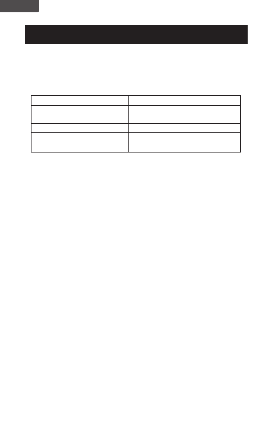
Página 60
ESPAÑOL
CONDICIONES DE FUNCIONAMIENTO
El aire acondicionado debe funcionar dentro del rango de temperatura indicado a continuación:
NOTA: El rendimiento del aparato puede verse afectado cuando se usa fuera de este rango de
temperaturas de funcionamiento.
MODO TEMPERATURA AMBIENTE
ENFRIAR 64˚F (18˚C) ~ 76˚F (24˚C)
(Humedad máxima:75,2°F / 24°C )
SECAR 64˚F (18˚C) ~ 95˚F (35˚C)
CALENTAR(solo modelos con calor:
BPACT12HWT y BPACT14HWT)
45˚F (7˚C) ~ 81˚F (27˚C)
INFORMACIÓN DE SEGURIDAD
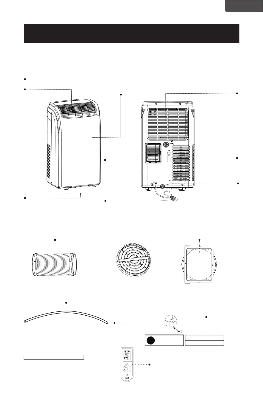
Página 61
ESPAÑOL
PIEZAS Y CARACTERÍSTICAS
Soporte del cable
de alimentación
Cable de alimentación
Drenaje de la
condensación
Desagüe para deshumidicación
Panel de control
Panel frontal
Rejilla
Ducto de evacuación de aire Entrada del ducto
Salida del ducto
Manguera de drenaje
3,3 pies de largo y 0,6
pulgadas de diámetro
Control remoto
Junta de espuma
2 tornillos de jación
CONFIGURACIÓN Y USO
Soporte para ventana
Las conexiones de entrada y salida ya vienen colocadas en el ducto
Salida para el
ducto de
evacuación
de aire
Ruedas giratorias

Página 62
ESPAÑOL
GUÍA DE INSTALACIÓN
UBICACIÓN
• El aire acondicionado debe ser colocado en un piso rme para minimizar el
ruido y las vibraciones. Para un posicionamiento seguro y estable, coloque la
unidad en un piso liso y nivelado lo sucientemente fuerte como para soportar
la unidad.
• La unidad tiene ruedas para ayudar al posicionamiento, pero debe ser movido
sobre supercies lisas y planas. Tenga precaución al moverlo sobre supercies
alfombradas. No intente mover el aparato sobre objetos.
• El aparato debe ser colocado al alcance de una toma de corriente
debidamente conectada a tierra y que soporte los requisitos eléctricos.
• Nunca coloque obstáculos alrededor de la entrada o salida de aire del aparato.
• El aire acondicionado se debe instalar en una supercie plana con espacio libre
alrededor. No bloquee la salida de aire. La el espacio alrededor del aparato
debe ser de al menos 80 cm. La distancia requerida por sobre el aparato debe
ser de al menos 50 cm.
HERRAMIENTAS RECOMENDADAS PARA LA
INSTALACIÓN DEL KIT PARA VENTANA
• Atornilladores (Phillips mediano)
• Cinta métrica o regla
• Cuchillo o tijeras
• Sierra (en caso de que el kit de ventana necesite ser recortado porque la
ventana es muy angosta para la instalación directa)
CONFIGURACIÓN Y USO
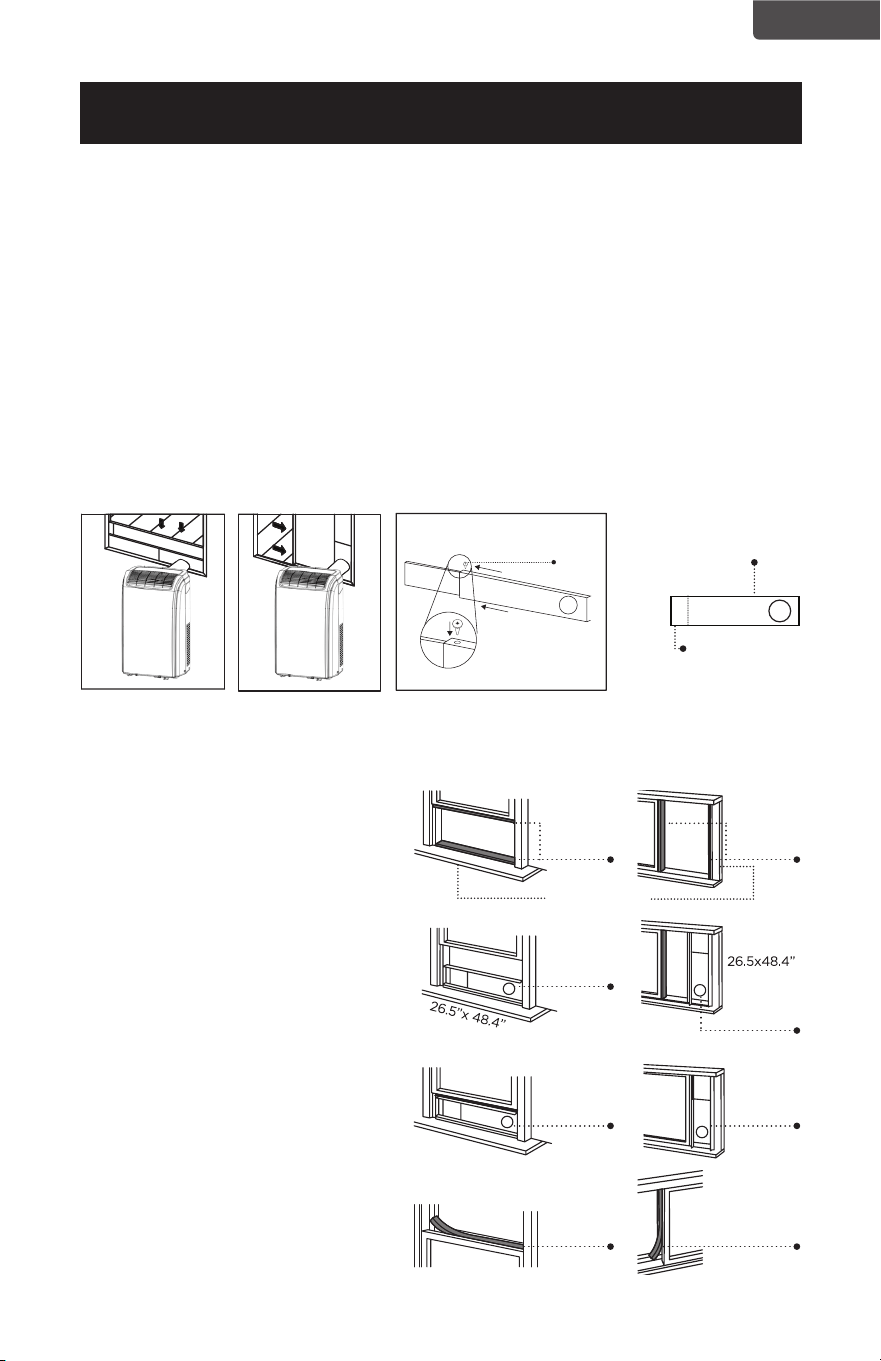
Página 63
ESPAÑOL
INSTALACIÓN DEL KIT PARA VENTANA
Su kit de ventana ha sido diseñado para acomodarse a la mayoría de las
ventanas “horizontales” y “verticales”. Sin embargo, puede ser necesario que
improvise o adapte algunos aspectos del procedimiento de instalación para
ciertos tipos de ventana. Aperturas mínima y máxima de la ventana:
MÁXIMO: 123 CM (48,4”) MÍNIMO: 67,5 CM (26,5”)
NOTA: Un perno de bloqueo de plástico mantiene unido el kit de ventana durante el envío.
Antes de la instalación, retire el perno de bloqueo de plástico, ajuste el kit para
ventana a la longitud deseada y use los tornillos de jación de metal provistos para
asegurar el kit.
NOTA: Si la apertura de la ventana es menor que la longitud mínima del kit para ventana,
corte la parte que tiene un agujero para ajustarla a la apertura de la ventana. Nunca
corte el agujero en el kit para ventana.
CONFIGURACIÓN Y USO
INSTALACIÓN DEL KIT DE VENTANA ABATIBLE O PIVOTANTE
Ventana horizontal Ventana vertical Kit para ventana
El kit para ventana se puede fijar
insertando el tornillo de fijación.
Corte en el lado
opuesto al agujero.
1. Corte el sello de espuma (tipo
adhesivo) a la longitud correcta y
colóquelo en la hoja de la ventana.
2. Fije el kit para ventana a la hoja de
la ventana. Ajuste la longitud del
kit para ventana de acuerdo con
el ancho o la altura de la misma.
Acorte el kit para ventana si el
ancho de la ventana es inferior a
26,5” (67,3cm).
3. Corte el sello de espuma (tipo
adhesivo) a la longitud correcta y
colóquelo en la parte superior de la
ventana.
4. Cierre la ventana de forma ajustada
contra el kit para ventana.
5. Fije el kit para ventana a la hoja de
la ventana.
6. Corte el sello de espuma a una
longitud apropiada y selle la brecha
entre la hoja superior y la hoja
exterior de la ventana.
Tornillo
de
fijación
Junta de
espuma
Junta de
espuma
Junta de
espuma
Junta de
espuma
Kit para
ventana
Kit para
ventana
Kit para
ventana
Kit para
ventana
Hoja de la ventana
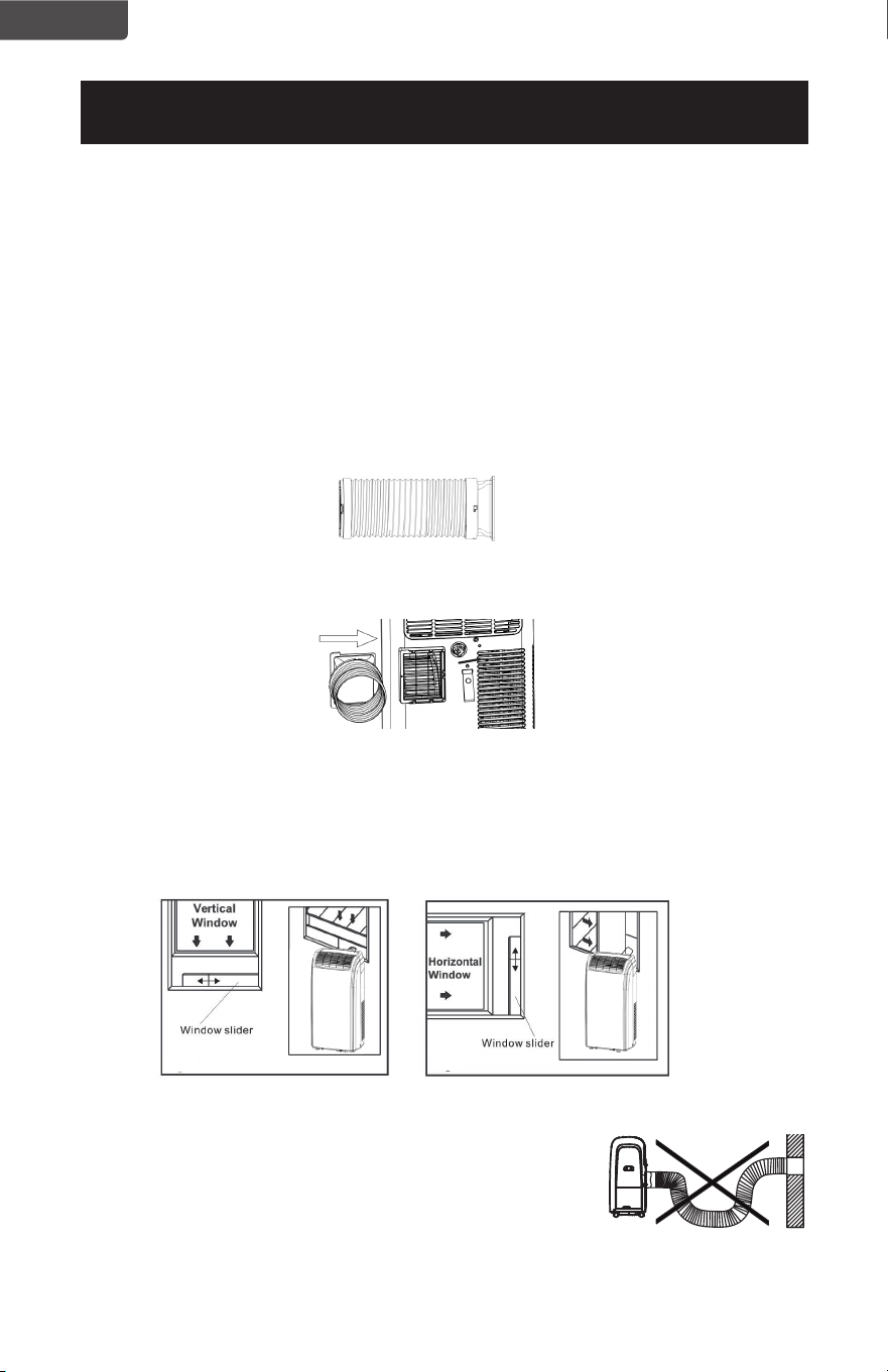
Página 64
ESPAÑOL
INSTALACIÓN DEL DUCTO DE EVACUACIÓN
El ducto de evacuación de aire y la entrada del ducto deben instalarse o retirarse del
aire acondicionado portátil según se esté utilizando:
ENFRIAR, DESHUMIDIFICAR y CALENTAR (solo en modelos con calor:
BPACT12HWT y BPACT14HWT): El ducto de escape de aire y la entrada de
la manguera deben conectarse al aire acondicionado portátil.
VENTILADOR: El ducto de evacuación de aire y la entrada del ducto deben
desconectarse del aire acondicionado.
Para instalar:
1. Las conexiones de entrada y salida ya vienen colocadas en el ducto.
2. Alinee la entrada del ducto con las ranuras de la salida para el ducto de ventilación
en la carcasa del aparato para ensamblarlos.
3. Inserte la salida del ducto en el panel para ventana.
4. Fije la salida del ducto en el kit para ventana y séllelo.
NOTA: El ducto de evacuación puede ser comprimido o
extendido moderadamente, pero se recomienda
mantener su longitud al mínimo. Asegúrese también
de que el ducto no tenga curvas pronunciadas.
CONFIGURACIÓN Y USO
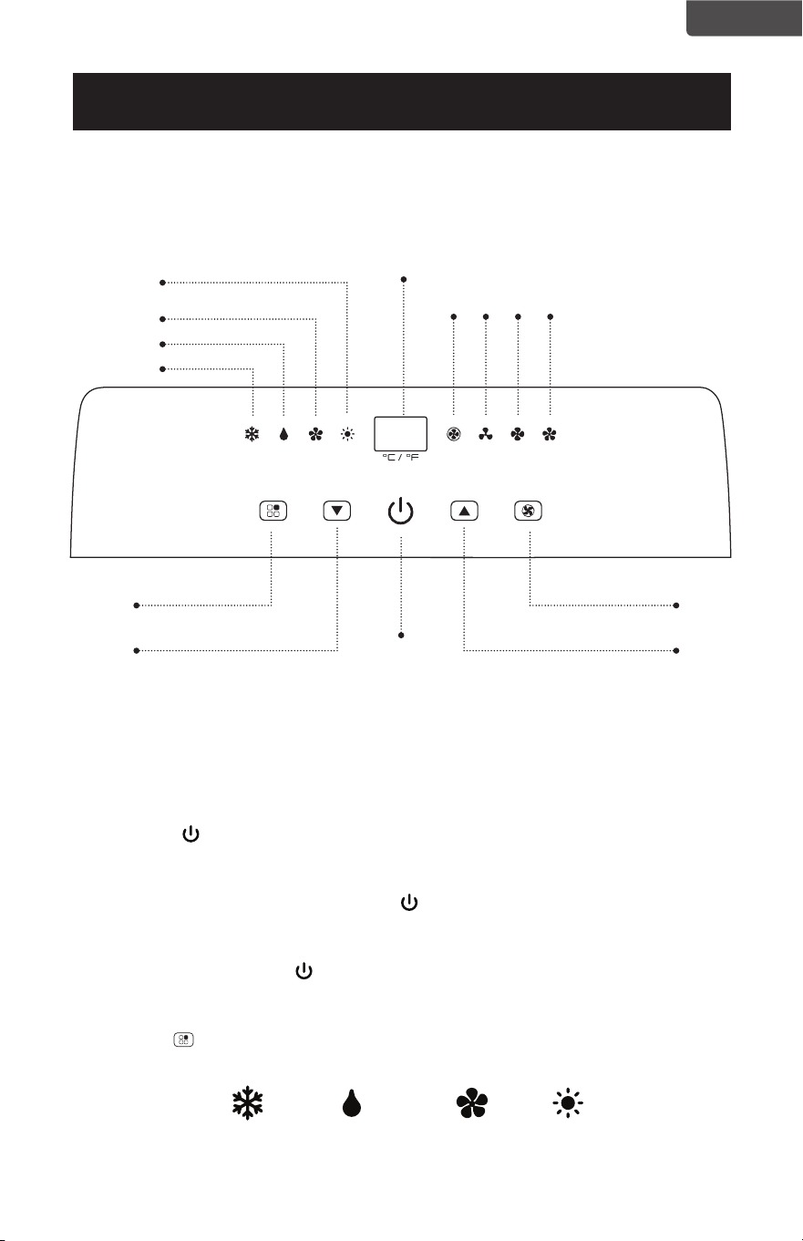
Página 65
ESPAÑOL
PANEL DE CONTROL
CONFIGURACIÓN Y USO
Enfriar
ENFRIAR VENTILADOR CALENTAR DESHUMIDIFICAR
Ventilador
Área de visualización
AUTO
BAJO
MEDIO
ALTO
Deshumidificar
Calentar
(solo modelos con calor:
BPACT12HWT y BPAC-
T14HWT)
Botón de selección
de modo
Botón de selección de
velocidad del ventilador
Botón para subir la
temperatura
ON/OFF
Botón para bajar la
temperatura
Las imágenes son solo para nes ilustrativos. Su modelo puede tener o no todas las
características.
OPERACIÓN DESDE EL PANEL DE CONTROL
El panel de control permite administrar todas las funciones principales del aparato,
pero para aprovechar al máximo su potencial, debe usar el control remoto.
ENCENDER EL APARATO
• Presione el botón hasta que elaparato se encienda. Aparecerá la última
función activa cuando se apagó.
• Nunca apague el aire acondicionado desenchufándolo de la toma de corriente.
Siempre presione el botón de encendido , luego espere unos minutos antes de
desenchufarlo. Esto permite que el aparato realice comprobaciones para verificar el
funcionamiento.
NOTA: Antes de presionar el botón de encendido, asegúrese de que el tapón del
drenaje de condensación en la parte trasera del aparato esté firmemente en su
lugar para evitar pérdidas.
• Presione el botón MODE hasta que se encienda el indicador correspondiente al
modo deseado.
*solo modelos con calor: BPACT12HWT y BPACT14HWT
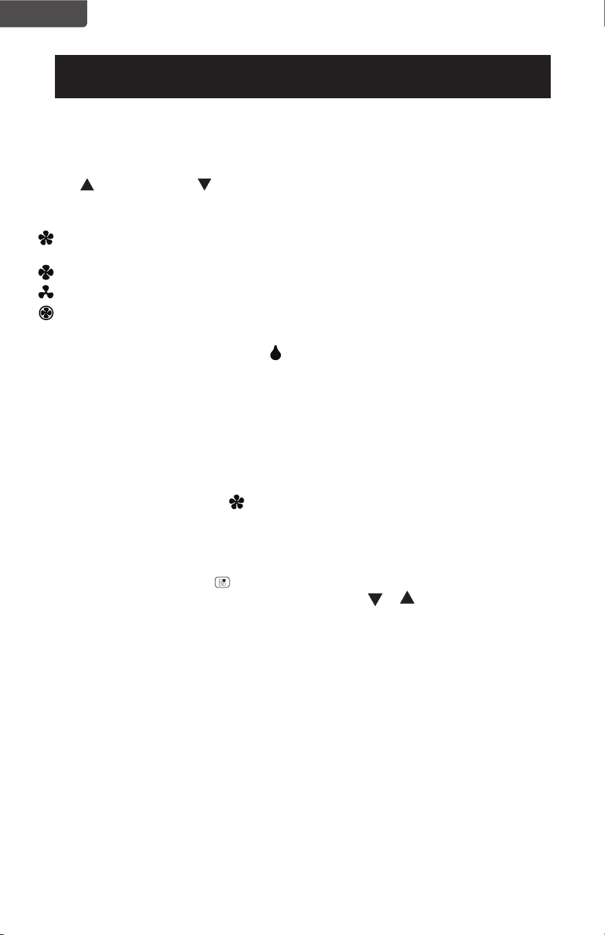
Página 66
ESPAÑOL
CONFIGURACIÓN Y USO
MODO ENFRIAR
Ideal para tiempo caluroso cuando necesita enfriar y deshumidificar la habitación.
Para ajustar correctamente el funcionamiento del aparato, pulse los botones “Temp
Up” o “Temp Down” hasta que se muestre la temperatura deseada.
A continuación, seleccione la velocidad del ventilador pulsando el botón “Fan Speed”
hasta que se encienda el indicador correspondiente a la velocidad deseada:
HIGH: El ventilador funciona al máximo para alcanzar la temperatura deseada lo más
rápidamente posible.
MED: Reduce el nivel de ruido del ventilador, pero mantiene un buen nivel de confort.
LOW: Para un funcionamiento silencioso.
AUTO: El aparato selecciona la velocidad del ventilador más adecuada en relación
con la temperatura configurada en la pantalla digital.
MODO DESHUMIDIFICAR
Ideal para reducir la humedad en primavera y otoño, durante períodos de lluvia o en
habitaciones húmedas, etc.
Se recomienda usar la manguera de drenaje para una deshumidicación más
efectiva, pero no es obligatorio hacerlo.
En el modo de deshumidicación, la velocidad del ventilador se ajusta
automáticamente a una velocidad baja y no se puede cambiar manualmente.
Cuando aparezca el código de error “E2” en la pantalla del panel de control, deberá
drenar el depósito del aparato.
MODO VENTILADOR
Pulse el botón de modo hasta que se encienda el indicador del modo ventilador.
Presiones el botón de velocidad para elegir la velocidad del ventilador.
MODO CALENTAR (solo modelos con calor: BPACT12HWT y BPACT14HWT)
Presione el botón de modo hasta que la luz indicadora HEAT se encienda.
Seleccione la temperatura deseada pulsando el botón o hasta que se muestre
el valor correspondiente (el rango de temperatura es de 61°F a 88°F (16°C a 31°C).
A continuación, seleccione la velocidad del ventilador pulsando el botón “Fan Speed”
hasta que se encienda el indicador correspondiente a la velocidad deseada: HIGH,
MED, LOW, AUTO.
NOTA: Al principio de este modo, es posible que tenga que esperar unos segundos
antes de que el aparato comience a emitir aire caliente.
Cuando aparezca el código de error “E4” en la pantalla de visualización en el modo
CALOR, deberá drenar el depósito del aparato.
NOTA: La velocidad AUTO solo se puede seleccionar mediante el panel de control.

Página 67
ESPAÑOL
CONFIGURACIÓN Y USO
OPERACIÓN DESDE EL CONTROL REMOTO
INSTALACIÓN DE LAS PILAS (NO INCLUIDAS)
(1) Deslice la tapa del compartimiento de las pilas.
(2) Inserte 2 pilas “AAA” como se muestra.
(3) Deslice la tapa del compartimiento de las pilas hacia su posición cerrada.
PRECAUCIÓN: Use solamente pilas alcalinas AAA o IEC R03 de 1,5V. Quite las pilas
si el control remoto no será usado durante un mes o más. No intente recargar las
pilas. Ambas pilas deben ser remplazadas a la vez. No deseche las pilas en el fuego
ya que pueden explotar.
Apunte el control remoto al receptor del aparato. El control remoto no debe estar a
más de 7 metros del aparato (sin obstáculos entre el control remoto y el receptor).
El control remoto debe manipularse con sumo cuidado. No lo deje caer ni lo
exponga a la luz solar directa o a fuentes de calor.
23 Feet

Página 68
ESPAÑOL
CONTROL REMOTO
CONFIGURACIÓN Y USO
Señal remota
Enfriar
Deshumidificar
Ventilador
Temporizador
Botón selector °F
Botón aumentar
Botón selector °C
Botón de encendido/
apagado de la luz
Botón de selección de
velocidad del ventilador
Botón de dormir
Velocidad del ventilador
Dormir
Botón disminuir
Botón de modo
Botón del temporizador
Botón de encendido
Calentar
(solo modelos con calor:
BPACT12HWT y BPACT14HWT)
BOTÓN DE ENCENDIDO: presione para encender o apagar
BOTÓN TIMER: Se utiliza para establecer una hora de inicio o apagado diferido.
BOTÓN DE MODO: Presiónelo para elegir entre por ENFRIAR, DESHUMIDIFICAR,
VENTILADOR o CALENTAR (solo en los modelos BPACT12HWT
y BPACT 14HWT).
BOTÓN SELECTOR °C: Muestra la temperatura en °C
BOTÓN SELECTOR °F: Muestra la temperatura en °F
AUMENTAR: Aumenta el ajuste de temperatura.
DISMINUIR: Disminuye el ajuste de temperatura.
BOTÓN DE ENCENDIDO/APAGADO DE LA LUZ: Ilumina la pantalla LED del aparato.
BOTÓN DE VELOCIDAD DEL VENTILADOR: Úselo para seleccionar la velocidad del
ventilador entre baja, media o alta.
BOTÓN DE DORMIR: Ajusta la temperatura gradualmente.

Página 69
ESPAÑOL
CONFIGURACIÓN Y USO
Swing
BPP08HWTB and
BPP10HWTB only
BOTÓN DE ENCENDIDO
• Presiónelo para ENCENDER o APAGAR el aire acondicionado. Presione el botón
LED para iluminar la pantalla LED de la unidad.
•
Se mostrará en la pantalla LED del control remoto para indicar que se está
emitiendo una señal hacia el aire acondicionado.
BOTÓN DE MODO
• Presione el botón de modo para elegir entre ENFRIAR , DESHUMIDIFICAR ,
VENTILADOR , CALENTAR (solo modelos con calor BPACT12HWT y
BPACT14HWT).
• El símbolo correspondiente se iluminará en la pantalla LED para indicar qué
modo está seleccionado.
ENFRIAR
• Seleccione la temperatura deseada entre 61°F y 88°F (16°C y 31°C) presionando
los botones + o - hasta que se muestre la temperatura deseada en la pantalla
LED.
• Presione el botón “Fan Speed” para escoger entre velocidad baja, media, o alta.
BPACT12HWT y
BPACT14HWT solamente
Mostrar temperatura
u horas
Modo enfriar
Velocidad del
ventilador
Temporizador
encendido
Dormir
Fahrenheit o Celsius.
Modo calentar
Modelos con calor
Modo ventilador
Modo deshumidificar
Temporizador
Indicadores de la pantalla LED
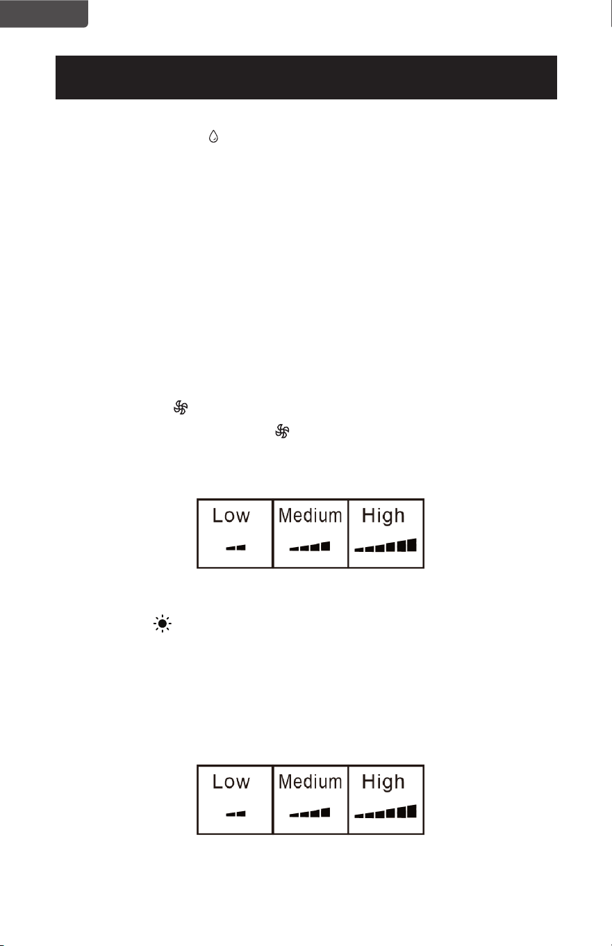
Página 70
ESPAÑOL
CONFIGURACIÓN Y USO
DESHUMIDIFICAR
• Ideal para reducir la humedad.
• Mantenga las ventanas y puertas cerradas para un mejor efecto deshumidificador.
• En este modo no se requiere el uso de la manguera de drenaje pero se recomienda
para una deshumidificación más efectiva.
• Se recomienda que se use la manguera de drenaje para un uso continuo.
• DEPÓSITO LLENO: Cuando aparezca el código de error “E2” en la pantalla del panel
en el modo ENFRIAR o DESHUMIDIFICAR, o “E4” en el modo CALENTAR, deberá
drenar el depósito del aparato.
NOTA: Consulte la sección “drenaje de agua”
• En este modo, el aparato selecciona automáticamente la velocidad del ventilador y
no se puede configurar manualmente.
VENTILADOR
• Presione el botón “Fan Speed” para escoger entre velocidad baja, media o alta.
CALENTAR (solo modelos con calor: BPACT12HWT y BPACT14HWT)
• Seleccione la temperatura deseada entre 61°F y 88°F (16°C y 31°C) presionando los
botones + o - hasta que se muestre la temperatura deseada en la pantalla LED.
• Presione el botón “Fan Speed” para escoger entre velocidad baja, media, o alta.
NOTA: Al principio de este modo, es posible que tenga que esperar unos segundos
antes de que el aparato comience a emitir aire caliente.

Página 71
ESPAÑOL
CONFIGURACIÓN Y USO
TEMPORIZADOR
• Para configurar el temporizador de PARADA AUTOMÁTICA. Cuando el aparato esté
ENCENDIDO, presione el botón del TEMPORIZADOR. El símbolo de ENCENDIDO/
APAGADO en la pantalla LCD del control remoto parpadeará.
• Pulse el botón + o – para seleccionar el TEMPORIZADOR en incrementos de 1 hora,
hasta La pantalla LCD del control remoto indicará la hora seleccionada. Presione el
botón de TEMPORIZADOR de nuevo para ajustar el tiempo seleccionado. Se
encenderá el indicador de TIEMPO DE ENCENDIDO/APAGADO en la pantalla LCD
remota y la luz indicadora del TEMPORIZADOR se iluminará en el panel de control
del aparato para mostrar que se ha iniciado el programa de APAGADO
AUTOMÁTICO.
• Para configurar el temporizador de ENCENDIDO AUTOMÁTICO. Cuando el aparato
esté APAGADO, presione el botón del TEMPORIZADOR. El símbolo de ENCEN-
DIDO/APAGADO en la pantalla LCD del control remoto parpadeará.
• Pulse el botón + o – para seleccionar el TEMPORIZADOR en incrementos de 1 hora,
hasta La pantalla LCD del control remoto indicará la hora seleccionada. Presione el
botón de TEMPORIZADOR de nuevo para ajustar el tiempo seleccionado. Se
encenderá el indicador de TIEMPO DE ENCENDIDO/APAGADO en la pantalla LCD
del control remoto y la luz indicadora del TEMPORIZADOR se iluminará en el panel
de control del aparato para mostrar que se ha iniciado el programa de INICIO
AUTOMÁTICO.
• Al presionar el botón de ENCENDIDO o el botón del TEMPORIZADOR, se cancelará
el programa de INICIO/APAGADO AUTOMÁTICO y la luz indicadora del
temporizador se apagará.
DORMIR
• La función DORMIR ajusta gradualmente la temperatura de las habitaciones para
proporcionar un ambiente confortable. Presione el botón SLEEP para activar este
modo.
• En el modo ENFRIAR, la temperatura aumentará 2°F después de una hora y 4°F
después de 2 horas.
• En el modo CALENTAR, la temperatura bajará 2°F después de una hora y 4°F
después de 2 horas.
• Para cancelar esta configuración, pulse de nuevo el botón de DORMIR.
BOTÓN SELECTOR °C/°F
• Cuando el aparato esté encendido, pulse el botón selector de °F para mostrar la
temperatura en Fahrenheit.
• Pulse el botón selector de °C para mostrar la temperatura en grados Celsius.
°
F

Página 72
ESPAÑOL
CONFIGURACIÓN Y USO
DRENAJE DE AGUA PARA LOS MODOS ENFRIAR Y CALENTAR
Este acondicionador de aire está equipado con evaporación automática del agua, por lo
que el depósito de agua no se suele llenar en los modos de enfriar o calentar a menos
que haya mucha humedad. El drenaje de agua generalmente solo será necesario al final
de la temporada (ver OPERACIONES DE INICIO Y FIN DE TEMPORADA).
NOTA: Cuando aparezca el código de error “E2” en la pantalla del panel en el modo
ENFRIAR o DESHUMIDIFICAR, o “E4” en el modo CALENTAR, deberá drenar el
depósito del aparato.
Drenaje intermitente
• Desenchufe la unidad de la corriente eléctrica. Mueva el aparato cuidadosamente
a un área con un desagüe en el piso sótano o use una bandeja de goteo (no
incluida). Retire la tapa del desagüe inferior.
• Deje que el agua se drene y tape el desagüe con su tapa una vez completado.
Reinicie la máquina hasta que desaparezcan los códigos de error E2 o E4. Si el
error persiste, llame al servicio técnico.
NOTA: Asegúrese de volver a colocar el tapón del desagüe en la parte inferior antes
de usar el aparato.
Drenaje continuo
• Desenchufe la unidad de la corriente eléctrica. Retire la tapa del desagüe
inferior. Al hacerlo es posible que se derrame algo de agua residual. Tenga una
bandeja de goteo a mano (no suministrada) para recoger el agua.
• Conecte la manguera de drenaje (incluida) como se muestra en el diagrama.
El agua se puede drenar continuamente a través de la manguera en un
desagüe de piso o una bandeja de goteo.
• Encienda la unidad.
ESPERE 3 MINUTOS ANTES DE REANUDAR LA OPERACIÓN
• Una vez que el aparato se detiene no se puede reiniciar durante 3 minutos.
El funcionamiento se reanudará automáticamente luego de 3 minutos.
Salida del desagüe
Tapa del desagüe
Manguera de drenaje
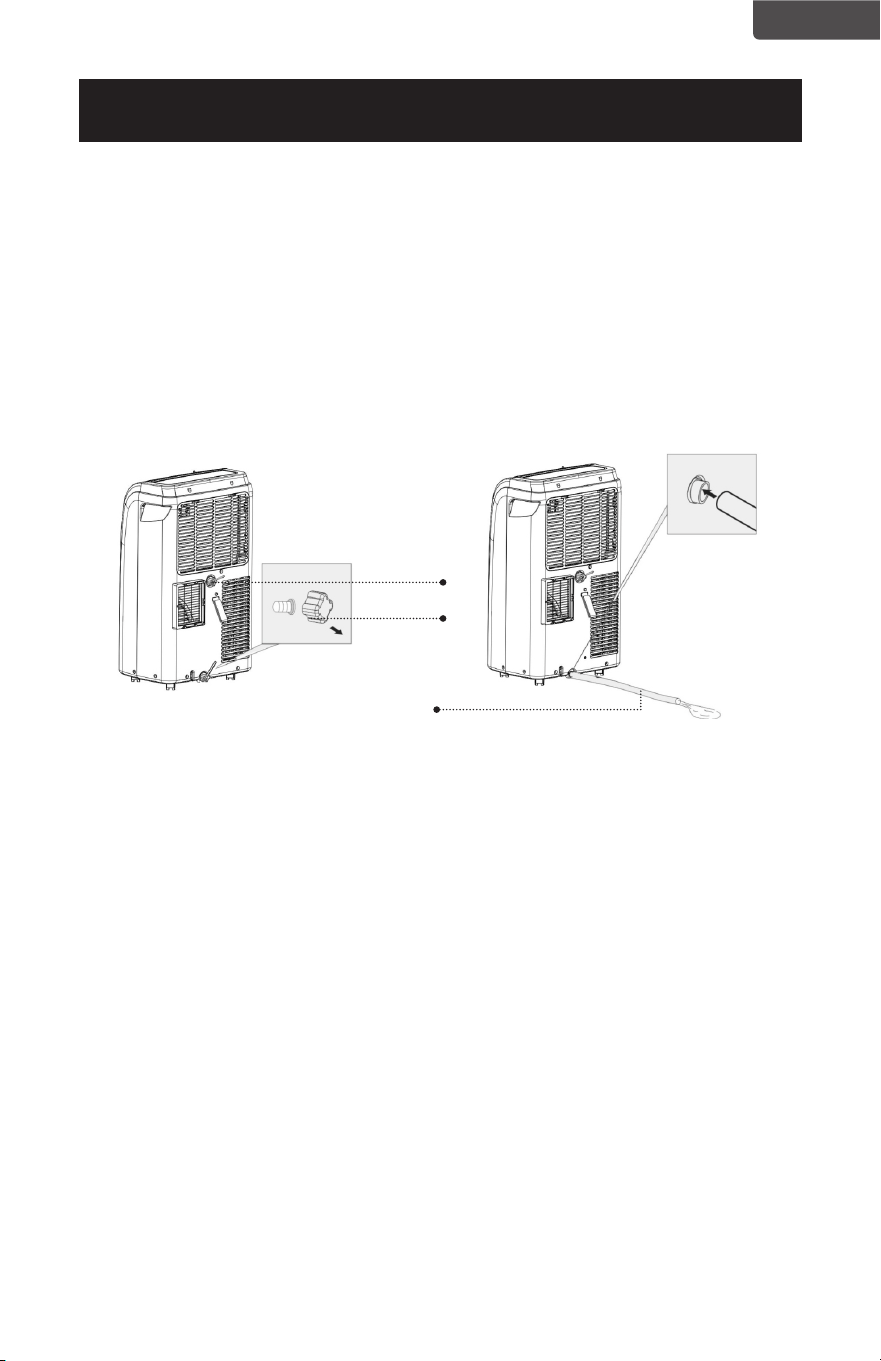
Página 73
ESPAÑOL
Drenaje continuo para el modo de deshumidificación
• Desenchufe la unidad de la corriente eléctrica.
• Retire la tapa del desagüe ubicado en la parte trasera central de la unidad. Al
hacerlo es posible que se derrame algo de agua residual. Tenga una bandeja de
goteo a mano (no suministrada) para recoger el agua.
• Conecte la manguera de drenaje (incluida) como se muestra en el diagrama. El
agua se puede drenar continuamente a través de la manguera en un desagüe de
piso o una bandeja de goteo.
Encienda la unidad.
CONFIGURACIÓN Y USO
ESPERE 3 MINUTOS ANTES DE REANUDAR LA OPERACIÓN
• Una vez que el aparato se detiene no se puede reiniciar durante 3 minutos.
El funcionamiento se reanudará automáticamente luego de 3 minutos.
Salida del
desagüe
Tapa del
desagüe
Manguera de drenaje

Página 74
ESPAÑOL
LIMPIEZA Y CUIDADO
LIMPIEZA
ADVERTENCIA: Antes de la limpieza o el mantenimiento, apague el aparato
presionando el botón en el panel de control o el botón en el
control remoto. Desconéctelo de la toma de corriente.
LIMPIEZA DEL GABINETE
Debe limpiar el aparato con un paño ligeramente humedecido y luego secarlo
con un trapo seco.
• Nunca empape el aire acondicionado.
• No utilice nunca gasolina, alcohol o disolventes para limpiar el aparato.
• Nunca rocíe líquidos insecticidas o similares cerca del aire acondicionado.
LIMPIEZA DEL FILTRO
Para mantener el aire acondicionado funcionando de manera eficiente, debe
limpiar el filtro del evaporador cada semana de funcionamiento.
El filtro está alojado en la rejilla de entrada.
Utilice una aspiradora para eliminar la acumulación de polvo del filtro.
Si está muy sucio, sumérjalo en agua tibia y enjuáguelo varias veces.
El agua debe estar tibia.
Después del lavado, deje que el filtro se seque y vuelva a insertarlo una vez seco.
OPERACIONES DE INICIO/FIN DE TEMPORADA
COMPROBACIONES DE INICIO DE TEMPORADA
Asegúrese de que el cable de alimentación y el enchufe no estén dañados.
Siga las instrucciones de instalación con precisión.
OPERACIONES DE FIN DE TEMPORADA
Consulte la sección Drenaje de Agua para asegurarse de que el aire acondicionado
esté completamente drenado.
Limpie el filtro y séquelo bien antes de volver a instalarlo
Página 75
ESPAÑOL
RESOLUCIÓN DE PROBLEMAS Y GARANTÍA
ANTES DE LLAMAR AL SERVICIO TÉCNICO
SI EL AIRE ACONDICIONADO NO FUNCIONA:
A) Asegúrese de que el aparato está enchufado rmemente. Si no lo está, retire
el enchufe de la toma de corriente, espere 10 segundos y vuelva a conectarlo
rmemente.
B) Compruebe si hay un fusible quemado o un disyuntor principal disparado. Si
éstos funcionan correctamente, pruebe el enchufe con otro electrodoméstico.
ADVERTENCIA
SI NINGUNO DE LOS RESULTADOS ANTERIORES RESUELVE EL PROBLEMA,
COMUNÍQUESE CON UN TÉCNICO CALIFICADO. NO INTENTE AJUSTAR O
REPARAR EL AIRE ACONDICIONADO POR USTED MISMO. Toda persona
que trabaje en un circuito de refrigerante debe tener un certicado vigente y
válido emitido por una autoridad de evaluación acreditada por la industria, que
certique su competencia para manipular refrigerantes de forma segura de
conformidad con una especicación de evaluación reconocida por la industria.
ADVERTENCIA
No utilice medios para acelerar el proceso de descongelación o para limpiar que
no sean los recomendados por el fabricante.
El aparato se deberá almacenar en un local sin llamas abiertas, aparatos de gas
en funcionamiento o un calentador eléctrico en funcionamiento, por ejemplo.
No perforar ni quemar.
Tenga en cuenta que los refrigerantes pueden no tener olor.
ADVERTENCIA
El servicio técnico deberá ser ejecutado según lo recomendado por el fabricante
del aparato. El mantenimiento y las reparaciones que requieran la asistencia
de otro personal calicado se llevarán a cabo bajo la supervisión de la persona
competente en el manejo de refrigerantes inamables.
SERVICIO AL CLIENTE
IMPORTANTE
NO DEVUELVA ESTE PRODUCTO A LA TIENDA
Si tiene problemas con este producto, por favor contacte al
Centro de Satisfacción del Cliente de W Appliance Co. a través
del 844-299-0879.
UNA PRUEBA DE COMPRA CON FECHA, #DE MODELO Y # DE
SERIE ES REQUERIDO PARA EL SERVICIO DE GARANTÍA
Precaución: Riesgo de incendio / materiales
inamables (Requerido solo para unidades
R32/R290)
NOTA IMPORTANTE: Lea este manual
detenidamente antes de instalar u operar
su nuevo aparato de aire acondicionado.
Asegúrese de guardar este manual para
consultarlo nuevamente más adelante.

Página 76
ESPAÑOL
RESOLUCIÓN DE PROBLEMAS Y GARANTÍA
Solucione su problema utilizando el cuadro a continuación. Si el are acondicionado
aún no funciona correctamente, comuníquese con el centro de servicio al cliente de
BLACK+DECKER o con el centro de servicio autorizado más cercano. Los clientes
nunca deben solucionar problemas de componentes internos.
PROBLEMA POSIBLE CAUSA POSIBLE SOLUCIÓN
El aparato no se inicia al
presionar el botón ON/
OFF
A. El depósito de agua
puede estar lleno si la
pantalla LED muestra “E2”
en el modo ENFRIAR o
DESHUMIDIFICAR, o “E4” en
el modo de CALENTAR.
A. Drene el agua
B. Restablezca la
temperatura
No está lo sucientemente
frío
A. Las ventanas o puertas de la
habitación están abiertas
B. Hay fuentes de calor dentro
de la habitación
C. El ducto de evacuación del
aire no está conectado o
está bloqueado
D. El ajuste de temperatura es
demasiado alto
E. El ltro de aire está cubierto
de polvo
F. El aparato tardará
aproximadamente 3 minutos
en comenzar a enfriar o
calentar.
A. Asegúrese de que todas
las ventanas y puertas
estén cerradas
B. Retire las fuentes de
calor de ser posible
C. Conecte el ducto y
asegúrese de que pueda
funcionar correctamente
D. Disminuya la
temperatura
E. Limpie el ltro de aire
F. Un control por
microprocesador retrasa
el funcionamiento del
compresor hasta que
hayan pasado 3 minutos.
Ruido o vibración A. La supercie no está
nivelada o no es lo
sucientemente plana
A. Coloque la unidad en
una supercie plana y
nivelada de ser posible
El aparato no funciona
e indica "E2" en el
modo ENFRIAR o
DESHUMIDIFICAR, o "E4"
en el modo CALENTAR.
A. Se necesita drenar e
depósito de agua.
A. Consulte la sección
“drenaje de agua”
La pantalla LED muestra
los códigos de error "E0",
"E1" o "E3".
A. E0: Problema del sensor de
temperatura ambiente
B. E1: Sensor de temperatura
del condensador
C. E3: Sensor de temperatura
del evaporador
A. Póngase en contacto
con el Centro de
Satisfacción del Cliente
para obtener ayuda con
el código de error.
El control remoto no
funciona
A. No aparece nada en la
pantalla LED.
B. La temperatura y los
símbolos aparecen en la
pantalla LED, pero no se
puede cambiar la selección.
A. Pulse el botón LED del
control remoto. Si no se
ilumina, cambie las pilas.
B. Asegúrese de que el
control remoto esté
apuntando al receptor
en el aparato a una
distancia menor que 23
pies y de que no haya
obstrucciones.

Página 77
ESPAÑOL
RESOLUCIÓN DE PROBLEMAS Y GARANTÍA
GARANTÍA LIMITADA
Cualquier reparación, recambio, o servicio
de garantía, y todas las preguntas sobre este
producto deben ser dirigidas a W Appliance
Co. al 844-299-0879 desde EE.UU. o Puerto
Rico.
W Appliance Co. garantiza al comprador original
que el producto estará libre de defectos de material,
piezas y mano de obra durante el período designado
para este producto. La garantía comienza el día en
que se compra el producto y cubre hasta un período
de 1 año (12 meses) por mano de obra, 1 año (12
meses) por piezas (solo defectos de fabricación)/
reparación en tienda y un total de 5 años (60 meses)
solamente por el compresor.
W Appliance Co. acepta que, de acuerdo con su
criterio, remplazará el producto defectuoso por
uno nuevo o uno remanufacturado equivalente a su
compra original durante el período de garantía.
Exclusiones: esta garantía no aplica a lo
siguiente:
1. Si la apariencia o el exterior
del producto ha sido dañado o
desgurado, alterado o modicado en
el diseño o la construcción.
2. Si el número de serie original del
producto ha sido alterado o removido
o no puede ser determinado
fácilmente.
3. Si hay daños debido a sobretensión en
la línea eléctrica, daño por parte del
usuario al cable de alimentación de CA
o conexión a una fuente de voltaje no
adecuada.
4. Si el daño se debe a mal uso general,
accidentes o actos de Dios.
5. Si existen intentos de reparación
por parte de agentes de servicio no
autorizados, uso de partes que no sean
originales u obtenidas de personas
que no sean las compañías de servicio
autorizadas.
6. En unidades que han sido transferidas
desde el propietario original.
7. A productos que hayan sido
comprados como renovados, como
nuevos, de segunda mano, en términos
de venta nal o “como se ve”.
8. A productos usados en un entorno
comercial o de alquiler.
9. A productos usados en entornos
que no sean el doméstico ordinario
o usados de otra manera que no sea
de acuerdo con las instrucciones
brindadas.
10. A los daños por servicios e
instalaciones incorrectas.
11. A costos de transporte y envío
asociados con el reemplazo de la
unidad.
12. A llamadas de servicio para instruirlo
sobre cómo usar su producto.
13. Llamadas de servicio técnico para
reparar o reemplazar el fusible de
la casa, restablecer el disyuntor o
corregir el cableado de la casa.
LA REPARACIÓN O EL REEMPLAZO SEGÚN LO
DISPUESTO BAJO ESTA GARANTÍA ES EL RECURSO
EXCLUSIVO DEL CLIENTE; W Appliance Co. NO SERÁ
RESPONSABLE POR NINGÚN DAÑO INCIDENTAL
O CONSECUENCIAL POR INCUMPLIMIENTO DE
CUALQUIER GARANTÍA EXPRESA O IMPLÍCITA DE
ESTE PRODUCTO, EXCEPTO EN LA MEDIDA EN
QUE LO PROHÍBA LA LEY APLICABLE. CUALQUIER
GARANTÍA IMPLÍCITA DE COMERCIABILIDAD O
IDONEIDAD PARA UN PROPÓSITO PARTICULAR
SOBRE ESTE PRODUCTO TIENE UNA DURACIÓN
LIMITADA A LA DURACIÓN DE ESTA GARANTÍA.
Algunos estados no permiten la exclusión o
limitaciones de daños incidentales o consecuentes,
o limitaciones en la duración de la garantía. En estos
casos, las exclusiones o limitaciones anteriores pueden
no aplicarse en su caso. Esta garantía le otorga
derechos legales especícos, y también puede tener
otros derechos que varían de estado a estado.
Obtención de servicio: para obtener servicio,
documentación del producto, suministros o
accesorios, llame al 844-299-0879 para crear un ticket
de cambio/reparación. Asegúrese de proporcionar
la fecha de compra, el número de modelo y una
breve descripción del problema. Un representante de
nuestro servicio de atención al cliente lo contactará o
le enviará instrucciones detalladas para la devolución.
W Appliance Co. ne garantit pas que l’appareil
fonctionnera correctement dans toutes les conditions
environnementales, et ne fait aucune garantie ni
représentation, implicite ou explicite, en ce qui
concerne la qualité, la performance, la qualité
marchande ou l’adéquation à un usage particulier
autre que l’usage identié dans ce manuel d’utilisation.
W Appliance Co. no garantiza que el aparato
funcionará adecuadamente en todas las condiciones
ambientales, y no otorga garantía alguna ni defensa,
ya sea implícita o expresada, con respecto a la calidad,
desempeño, comerciabilidad, o aptitud para un
propósito particular más allá del propósito identicado
en este manual de usuario. W Appliance Co. ha hecho
todos los esfuerzos posibles para garantizar que este
manual del usuario sea preciso y se exime de toda
responsabilidad por cualquier inexactitud u omisión
que pueda haber ocurrido. La información en este
manual de usuario está sujeta a cambiar sin aviso
previo y no representa un compromiso por parte de W
Appliance Co. W Appliance Co. se reserva el derecho
de realizar mejoras en este manual del usuario y/o en
los productos descritos en este manual del usuario
en cualquier momento sin previo aviso. Si encuentra
información en este manual que es incorrecta,
engañosa o incompleta, comuníquese con nosotros al
844-299-0879.
Centro de Satisfacción del Cliente de
1356 Broadway
New York, NY 10018

Página 78
ESPAÑOL
Este dispositivo cumple con la parte 15 de las reglas de la FCC. La operación está
sujeta a estas dos condiciones siguientes: 1) Este dispositivo no deberá causar
interferencias perjudiciales, y 2) Este dispositivo debe aceptar cualquier
interferencia recibida, incluyendo interferencia que pueda causar un
funcionamiento no deseado. Este equipo ha sido probado y cumple con los
límites para los dispositivos digitales Clase B, de acuerdo a la Parte 15 de las
reglas de la FCC. Estos límites están diseñados para brindar protección razonable
contra interferencias perjudiciales en una instalación residencial. Este equipo
genera, y utiliza, energía de radio-frecuencia y, de no instalarse y usarse de
acuerdo con las instrucciones, puede causar interferencia perjudicial para las
comunicaciones de radio. Sin embargo, no hay garantía de que no habrá
interferencia en una instalación en particular. Si este aparato causare
interferencias perjudiciales para la recepción de radio o televisión, lo cual puede
determinarse al apagar y encender el aparato, se recomienda al usuario tratar de
corregir la interferencia mediante una o más de las medidas siguientes: a)
Reoriente o cambie de lugar la antena receptora. b) Incremente la separación
entre el aparato y el receptor. c) Conecte el equipo a una toma diferente a la que
está conectada el receptor. d) Consulte con el distribuidor o solicite la ayuda de
un técnico experimentado en radio/TV.
BLACK & DECKER, BLACK + DECKER, los logotipos y nombres de productos
BLACK & DECKER y BLACK+DECKER y el esquema de color naranja y negro
son marcas comerciales de The Black & Decker Corporation, utilizadas bajo
licencia. Todos los derechos reservados.
El producto en esta caja puede diferir ligeramente del representado en las
imágenes. No afecta su función. No todos los accesorios que se muestran en
la fotografía están incluidos en este paquete.
Importado por W Appliance, Inc., 1356 Broadway, Nueva York, NY 10018
March 2022 Impreso en China