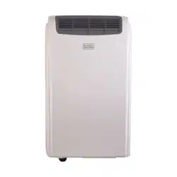
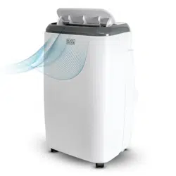
User manual Portable Air Conditioner
POWER CORD OPERATION
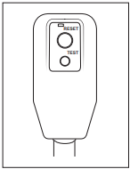
The power supply cord contains a current device that senses damage to the power cord. To test your supply cord follow these steps:
1. Plug in the Air Conditioner.
2. The power supply cord head has two buttons, a TEST button and a RESET button. Press the TEST button and notice a click as the RESET button pops out.
3. Press the RESET button. Once again notice a click as the button engages.
4. The power supply cord will now supply electricity to the unit.
NOTE:
- Do not use this device to turn the unit on or off.
- Always make sure the reset button is pushed in for correct operation
- The power supply cord must be replaced if it fails to reset when either the test button is pushed, or it cannot be reset.
- If power supply cord is damaged, it cannot be repaired.
- It must be replaced by one obtained from the product manufacturer.
- After the unit has stopped, the compressor operate for the first 3 minutes. This is to protect the unit. Operation will automatically start after 3 minutes.
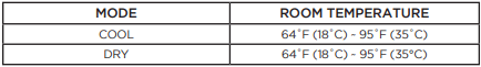
OPERATING CONDITION
The air conditioner must be operated within the temperature range indicated below:
NOTE: Unit performance may be affected when in use outside of these operating temperatures.
SET UP & USE
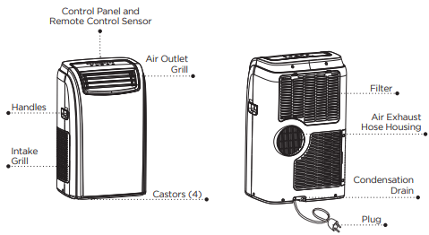
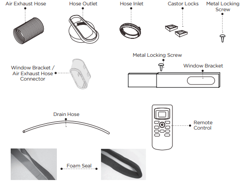
PARTS & FEATURES
SPECIFICATIONS
BPACT12 / BPACT14
- Unit Dimensions (W x D x H): 17.1” x 13.8” x 28.1”
- Unit Weight: Approx. 59.5 lbs. / 68.3 lbs.
- Electric Requirements: 115V ~ 60Hz
INSTALLATION GUIDE
LOCATION
- The air conditioner should be placed on a firm floor to minimize noise and vibration. For safe and secure positioning, place the unit on a smooth, level floor strong enough to support the unit.
- The unit has casters to aid placement, but it should be rolled on smooth, flat surfaces. Use caution when rolling on carpet surfaces. Do not attempt to roll the unit over objects.
- The unit must be placed within reach of a properly rated grounded socket.
- Never place any obstacles around the air inlet or outlet of the unit.
- Allow 12 inches to 36 inches of space from the wall with window for efficient air-conditioning.
SUGGESTED TOOLS FOR WINDOW KIT INSTALLATION
- Screwdrivers (medium size Phillips)
- Tape measure or ruler
- Knife or scissors
- Saw (In the event that the window kit needs to be cutdown in size because the window is too narrow for direct installation)
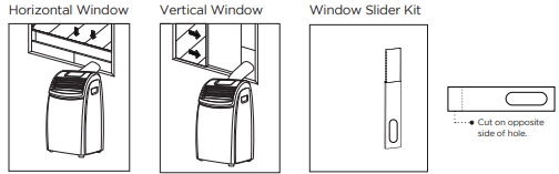
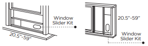
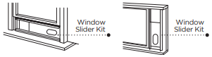
WINDOW SLIDER KIT INSTALLATION
Your window slider kit has been designed to fit most standard “Vertical” and “Horizontal” window applications; however, it may be necessary for you to improvise/modify some aspect of the installation procedures for certain types of window. Minimum and maximum window openings:
MAXIMUM: 59” (145 cm)
NOTE: A plastic locking pin is holding the window slider kit together during shipment. Prior to installation, remove plastic locking pin, adjust to desired length and use provided metal locking screws to secure.
NOTE: If the window opening is less than 20.5” the minimum length of the window slider kit, cut the one with a hole in it short to fit for the window opening. Never cut out the hole in window slider kit.
DOUBLE-HUNG SASH/SLIDING CASEMENT WINDOW INSTALLATION
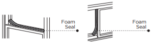
1. Cut the foam seal (adhesive type) to the proper length and attach it to the window sash.
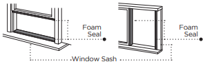
2. Attach the window slider kit to the window sash. Adjust the length of the window slider kit according to the width of window. Shorten the adjustable window kit if the width of window is less than 20.5”.
3. Cut the foam seal (adhesive type) to the proper length and attach it on the top of the window.
4. Close the window securely against the window slider kit.
5. Secure the window slider kit to the window sash.
6. Cut the foam seal to an appropriate length and seal the open gap between the top window frame and outer window frame.
EXHAUST HOSE INSTALLATION
The air exhaust hose and hose inlet must be installed or removed from the portable air conditioner in accordance with the way it is being used:
COOL, AUTO, DEHUMIDIFY: Air exhaust hose and hose inlet should be connected to the portable air conditioner.
FAN: Air exhaust hose and hose inlet should be disconnected from the portable air conditioner.
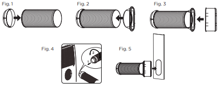
To install:
1. Connect hose inlet to one end of air exhaust hose. Push hose inlet over the end of the hose, push in slightly and then start threading it on in a counter clockwise direction. (see Fig 1)
2. Connect hose outlet to other end of air exhaust hose. Push hose outlet over the end of the hose, push in slightly and then start threading it on in a counter clockwise direction. (see Fig 2)
3. Align window bracket/air intake hose connector with hose outlet and push in until it locks into place. You will hear a clicking sound when it does. (see Fig 3)
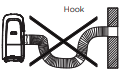
4. Place the hose inlet against the air outlet opening hook on the back of the portable air conditioner and firmly push and rotate counter clockwise to lock it into place. (see Fig 4)
5. After connecting the hose inlet to the unit, insert the window bracket/air intake hose connector into the opening of the window bracket. Align connector with the opening on the inside (side with the channels) of the window bracket and push in until it locks into place. You will hear a clicking sound when it does. (see Fig 5).
NOTE: The exhaust hose can be compressed or extended moderately, but it is desirable to keep the length to a minimum. Also make sure that the hose does not have any sharp bends.
CONTROL PANEL
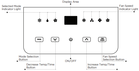
Pictures are for illustration purpose only. Your model may or may not have all the features.
OPERATING FROM THE CONTROL PANEL
The Control Panel enables you to manage all the main functions of the appliance, but to fully exploit its potential, you must use the remote control unit.

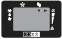
TURNING THE APPLIANCE ON
- Plug into the dedicated electrical outlet. Two lines appear on the display indicating that the appliance is in standby. (Fig. 6)
- Press the
 button until the appliance comes on. The last function active when it was turned off will appear.
- Never turn the air conditioner off by unplugging from the mains. Always press the button , then wait for a few minutes before unplugging. This allows the appliance to perform a cycle of checks to verify operation.
Note: Before pressing Power On button make sure the condensate drain plug in the rear of the unit is securely in place to avoid any leaking.
- Press the MODE button until the light corresponding to the required Mode lights up.
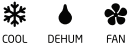
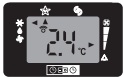
COOL MODE
Ideal for hot muggy weather when you need to cool and dehumidify the room. To set operation of the appliance correctly, press the  or
or  buttons until the desired temperature is displayed. (See Fig. 7)

Then select the fan speed by pressing the Fan Speed Button until the light corresponding to the required fan speed lights up:
HIGH: The Fan operates at maximum to reach the required temperature as rapidly as possible.
MED: Reduces Fan noise level but still maintains a good level of comfort.
LOW: For quiet operation.
AUTO: The appliance automatically selects the most suitable fan speed in relation to the temperature set on the digital display.
DEHUMIDIFYING MODE
Ideal for reducing humidity in spring and autumn, during rainy spells or in damp rooms, etc.

In dehumidifying mode, the appliance must have the same configuration as for the air conditioner mode, with the air exhaust hose fitted to the appliance to allow air to be discharged externally.
When the dehumidifying mode is selected, the light comes on and “dh” appears on the display. (See Fig. 8)
At the same time, the AUTO fan light comes on. In this mode, other fan speeds cannot be selected.
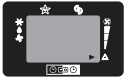
FAN MODE
Adjust fan speed by pressing the Fan Speed button as described for the cool mode.

In this mode, AUTO fan cannot be selected.
The fan speed selected will show in the display. One row for Low, Two rows for medium and three rows for high. (See fig. 9)
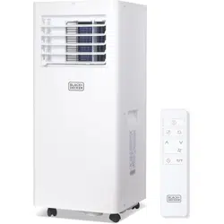
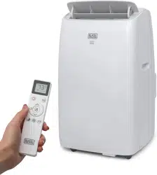
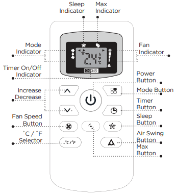
CONTROL PANEL ON REMOTE CONTROL
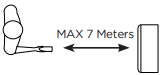
CORRECT USE
Point the remote control at the receiver on the appliance. The remote control must be no more than 7 meters away from the appliance (without obstacle between the remote control and the receiver).
The remote control must be handled with extreme care. Do not drop it or expose it to direct sun light or sources of heat.
INSERTING OR REPLACING THE BATTERIES
Removing the cover on the rear of the remote control:
Insert two R03 “AAA” 1.5V batteries in the correct position (see instructions inside the battery compartment);
Replace the cover
If the remote control unit is replaced or disposed of, the batteries must be removed and discarded in accordance with current legislation as they are harmful to the environment.
OPERATING FROM THE REMOTE CONTROL
The first part of the controls on the remote control are the same as those on the control panel of the appliance.
You should therefore refer to the instructions in the chapter Operating from the Control Panel to turn the appliance on and select the operating mode (Cool, Dry, Fan, Heat) and the fan speed.
The following section describes the additional functions corresponding to the controls on the bottom part of the remote control.
COOLING MODE
- Press the
 button to turn the appliance on.
- Press the MODE button (
 ) to select COOL.
- Set the temperature using the button.
- To select fan speed, press the FAN SPEED button repeatedly until the required speed is selected (HIGH / MED / LOW / AUTO FAN).
NOTE: In COOLING mode, the appliance automatically removes excess moisture from the atmosphere.
DEHUM MODE
- Keep the windows and doors closed for an effective dehumidification.
- When used as dehumidifier only keep the air exhaust hose disconnected.
- Press the button to turn the appliance on.
- Press the MODE button to select DRY. The fan speed will always be on FAN (Fan Speed Auto) and cannot be adjusted in DRY mode.
FAN MODE
- Press the button to turn the appliance on.
- Press the MODE button to select FAN
- To select fan speed, press the FAN SPEED button (
 ) repeatedly until the required speed is selected (HIGH / MED / LOW) and AUTO FAN SPEED can not be selected.
MAX FUNCTION
- Ideal for the summer to cool rooms rapidly.
- Activate by simply pressing the MAX button (
 ).
).
- The appliance operates in cool mode at fan speed auto. While this function is selected, it is not possible to set the temperature or change fan speed.
- Display on the control panel:
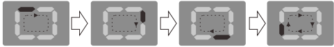
It is at max function when the display is in constant motion (see above).
SLEEP OPERATION
The selected temperature will increase (cooling) by 1˚F/1˚C for the first 60 minutes. The temperature will then increase (cooling) by another 1˚F/1˚C after an additional 60 minutes. This sleep operation will be maintained for 6 hours before it returns to shutdown.
NOTE: This feature is not available in FAN mode.
- This function is useful for the night as it gradually reduces operation of the appliance. To set this function correctly.
- Select the operating mode (COOL/DRY) as described above.
- Press the SLEEP button (
 ) the appliance operates in the previously selected mode.
AIR SWING FUNCTION
- This function is useful for selecting the left/right swing of air circulation.
- To set this function correctly:
- Select the operating mode (cool/dry/fan) as described above.
- Press the “
 ” button. The appliance operates in the previously selectced mode. The message “
 ” appears on the remote control to indicate swing is activated.
- Press the swing button again, the message “
 ” disappears to indicate swing is stopping.
SETTING THE TIMER
- This timer can be used to delay the appliance start up to shutdown, this avoids wasting electricity by optimizing operating periods.
PROGRAMMED SHUTDOWN
- With the appliance on, press the TIMER button, the TIMER is displayed under the
 .
.
- Set the time when you want the appliance to switch off using the buttons (from 30 minutes to 24 hours).
- During the first ten hours you can select half intervals. For times longer than ten hours, one hour intervals can be selected.
- Press the TIMER button again to confirm the setting. The TIMER symbol light on remote control panel will light up to indicate the timer is activated.
- At the end of the set time the appliance switches off automatically.
- To cancel the TIMER setting press the TIMER button again whenever during the set time.
PROGRAMMED START UP
- Turn on the appliance and set the working mode you desire.
- Press button to switch into STANDBY.
- Press the TIMER button twice the time is displayed and symbol.
- Set the time when you want the appliance to switch on using the buttons (from 30 minutes to 24 hours).
- During the first ten hours you can select half intervals. For times longer than ten hours, one hour intervals can be selected.
- Press the TIMER button again to confirm the setting the TIMER symbol light on control panel light up to indicate the timer is activated.
- At the end of the set time the appliance switches on automatically and operates in the same working mode as prior to switching into STANDBY, for example cooling mode, 25˚C fan speed high.
- To cancel the TIMER setting press the TIMER button again whenever during the set time.
NOTE: A flashing green dot will appear on the bottom right of control panel LCD display when timer function is active.
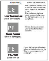
SELF-DIAGNOSIS
The appliance has a self diagnosis system to identify a number of malfunctions. Error messages are displayed on the appliance display.
WATER DRAINAGE METHOD
This air conditioner is equipped with the very latest MIST technology which means the water tank nearly never fills, hence water drainage will generally only be required at the end of the season (see START-END OF SEASON OPERATIONS in page 19. However the MIST technology does not operate when the unit is in HEAT mode. Thus the tank may still require emptying in HEAT mode.
NOTE: As a safety measure to positively prevent water spillage the air conditioner is equipped with a fail safe device if the water tank fills. The unit will completely stop, the control panel displays ft (FULL TANK) as mentioned on SELF DIAGNOSIS in page 17. The compressor and fan will not restart until the tank has been drained.
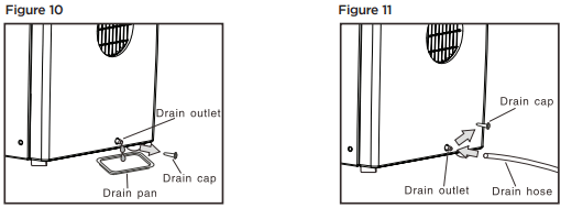
INTERMITTENT DRAINAGE (FIG. 10 AND FIG. 11)
- Turn the air conditioner off then drain the water tank by unplugging the drain cap and allowing the water to flow into a receptacle pan. Your pan may not hold the full contents of the water tank. A number of fills of your pan may be required.
- To insure all water has been removed tilt the unit by lifting it slightly upwards from the front until no more water drains from the outlet.
- Restart the air conditioner by pressing the power button. Ensure that the unit is in COOL or DRY mode. The compressor will start approximately 3 minutes after the unit is switched on.
CLEANING
Before cleaning or maintenance, turn the appliance off by pressing the button on the control panel or button on the remote control. Wait for a few minutes then unplug from the electrical outlet.
CLEANING THE CABINET
You should clean the appliance with a slightly damp cloth then dry with a dry cloth.
- Never wash the air conditioner with water. It could be dangerous/
- Never use petrol, alcohol or solvents to clean the appliance.
- Never spray insecticide liquids or similar
CLEANING THE FILTERS
To keep your air conditioner working efficiently, you should clean the filters every week of operation.
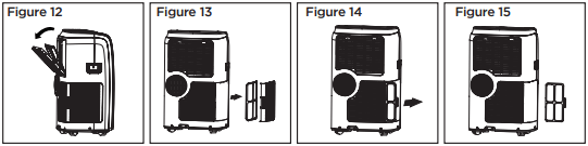
The evaporator filter can be removed as shown in Fig. 12.
The condenser filter is two pieces.
STEP 1: Take out one filter as shown in Fig. 13.
STEP 2: Take out other filter as shown in Fig. 14 and Fig. 15.
Use a vacuum cleaner to remove dust accumulations from the filters. If it is very dirty, immerse in warm water and rinse a number of times. The water should be luke warm. After washing, leave the filters to dry then re-insert.
START - END OF SEASON OPERATIONS
START OF SEASON CHECKS
Make sure the power cable and plug are undamaged. Follow the installation instructions precisely.
END OF SEASON OPERATIONS
To empty the internal circuit completely of water, remove the drain cap (Fig. 10 on page 18)
Run off all water left into basin. When all the water has been drained, put the cap back in place.
Clean the filter and dry thoroughly before putting back.
TROUBLESHOOTING & WARRANTY
BEFORE YOU CALL FOR SERVICE
Troubleshoot your problem by using the chart below. If the air conditioner still does not work properly, contact W Appliance Co. customer service center or the nearest authorized service center. Customers must never troubleshoot internal components.
Unit does not start when pressing ON/OFF button
- A. FT appears in the display window
- B. Room temperature is lower than set temperature (cooling mode)
A. Drain the water in the bottom tray
B. Reset the temperature
Not cool enough
- A. The windows or doors in the room are not closed
- B. There are heat sources inside the room
- C. Exhaust air duct is not connected or blocked
- D. Temperature setting is too high
- E. Air filter is blocked by dust
- F. The unit will take approx 3 minutes of operation before cooling/heating occurs.
A. Make sure all the windows and doors are closed
B. Remove the heat sources if possible
C. Connect the duct and make sure it can function properly
D. Decrease the set temperature
E. Clean the air filter
F. A mircoprocessor control delays the compressor from operating until 3 mins have passed.
Noisy or vibration
- A. The surface is not level or not flat enough
A. Place the unit on a flat, level surface if possible
Gurgling sound
- A. The sound comes from the flowing of the refrigerant inside the air-conditioner
A. It is normal
Unit stops operating
- A. LT appears in display window
A. Unit is in defrost mode and will restart automatically once excess frost has been removed.