Loading ...
Loading ...
Loading ...
©2012-2015 DJI. All Rights Reserved. - 14 -
Fig①A ACE
1 View Mode
1.1 View Mode Procedures
1. Check Signal Strength: shows no communication between GS and MC, please check
Troubleshooting in Appendix. is constructed, can go to next step.
2. Aircraft: When GPS signal is good enough, click Aircraft will show LATI, LONGI and ALTI of aircraft,
then the aircraft logo will be showed on the map; if the aircraft logo can’t be found, please double click
Aircraft.
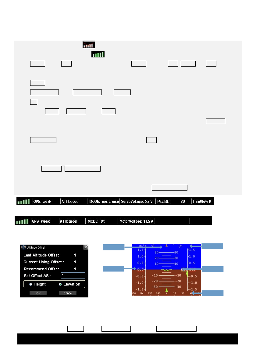
3. AltitudeOffSet: Click AltitudeOffSet from Sys_set, you can just use the value recommended, and click
OK. Read the paragraph below to get more details.
4. Switch Height or Elevation Mode: Height mode shows relative height, and the 0 meter is the aircraft
height when you choose Height mode, above 0 is positive and below 0 is negative. Elevation mode
shows height above sea level, figure is showed in Fig②
5. Home Point: Home point can be found only when GPS signal is good enough. If WKM/A2/
NAZA-M/NAZA-M V2/Phantom 2, Home Point is 20 meters above the aircraft position where user
pushes the throttle stick first time; while ACE is 30 meters.
6. View Fly Trace, Instrument Board and State Information: For displaying flight track and aircraft state.
Contents are decided by flight control system. Fig①A will be displayed if you are using ACE; Fig①B will
be displayed if WKM/A2/NAZA-M/NAZA-M V2/Phantom 2. Instrument Board is showed in Fig③.
1.2 System Setting
System Setting includes Options Setting, Altitude Offset Setting and Data Record Folder.
(1)Options
Fig③
Compass
Real-time
Vertical speed
Real-time
Altitude
Real-time
Ground speed
Real-time
Attitude
Fig①B WKM/A2/NAZA-M/NAZA-M V2/Phantom 2
Fig②
Loading ...
Loading ...
Loading ...