My O Time: Press “my o time” button and the
clock will begin flashing. Select desired o time
and press Set ( ). (Default is 10PM for all days.)
Days of the week will then flash on screen. Use
arrows ( ) to select the day(s) you want the
timer to be active and press Set ( ).
Sunset On: Press “sunset on” button and the
sunset time will flash on the screen. Use arrows
( ) to adjust time (time can be adjusted up
to 1 hour in either direction) and press Set ( ).
Days of the week will then flash on screen. Use
arrows ( ) to select the day(s) you want the
timer to be active and press Set ( ).
Sunrise O: Press “sunrise o” button and the
sunrise time will flash on the screen. Use arrows
( ) to adjust time (time can be adjusted up
to 1 hour in either direction) and press Set ( ).
Days of the week will then flash on screen. Use
arrows ( ) to select the day(s) you want the
timer to be active and press Set ( ).
Extra programs: This option oers 7 additional
On/O programs. When the “my extra programs”
button is pressed “ON 1” will flash on screen but
no time will be displayed, only “--:--.” Press Set
( ) to select program “ON 1” and the “--:--” will
flash on screen. Use arrows ( ) to select time
and press Set ( ). Days of the week will then
flash on screen. Use arrows ( ) to select the
desired days of the week and press Set ( ).
Program On 1 (“ON 1”) is now set. To go to the next program, use the arrows ( )
and press SET ( ) on the next program you want to set. Repeat these steps for
Program O 1 (“OFF 1”), Program On 2 (“ON 2”), Program O 2 (“OFF 2”), etc.
To skip through without setting, simply stop pressing buttons and the display
will revert to clock mode after 10 seconds. You can also use the arrows ( ) to
scroll through the options without setting a time. After Program O 7 (“OFF 7”),
the menu will start over with Program On 1 (“ON 1”). The LED indicator light will
remain on if any of the additional programs are set.
To delete one of the extra programs: Use arrows ( ) to choose the program
you wish to delete and press ( ) to select program. Use arrows ( ) to
scroll time back to between 11:59pm and 12:00am. The display will show “--:--”
to confirm the program has been deleted. No additional steps are needed. The
display will revert back to clock mode after 10 seconds or press Set ( ).
Note: When Program On is set to “--:--”, screen will flash “DELE” to confirm program
has been deleted.
Countdown Mode: Press “my countdown” button,
the countdown time will be flashing. Use arrows
( ) to adjust the countdown time. The switch
will now count down for the time set every time
the on/o or door override is used. While timer is in
countdown mode, the timer will run the programs
normally but will use the countdown time every
time the on/o override is selected.
4. Reset Button
To set the timer back to factory settings, press the
reset button (
r
) with a toothpick. The reset button
can be found behind the door in between the “my
extra program” and the “my countdown” buttons.
You can access the button by either removing the
door or by holding the door at a 90 degree position
and use the toothpick to depress the reset button.
1. Set Time
Use up ( ) and down ( ) arrows to set
current time. Take note of the AM/PM setting.
Note: When timer is reset, the time will flash.
2. Settings
Hold Set ( ) for 3 seconds and current time will
flash on the screen. Use ( ) to select current
time and press Set ( ).
“YEAR” will flash on the screen. Use ( ) to
select the current year and press Set ( ).
“MONT” will flash on the screen. Use ( ) to
select the current month and press Set ( ).
“DAY” will flash on the screen. Use ( ) to
select the current day and press Set ( ).
“ZONE” will flash on the screen. Use ( ) to
select current zone (see Figure 1). Zone is used
to determine sunrise/sunset times.
“DST” (Daylight Savings Time) will flash on the screen. Use ( ) to select
“ON” if you would like the timer to automatically adjust for Daylight Savings
Time or “OFF” if you would not like the timer to adjust automatically.
Note: If no button is pushed for 10 seconds, the timer will go back to clock
mode. To re-enter settings, press and hold Set ( ) for 3 seconds. Use the
( ) to scroll to the setting you were at.
Once settings are complete, either wait 10 seconds and the timer will
automatically go to clock mode, or press and hold “Set” ( ) for 3 seconds.
3. Programming Options (Preset)
Note: If the LED on a button is illuminated, this indicates that the program is
active. To deactivate program, press the button again and the LED will turn o.
Evening – Sunset to 12:AM: Press “evening”
button and the sunset time will flash on the
screen. Use arrows ( ) to adjust time (time
can be adjusted up to 1 hour in either direction)
and press Set ( ). Days of the week will flash
on the screen. Use arrows ( ) to select the
correct day options and press set ( ).
My On Time: Press “my on time” button and
the clock will begin flashing. Use arrows to set
the desired on time ( ) and press Set ( ).
(Default is 6PM for all days.) Days of the week
will then flash on screen. Use arrows ( ) to
select the day(s) you want the timer to be active
and press Set ( ).
MADE IN CHINA
Distributed by Jasco Products Company LLC, 10 E.
Memorial Rd., Oklahoma City, OK 73114.
This Jasco product comes with a 1-year limited warranty.
Visit www.byjasco.com for warranty details.
Questions? Contact us at 1-800-654-8483 between
7:00AM–8:00PM CST.
RISK OF ELECTRIC SHOCK
• SHUT OFF POWER AT FUSE BOX OR CIRCUIT
BREAKER BEFORE INSTALLATION
• DO NOT USE IN WET LOCATIONS
• USE INDOORS ONLY
RISK OF FIRE
• DO NOT USE TO CONTROL APPLIANCES
THAT CONTAIN HEATING ELEMENTS
(COOKING APPLIANCES, HEATERS,
IRONS, ETC.)
• DO NOT EXCEED ELECTRICAL RATINGS
• USE COPPER WIRE ONLY WITH THIS
DEVICE
• DO NOT USE TO CONTROL RECEPTACLES
33861-1 VERSION 01 10/27/17
Specifications:
120VAC 60Hz
15A (1800W) General Purpose/Resistive
10A (1200W) Tungsten
1200 VA Ballast
5A Electronic Ballast
1/2 HP Motor
Works with dimmable
LED and CFL bulbs.
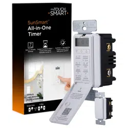
In-Wall Digital
SunSmart™
In-Wall Timer
WARNING
Patent pending
U.S. Pat 9,320,122
FCC Statement
This device complies with Part 15 of the FCC and Industry Canada license-exempt RSS standard(s). Operation is
subject to the following two conditions: (1 this device may not cause harmful interference, and (2) this device must
accept any interference received, including interference that may cause undesired operation.
FCC NOTE: The manufacturer is not responsible for any radio or TV interference caused by unauthorized
modifications to this equipment. Such modifications could void the user’s authority to operate the equipment.
NOTE: This equipment has been tested and found to comply with the limits for a Class B digital device, pursuant to
Part 15 of the FCC Rules. These limits are designed to provide reasonable protection against harmful interference in
a residential installation. This equipment generates, uses and can radiate radio frequency energy and, if not installed
and used in accordance with the instructions may cause harmful interference to radio communications. However,
there is no guarantee that interference will not occur in a particular installation. If this equipment does cause
harmful interference to radio or television reception, which can be determined by turning the equipment o and on,
the user is encouraged to try to correct the interference by one or more of the following measures:
• Reorient or relocate the receiving antenna.
• Increase the separation between the equipment and receiver.
• Connect the equipment into an outlet on a circuit dierent from that to which the receiver is connected.
• Consult the dealer or an experienced radio/TV technician for help.
CAN ICES-3(B)/NMB-3(B)
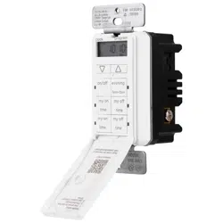
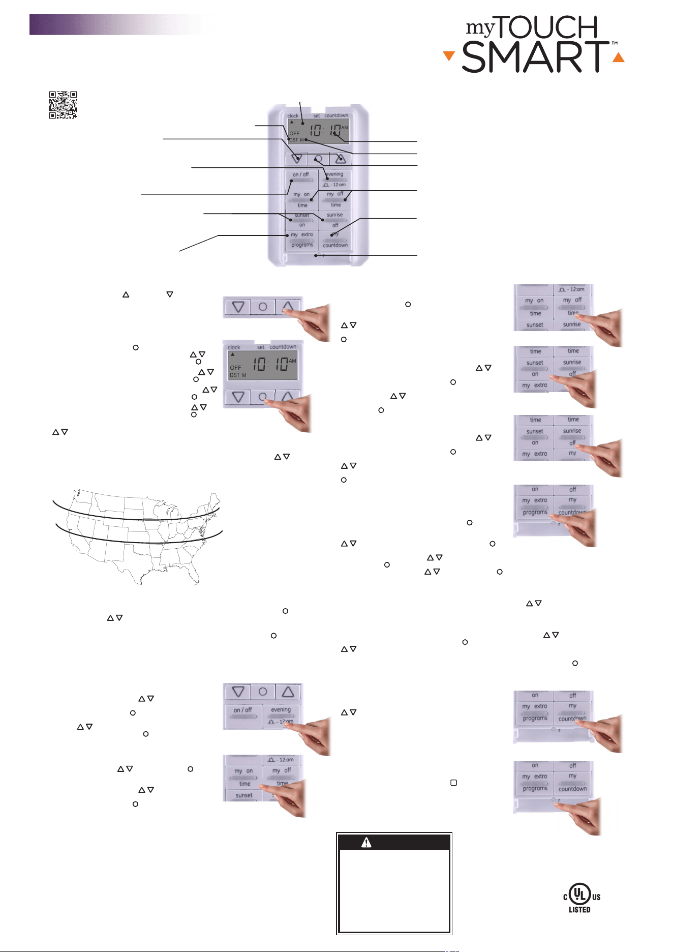
My on/o time
Set custom on/o time
Clock vs. settings indicator
Up and down arrows
Press to set current time and
schedule programs
Evening preset
Set on/o time to dusk - 12am or +/- 1hr
AM/PM indicator
Sunset on/sunrise o time
Set on/o time to sunset/sunrise or +/- 1hr
My countdown
When active, switch will
countdown every time on/o
override is activated.
Set button
Press to select various options
Day of week indicator
NORTH
ALASKA
HAWAII
NORTH
CENTRAL
CENTRAL
SOUTH
SOUTH
My extra programs button
Oers seven additional on/o programs
On/o
Overrides current program
Reset button
Press to reset
FIGURE 1
Location zones for sunrise/sunset times
Daylight savings time indicator
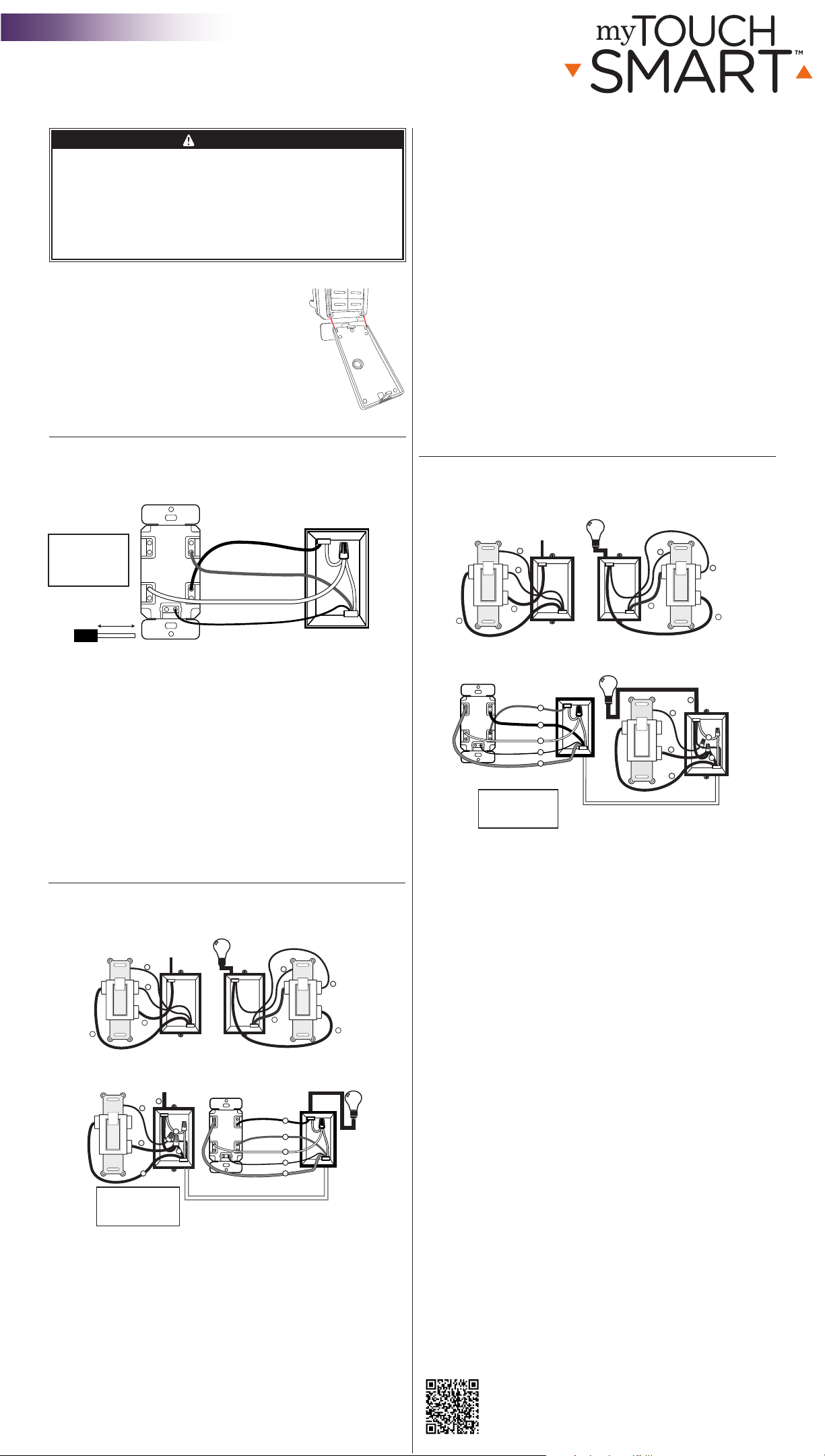
Installing the timer on the LOAD Side
1. Using the Load Side of Figure 3 as a visual reference, remove the LOAD
Side 3-way switch and the four wires, labeling the wire removed from the
common terminal as LOAD (4) and the wires from the HOT terminals (H)
as Traveler-1 (5) and Traveler-2 (7).
2. Using the Timer On LOAD Side of Figure 4 as a visual reference for the
remaining steps, connect the LOAD wire (4) to the LOAD terminal of the
timer.
3. Connect the Traveler-2 wire (7) to LINE terminal of the timer.
4. Connect the Traveler-1 wire (5) to the TRAVELER terminal of the timer.
5. Connect the white Neutral wire (2) from the switch box to the NEUTRAL
terminal of the timer. More neutral wires may be bundled in the back of
the switch box; there may be several neutral wires bound together with a
wire nut. Add the Neutral wire to the other neutral wires bound together,
ensuring the wire nut is tight. If needed use included jumper.
6. Connect the green Ground wire (3) in the switch box to the GROUND
terminal of the timer.
7. Carefully tuck the wires into the switch box, leaving room for the timer.
8. Use the supplied screws to install the timer, being careful not to crush or
pinch the wires.
9. Restore power at the circuit breaker or fuse box.
10. Verify that the LOAD turns ON/OFF when you manually turn the timer ON
and OFF. Perform this test with the remote switch in both positions. You
should hear the timer relay click ON/OFF. If you hear the relay click but the
LOAD does not turn ON/OFF properly, check your wiring.
11. If the load does not operate properly, disconnect the power at the circuit
breaker or fuse box. Then swap the Traveler-2 (Line) wire (7) and Traveler-1
wire (5) on the timer.
Timer on the LINE side 3-way installation instructions
NOTE: If you are unsure or unclear about this installation or if the wires in
your box do not match the manual (not all switch boxes have neutral wires),
contact a qualified, licensed electrician.
Preparing the switch on the LOAD side
1. Disconnect the power from the circuit by turning o the circuit breaker or
removing the fuse from the fuse box.
2. Using the Switch On LOAD Side of Figure 5 as a visual reference, label
and remove the LOAD wire (4) from the common terminal (C) and the
Traveler-2 wire (7) from the HOT terminal (H).
3. Using Figure 6 as a visual reference, connect the jumper wire (6)
(supplied), the LOAD wire (4) from the common terminal (C), and the
Traveler-2 wire (7) together. You should have three wires connected with
one wire nut. If needed use the included jumper.
4. Connect the other end of the jumper wire (6) back to the common
terminal (C) on the switch. Consider recording the marking/color coding
of the Traveler-1 (5) and Traveler-2 (7) wires so you can tell them apart for
later use.
5. Carefully tuck the wires into the switch box leaving room for the timer.
6. Install the switch back into the box.
Installing the timer on the LINE side
1. Using the LINE Side of Figure 5 as a visual reference, remove the LINE
Side 3-way switch and the four wires, labeling the wire removed from the
common terminal (C) as LINE (1) and the wires from the HOT terminals (H)
as Traveler-1 (5) and Traveler-2 (7).
2. Using the Timer on LINE Side of Figure 6 as a visual reference for the
remaining steps, connect the LINE wire (1) to the LINE terminal of the
timer.
3. Connect the white Neutral wire (2) to the NEUTRAL terminal of the timer.
More neutral wires may be bundled together in the back of the switch box;
there may be several neutral wires bound together with a wire nut. Add the
Neutral wire to the other neutral wires bound together, ensuring the wire
nut is tight.
4. Connect the Traveler-1 wire (5) to the TRAVELER terminal of the timer and
the Traveler-2 wire (7) to the LOAD terminal of the timer.
5. Connect the green Ground wire (3) to the GROUND terminal of the timer.
6. Carefully tuck the wires into the switch box, leaving room for the timer.
7. Use the supplied screws to install the timer, being careful not to crush or
pinch the wires.
8. Restore power at the circuit breaker or fuse box.
9. Verify that the LOAD turns ON/OFF when you manually turn the timer ON
and OFF. Perform this test with the remote switch in both positions. You
should hear the timer relay click ON/OFF. If you hear the relay click
but the LOAD does not turn ON/OFF properly, check your wiring.
10. If the load does not operate properly, disconnect the power at the circuit
breaker or fuse box. Then swap the Traveler-2 (LOAD) wire (7) and
Traveler-1 wire (5) at the timer or the toggle switch.
TRAVELER
LOADLINE
NEUTRAL
Typical Wiring Diagram for a 3-way installation
with timer on line side
Figure 6 - Connecting the timer wires for a 3-way
installation - timer on line side
1 = Line
2 = Neutral
3 = Ground
4 = Load
5 = Traveler-1
6 = Jumper
*7 = Traveler-2
C = Common
terminal
2
7
5
6
3
Ground
SWITCH ON LOAD SIDE
4
Load
C
Figure 5 - Typical wiring
schematic for 3-way installation
5
1
7
Hot Side
Line
LINE SIDE LOAD SIDE
C
H H
5
4
7
C
H H
Load
In a typical 3-way application there are two 3-way switches. The switch on the
“HOT” side has the common terminal tied to 120VAC. The switch on the “LOAD”
side has the common terminal tied to the load that the switches turn off and on.
Line
Neutral
Traveler-2 (Load)
Ground
Traveler-1
5
3
7
1
2
TIMER ON LINE SIDE
3
3
Ground
*Traveler-2 (7) carries Load
to the timer
H
H
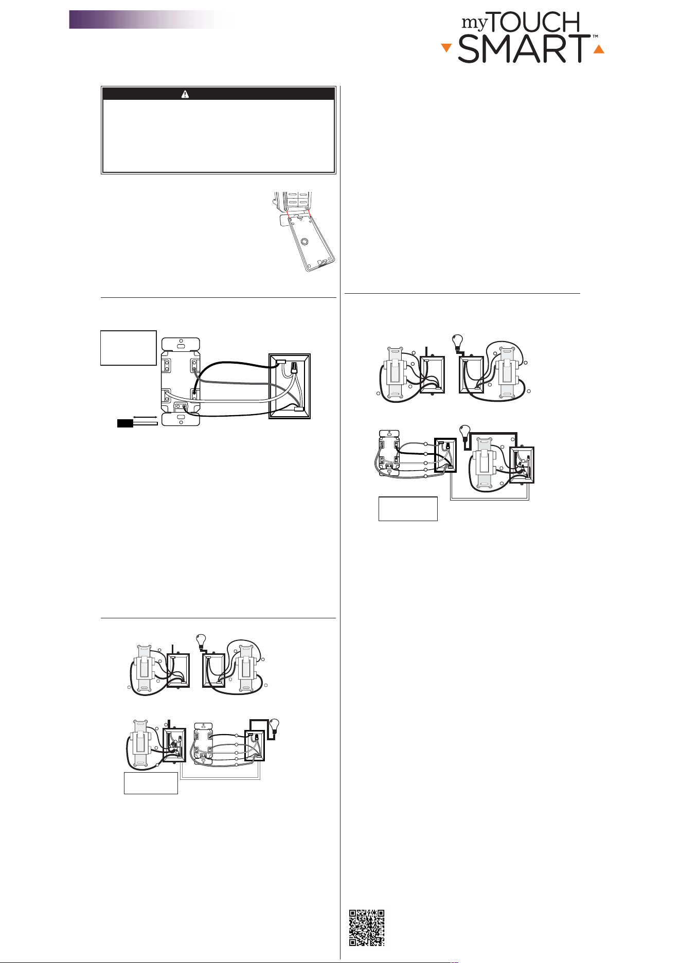
Change the door
This device includes a light almond door. To switch the
doors, proceed as follows:
1. Before installing the wall plate, or installing the timer,
open the timer door to be removed. Find the left
and right spot where the door snaps into the timer
hinges. Choose either the left or right side and pull
o the door from the timer. Once one side is pulled
o the other side will pull o easily.
2. Find the light almond door. Align the bottom of the
door with the hinges on the bottom of the timer.
Push in one of the sides of the door into the timer
hinge, it will snap into place. Snap in the second side
of the door to the timer. See Figure 1
Single-pole Installation
NOTE: If you are unsure or unclear about this installation or if the wires in
your box do not match the manual (not all switch boxes have neutral wires),
contact a qualified, licensed electrician.
Installation instructions (single-pole)
1. Turn OFF the main power at the circuit breaker or fuse box.
2. Remove the existing switch.
3. Connect the timer to the wall box wires as shown in Figure 2.
a) Connect the hot/live LINE wire to the LINE terminal of the timer.
b) Connect the hot/live LOAD wire to the LOAD terminal of the timer.
c) Connect the Ground wire to the GROUND terminal of the timer.
d) Connect the Neutral wire to the NEUTRAL terminal of the timer. Often
the Neutral wire can be found in the back of the wire box connected
with a wire nut. There may be several neutral wires bound together. Add
the timer Neutral wire to the other neutral wires, bound together making
sure the wire nut is tight. If needed use the included jumper.
4. Ensure that all terminals are tightened to between 8.85 and 12.39 lbf-in.,
and tuck the wires into the wall box, leaving room for the timer.
5. Use the screws to mount the timer to the wall box, being careful not to
crush any wires.
6. Reinstall your wallplate.
7. Turn the main power on at the circuit breaker.
8. If the timer does not turn on, disconnect the power at the circuit breaker
or fuse box. Swap the LINE and LOAD wires on the timer. Remount the
timer and wallplate, then restore power at the fuse box or circuit breaker.
Timer on LOAD side 3-way installation instructions
NOTE: If you are unsure or unclear about this installation or if the wires in
your box do not match the manual (not all switch boxes have neutral wires),
contact a qualified, licensed electrician.
Preparing the switch on the LINE Side
1. Disconnect the power from the circuit by turning o the circuit breaker
or removing the fuse from the fuse box.
2. Using the LINE Side of Figure 3 as a visual reference, label and remove
the LINE wire (1) from the common terminal (C) and the Traveler-2 wire
(7) from the HOT terminal (H).
3. Using Figure 4 as a visual reference, connect the jumper wire (6)
(supplied), the LINE wire (1) from the common terminal (C), and the
Traveler-2 wire (7) together. You should have three wires connected with
one wire nut.
4. Connect the other end of the jumper wire (6) back to the common
terminal (C) on the switch. Consider recording the marking/color coding
of the Traveler-1 (5) and Traveler-2 (7) wires so you can tell them apart
for later use.
5. Carefully tuck the wires into the box, leaving room for the switch.
6. Install the switch back into the box.
TRAVELER
LOADLINE
NEUTRAL
Figure 3 - Typical wiring
schematic for 3-way installation
2
7
5
6
1
3
Ground
C
Typical Wiring Diagram for 3-way installation
with timer on load side
Load
Line
5
1
7
3
3
Hot Side
Line
Ground
LINE SIDE
SWITCH ON LINE SIDE
LOAD SIDE
TIMER ON LOAD SIDE
C
H H
5
4
7
C
H H
Figure 4 - Connecting the timer wires for a
3-way installation - timer on load side
Load
1 = Line
2 = Neutral
3 = Ground
4 = Load
5 = Traveler-1
6 = Jumper
*7 = Traveler-2
C = Common
terminal
In a typical 3-way application there are two 3-way switches. The switch on the
“HOT” side has the common terminal tied to 120VAC. The switch on the “LOAD”
side has the common terminal tied to the load that the switches turn on and off.
Load
Neutral
Traveler-2 (Line)
Ground
Traveler-1
5
3
7
4
2
*Traveler-2 (7) carries Line to the timer
H H
TIMER
WALL BOX
Line
TRAVELER
LOADLINE
NEUTRAL
Included Neutral Jumper
Load
Ground
Figure 2 - Connecting the timer wires for single-pole installation
5/8” (1.6cm)
Wire Strip Length
WIRE
Step-by-Step
Instructional Video
RISK OF ELECTRIC SHOCK
• SHUT OFF POWER AT FUSE BOX
OR CIRCUIT BREAKER BEFORE
INSTALLATION
• DO NOT USE IN WET LOCATIONS
• USE INDOORS ONLY
RISK OF FIRE
•DO NOT USE TO CONTROL APPLIANCES THAT CONTAIN
HEATING ELEMENTS (COOKING APPLIANCES, HEATERS,
IRONS, ETC.)
• DO NOT EXCEED ELECTRICAL RATINGS
• DO NOT USE TO CONTROL RECEPTACLES
• USE COPPER WIRE ONLY WITH THIS DEVICE
• TIGHTEN ALL CONNECTIONS TO 1-1.4 N-m (8.85 TO 12.39
LBF-IN.)
• FOR SUPPLY CONNECTIONS, USE 14 AWG OR LARGER
WIRE RATED AT LEAST 75°C.
• FOR GROUNDING LEAD, USE 12 AWG OR LARGER WIRE
RATED AT LEAST 75°C.
In-Wall Digital
SunSmart™
In-Wall Timer
Line - Black
Load - Black
Neutral - White
Ground - Green
or Bare
Installation Instructions
WARNING
33861 Installation Instructions v1 12/18/17
Figure 1
Mi hora de apagado: oprima el botón “my o
time” (mi hora de apagado) y el reloj comenzará
a parpadear. Establezca la hora de apagado que
desee y oprima Set ( ). (La hora predeterminada
es 10 PM para todos los días.) Los días de la semana
comenzarán a parpadear en la pantalla. Use las flechas
( ) para seleccionar los días de la semana que
desea que el temporizador esté activo y oprima Set
( ).
Encender al anochecer: oprima el botón “sunset on”
(encender al anochecer) y el horario del anochecer
parpadeará en la pantalla. Use las flechas ( ) para
ajustar el horario (se puede ajustar hasta una hora en
cualquier dirección) y oprima Set ( ). Los días de
la semana comenzarán a parpadear en la pantalla.
Use las flechas ( ) para seleccionar los días de la
semana que desea que el temporizador esté activo y
oprima Set ( ).
Apagar al amanecer: oprima el botón “sunrise o”
(apagar al amanecer) y el horario del amanecer
parpadeará en la pantalla. Use las flechas ( ) para
ajustar el horario (se puede ajustar hasta una hora en
cualquier dirección) y oprima Set ( ). Los días de
la semana parpadearán en la pantalla. Use las flechas
( ) para seleccionar los días de la semana que
desea que el temporizador esté activo y oprima Set
( ).
Programas adicionales: esta opción ofrece 7
programas de encendido/apagado adicionales. Si
el botón “my extra programs” está presionado, “ON
1” parpadeará en la pantalla, pero no se mostrará
ningún horario, solo “--:--.” Oprima Set ( ) para
seleccionarel programa “ON 1” (ENCENDIDO 1) y
“--:--” parpadeará en la pantalla. Use las flechas
( ) para seleccionar la hora y oprima Set ( ).
Los días de la semana comenzarán a parpadear en
la pantalla. Use las flechas ( ) para seleccionar los días de la semana deseados
y oprima Set ( ). Se programó On 1 (“ENCENDIDO 1”). Para pasar al siguiente
programa, use las flechas ( ) y oprima SET ( ) en el siguiente programa que
desea configurar. Repita estos pasos para Program O 1 (“APAGADO 1”), Program On 2
(“ENCENDIDO 2”), Program O 2 (“APAGADO 2”), etc.
Para avanzar sin programar, no oprima ningún botón y la pantalla volverá al modo reloj
después de 10 segundos. También puede usar las flechas ( ) para desplazarse entre
las opciones sin programar un horario. Después de Program O 7 (“APAGADO 7”), el
menú empezará de nuevo con Program On 1 (“ENCENDIDO 1”). La luz LED permanecerá
encendida si se configuran algunos de los programas adicionales.
Para borrar uno de los programas adicionales: use las flechas ( ) para elegir el
programa que desea borrar y oprima ( ) para seleccionar el programa. Use las flechas
( ) para retroceder el horario entre las 11:59 pm y las 12:00 am. La pantalla mostrará
“--:--” para confirmar que se ha borrado el programa. No se necesitan pasos adicionales.
La pantalla volverá al modo reloj después de 10 segundos u oprima Set ( ).
Nota: cuando Program On se configura a “--:--”, en la pantalla parpadeará “DELE” para
confirmar que el programa se ha borrado.
Modo cuenta regresiva: oprima el botón “my
countdown” (mi cuenta regresiva) y la cuenta
regresiva parpadeará en la pantalla. Use las flechas
( ) para ajustar la cuenta regresiva. El dispositivo
contará de forma regresiva al horario establecido
cada vez que se use anular puertita o encendido/
apagado. Si el temporizador está en modo cuenta
regresiva, ejecutará los programas de forma normal;
pero usará la cuenta regresiva cada vez que se
seleccione anular encendido/apagado.
4. Botón de restablecer (Reset)
Para que el temporizador vuelva a su programación
de fábrica, oprima el botón Reset (
r
) con un
mondadientes. El botón Reset se encuentra detrás
de la puertita, entre los botones “my extra program”
y “my countdown”. Puede acceder a este botón al
quitar la puertita o al mantenerla a 90 grados. Use un
mondadientes para oprimir el botón Reset.
1. Programar la hora
Use las flechas arriba ( ) y abajo ( ) para
programar la hora actual. Tenga en cuenta si es AM
o PM.
Nota: al restablecer el temporizador, la hora se
encenderá en forma intermitente.
2. Programación
Oprima Set (programar) ( ) por 3 segundos y la
hora actual parpadeará en la pantalla. Use ( )
para seleccionar la hora actual y oprima Set ( ).
En la pantalla parpadeará “YEAR” (año). Use ( )
para seleccionar el año actual y oprima Set ( ).
En la pantalla parpadeará “MONTH” (mes). Use (
)
para seleccionar el mes actual y oprima Set ( ).
En la pantalla parpadeará “DAY” (día). Use ( )
para seleccionar el día actual y oprima Set ( ).
En la pantalla parpadeará “ZONE” (zona). Use
( ) para seleccionar la zona actual (ver Figura 1).
Zone (zona) se usa para determinar los horarios del
amanecer/anochecer.
“DST” (Cambio de horario de verano) parpadeará en la pantalla. Use ( ) para
seleccionar “ON” si desea que el temporizador se ajuste automáticamente al cambio
de horario de verano u “OFF” si no desea que el temporizador se ajuste de forma
automática.
Nota: si no se oprime ningún botón por el término de 10 segundos, el temporizador
volverá al modo reloj. Para volver a programar, mantenga oprimido Set ( ) por
3segundos. Use ( ) para pasar a la programación en la que estaba.
Una vez completadas las configuraciones, espere 10 segundos y el temporizador
volverá automáticamente al modo reloj o mantenga oprimido “Set” ( ) por
3segundos.
3. Programar las opciones (preprogramar)
Nota: si la luz LED de un botón está iluminada, esto indica que el programa está
activo. Para desactivar el programa, oprima el botón otra vez y la luz LED se apagará.
Anochecer hasta las 12 AM: oprima el botón “evening”
(anochecer) y la hora del anochecer parpadeará en
la pantalla. Use las flechas ( ) para ajustar el
horario (se puede ajustar hasta una hora en cualquier
dirección) y oprima Set ( ). Los días de la semana
comenzarán a parpadear en la pantalla. Use las
flechas ( ) para seleccionar las opciones de los
días correctos y oprima Set ( ).
Mi hora de encendido: oprima el botón “my on
time” (mi hora de encendido) y el reloj comenzará a
parpadear. Use las flechas para programar la hora de
encendido deseada ( ) y oprima Set ( ). (La
hora predeterminada es 6 PM para todos los días.)
Los días de la semana comenzarán a parpadear en
la pantalla. Use las flechas ( ) para seleccionar
los días de la semana que desea que el temporizador
esté activo y oprima Set ( ).
HECHO EN CHINA
Distribuido por Jasco Products Company LLC, 10 E
Memorial Rd., Oklahoma City, Oklahoma 73114.
Este producto de Jasco tiene una garantía limitada de 1 año.
Visite www.byjasco.com para conocer los detalles de la garantía.
¿Tiene preguntas? Comuníquese al 1-800-654-8483 entre las
7:00 a.m. y las 8:00 p.m. CST (hora central estándar).
RIESGO DE DESCARGA ELÉCTRICA
• INTERRUMPA EL SUMINISTRO ELÉCTRICO DESDE
EL PANEL DE FUSIBLES O EL DISYUNTOR ANTES
DE PROCEDER A LA INSTALACIÓN.
• NO UTILICE EN LUGARES HÚMEDOS
• SOLO PARA USO EN INTERIORES
RIESGO DE INCENDIO
• NO UTILICE PARA CONTROLAR APARATOS QUE
INCLUYAN RESISTENCIAS ELÉCTRICAS (APARATOS
DE COCCIÓN, CALEFACTORES, PLANCHAS, ETC.)
• NO SUPERE LOS VALORES NOMINALES
ELÉCTRICOS.
• USE SOLO CABLES DE COBRE CON ESTE
DISPOSITIVO.
• NO UTILICE EL DISPOSITIVO PARA CONTROLAR
TOMACORRIENTES
33861-1 VERSIÓN 01 10/27/17
Especificaciones:
120VAC 60Hz
15A (1800W) fines generales/carga resistiva
10A (1200W) tungsteno
1200 VA estabilizador
5A estabilizador electrónico
Motor de 1/2 HP
Funciona con bombillas atenuables
LED y CFL.
Digital de pared
SunSmart™
Temporizador de pared
ADVERTENCIA
Patente en trámite
Pat. en EE. UU. 9,320,122
Declaración de la Comisión Federal de Comunicaciones (FCC)
Este dispositivo cumple con las especificaciones del apartado15
de las normas de laFCC y con las especificaciones de las normas
radioeléctricas (RSS) del Ministerio de Industria de Canadá aplicables a aparatos exentos de licencia. El
funcionamiento está sujeto a las siguientes dos condiciones: (1) este dispositivo no debe provocar interferencia
perjudicial, y (2) este dispositivo debe aceptar toda interferencia que reciba, incluso la que pudiera causar un
funcionamiento no deseado.
NOTA DE LAFCC: El fabricante no se hace responsable de ninguna interferencia de radio oTV ocasionada por
modificaciones no autorizadas efectuadas a este aparato. Dichas modificaciones podrían anular la autoridad del
usuario para utilizar este aparato.
NOTA: este equipo ha sido probado y cumple con los límites para aparatos digitales de Clase B, de conformidad
con el apartado 15 de la normativa de la FCC. Estos límites están diseñados para proveer protección razonable
contra interferencias perjudiciales en instalaciones residenciales. Este aparato genera, usa y puede irradiar
energía de radiofrecuencias y, si no se instala y usa según las instrucciones, puede provocar interferencia
perjudicial a las radiocomunicaciones. No obstante, no hay garantías de que no ocurrirá interferencia en una
instalación en particular. Si este equipo provoca interferencia perjudicial a la recepción de radio o televisión, lo
que puede determinarse encendiendo y apagando el equipo, se recomienda que el usuario intente corregir la
interferencia por medio de la implementación de una o más de las siguientes medidas:
• Reorientar o reubicar la antena receptora.
• Incrementar la separación entre el equipo y el receptor.
• Conectar el equipo a un tomacorriente de un circuito diferente del circuito al que el receptor está conectado.
• Consultar al distribuidor o a un técnico con experiencia en radio/televisión para solicitar asistencia.
CAN ICES-3(B)/NMB-3(B)
Mi hora de encendido y apagado (on/o)
Programación personalizada de la hora de
encendido y apagado (on/o)
Indicador reloj vs. programación
Flechas arriba y abajo
Oprima para establecer la hora actual
y configurar la programación
Preprogramar para la noche
Programar hora de encender/apagar al anochecer -
las 12 AM o +/- 1h
Indicador AM/PM
Hora de encender al anochecer
y de apagar al amanecer
Programar hora de encender/apagar al
anochecer/amanecer o +/- 1h
Mi cuenta regresiva
Al activarse, el dispositivo contará de forma
regresiva cada vez que se active anular
encendido/apagado.
Botón programar
Oprimir para seleccionar varias opciones
Indicador de día de la semana
NORTE
ALASKA
HAWÁI
NORTE
CENTRAL
CENTRAL
SUR
SUR
Botón My extra programs
(Mis programas adicionales)
Ofrece siete programas adicionales de encendido/apagado
Encender/Apagar
Anula el programa actual
Botón restablecer
Oprima para restablecer
FIGURA 1
Zonas para los horarios de amanecer/anochecer
Indicador de cambio de horario de verano
Instalación del temporizador en el lado LOAD (carga)
1. Usando el lado LOAD (carga) de la Figura3 como referencia visual, quite el
interruptor de 3vías del lado LOAD (carga) y los cuatro cables. Etiquete el
cable que retiró del terminal común como LOAD (carga)(4) y cables de los
terminales vivos(H) como Terminal de retorno1(5) y Terminal de retorno2(7).
2. Usando el temporizador en el lado LOAD (carga) de la Figura4 como
referencia visual para los pasos restantes, conecte el cable LOAD (carga)(4) al
terminal LOAD (carga) del temporizador.
3. Conecte el cable de retorno2(7) al terminal LINE (línea) del temporizador.
4. Conecte el cable de retorno1(5) al terminal TRAVELER (retorno) del
temporizador.
5. Conecte el cable neutro blanco(2) de la caja de interruptores al terminal
NEUTRAL (neutro) del temporizador. Puede haber más cables neutros
amarrados en la parte trasera de la caja de interruptores con un empalme
de cable. Incluya el cable neutro a los otros cables neutros amarrados,
asegurándose de que el empalme de cable esté ajustado. De ser necesario, use
el cable del puente incluido.
6. Conecte el cable de tierra verde(3) de la caja de interruptores al terminal
GROUND (tierra) del temporizador.
7. Con cuidado, introduzca los cables en la caja de interruptores, dejando espacio
para el temporizador.
8. Utilice los tornillos provistos para instalar el temporizador, teniendo cuidado de
no apretar o pellizcar los cables.
9. Restablezca el suministro eléctrico en el disyuntor o panel de fusibles.
10. Verifique que la carga se conecte y desconecte al encender y apagar
manualmente el temporizador. Realice esta prueba con el interruptor remoto
en ambas posiciones. Debe escuchar un “clic” cuando el relé del temporizador
se enciende y apaga. Si escucha el “clic” del relé, pero la carga no se enciende
ni apaga correctamente, revise el cableado.
11. Si la carga no funciona correctamente, desconecte el suministro eléctrico en el
disyuntor o panel de fusibles. Luego, intercambie el cable de retorno2 (LINE,
línea)(7) y el cable de retorno1(5) en el temporizador.
Instrucciones de instalación de 3vías con el temporizador
en el lado LINE (línea)
NOTA: Si no está seguro o duda acerca de esta instalación, o si los cables de la
caja que usará no coinciden con el manual (no todas las cajas de interruptores
tienen cables neutros), comuníquese con un electricista calificado con licencia.
Preparación del interruptor en el lado LOAD (carga)
1. Apague el disyuntor o retire el fusible del panel de fusibles para desconectar el
suministro eléctrico del circuito.
2. Usando el interruptor en el lado LOAD (carga) de la Figura5 como referencia
visual, etiquete y quite el cable LOAD (carga)(4) del terminal común(C) y el
cable de retorno2(7) del terminal vivo(H).
3. Usando la Figura6 como referencia visual, conecte juntos el cable del
puente(6) (suministrado), el cable LOAD (carga)(4) del terminal común(C) y
el cable de retorno2(7). Debe tener tres cables conectados con un empalme
de cable. De ser necesario, use el cable del puente incluido.
4. Vuelva a conectar el otro extremo del cable del puente(6) en el terminal
común(C) del interruptor. Considere tomar nota de la codificación de
color/marcado de los cables de retorno1(5) y2(7) para poder distinguirlos
posteriormente.
5. Con cuidado, introduzca los cables en la caja de interruptores, dejando espacio
para el temporizador.
6. Vuelva a colocar el interruptor en la caja.
Instalación del temporizador en el lado LINE (línea)
1. Usando el lado LINE (línea) de la Figura5 como referencia visual, quite el
interruptor de 3vías del lado LINE (línea) y los cuatro cables. Etiquete el cable
que retiró del terminal común(C) como LINE (línea)(1) y los cables de los
terminales vivos(H) como Terminal de retorno1(5) y Terminal de retorno2(7).
2. Usando el temporizador en el lado LINE (línea) de la Figura6 como referencia
visual para los pasos restantes, conecte el cable LINE (línea)(1) al terminal LINE
(línea) del temporizador.
3. Conecte el cable neutro blanco(2) al terminal NEUTRAL (neutro) del
temporizador. Puede haber más cables neutros amarrados en la parte trasera
de la caja de interruptores con un empalme de cable. Incluya el cable neutro
a los otros cables neutros amarrados, asegurándose de que el empalme de
cable esté ajustado.
4. Conecte el cable de retorno1(5) al terminal TRAVELER (retorno) del
temporizador
y el cable de retorno2(7) al terminal LOAD (carga) del temporizador.
5. Conecte el cable de tierra verde(3) al terminal GROUND (tierra) del
temporizador.
6. Con cuidado, introduzca los cables en la caja de interruptores, dejando espacio
para el temporizador.
7. Utilice los tornillos provistos para instalar el temporizador, teniendo cuidado de
no apretar o pellizcar los cables.
8. Restablezca el suministro eléctrico en el disyuntor o panel de fusibles.
9. Verifique que la carga se conecte y desconecte al encender y apagar
manualmente el temporizador. Realice esta prueba con el interruptor remoto
en ambas posiciones. Debe escuchar un “clic” cuando el relé del temporizador
se enciende y apaga. Si escucha el “clic” del relé, pero la carga no se enciende
ni apaga correctamente, revise el cableado.
10. Si la carga no funciona correctamente, desconecte el suministro eléctrico
en el disyuntor o panel de fusibles. Luego, intercambie el cable de retorno2
(LOAD, carga)(7) y el cable de retorno1(5) en el temporizador o interruptor
basculante.
TRAVELER
LOADLINE
NEUTRAL
Diagrama de cableado típico para una instalación
de 3 vías con el temporizador en el lado LINE (línea)
Figura 6: Conexión de los cables del temporizador para una
instalación de 3 vías con el temporizador en el lado LINE (línea)
2
7
5
6
3
INTERRUPTOR EN EL LADO LOAD (carga)
4
Carga
C
Figura 5: Esquema de cableado
típico para una instalación de 3 vías
5
1
7
C
H H
5
4
7
C
H H
En una aplicación de 3 vías, existen dos interruptores de 3 vías. El interruptor del lado con
corriente (HOT) tiene el terminal común conectado a 120 V CA. El interruptor del lado “LOAD”
(carga) tiene el terminal común conectado a la carga que los interruptores desconectan y conectan.
5
3
7
1
2
TEMPORIZADOR EN EL LADO LINE (línea)
3
3
H
H
1 = Línea
2 = Neutral
3 = Conexión
4 = Carga
5 = Retorno 1
6 =
Cable del puente
*7 = Retorno 2
C = terminal
común
a tierra
Lado con corriente
Línea
Conexión
a tierra
LADO LINE (línea)
LADO LOAD (carga)
Carga
Carga
Neutral
Retorno 2 (
LOAD, carga
)
Conexión
a tierra
Retorno 1
Conexión
a tierra
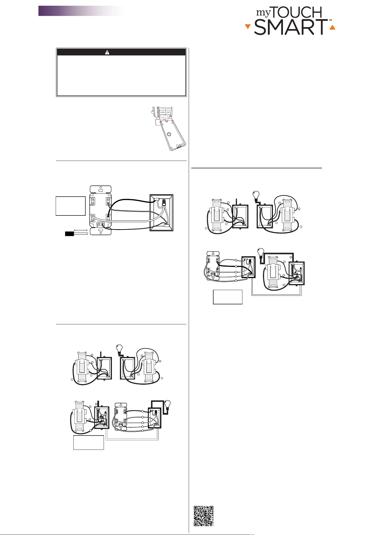
Cambiar la tapa
Este dispositivo incluye una tapa color almendra claro. Para
cambiar las tapas, haga lo siguiente:
1. Antes de instalar la placa de pared o de instalar el
temporizador, abra la tapa del temporizador que se
debe retirar. Encuentre el punto a la izquierda y a la
derecha en donde la tapa encaja en las bisagras del
temporizador. Elija el lateral izquierdo o derecho y retire
la tapa del temporizador. Una vez retirado un lateral, el
otro saldrá fácilmente.
2. Busque la tapa color almendra claro. Alinee la parte
inferior de la tapa con las bisagras de la parte inferior
del temporizador. Presione uno de los laterales de la
tapa en la bisagra del temporizador, encajará en su
lugar. Inserte el segundo lateral de la tapa en el
temporizador. Ver Figura 1.
Instalación monofásica
NOTA: Si no está seguro o duda acerca de esta instalación, o si los cables de la
caja que usará no coinciden con el manual (no todas las cajas de interruptores
tienen cables neutros), comuníquese con un electricista calificado con licencia.
Instrucciones de instalación (monofásica)
1. Interrumpa la corriente principal al disyuntor o panel de fusibles.
2. Retire el interruptor existente.
3. Conecte el temporizador a los cables de la caja de embutir, como se muestra en
la Figura2.
a) Conecte el cable vivo/con corriente LINE (línea) al terminal LINE (línea) del
temporizador.
b) Conecte el cable vivo/con corriente LOAD (carga) al terminal LOAD (carga)
del temporizador.
c) Conecte el cable GROUND (tierra) al terminal GROUND (tierra) del
temporizador.
d) Conecte el cable NEUTRAL (neutro) al terminal NEUTRAL (neutro) del
temporizador. Muchas veces, el cable neutro se puede encontrar en la parte
trasera de la caja de embutir conectado con un empalme de cable. Puede haber
varios cables neutros amarrados. Incluya el cable neutro del temporizador a los
otros cables neutros amarrados, asegurándose de que el empalme de cable esté
ajustado. De ser necesario, use el cable del puente incluido.
4. Asegúrese de que todos los terminales estén ajustados en una configuración de
entre8,85 y 12,39lbf-in e introduzca los cables en la caja de embutir, dejando
espacio para el temporizador.
5. Use los tornillos para instalar el temporizador en la caja de embutir, teniendo
cuidado de no apretar los cables.
6. Vuelva a instalar la placa de pared.
7. Restablezca la corriente principal en el disyuntor.
8. Si el temporizador no enciende, desconecte el suministro eléctrico en el
disyuntor o panel de fusibles. Intercambie los cables LINE (línea) y LOAD (carga)
en el temporizador. Vuelva a montar el temporizador y la placa de pared; luego,
restablezca el suministro eléctrico en el disyuntor o panel de fusibles.
Instrucciones de instalación de 3vías con el temporizador
en el lado LOAD (carga)
NOTA: Si no está seguro o duda acerca de esta instalación, o si los cables de la
caja que usará no coinciden con el manual (no todas las cajas de interruptores
tienen cables neutros), comuníquese con un electricista calificado con licencia.
Preparación del interruptor en el lado LINE (línea)
1. Apague el disyuntor o retire el fusible del panel de fusibles para desconectar el
suministro eléctrico del circuito.
2. Usando el lado LINE (línea) de la Figura3 como referencia visual, etiquete y
quite el cable LINE (línea)(1) del terminal común(C) y el cable de retorno2(7)
del terminal vivo(H).
3. Usando la Figura4 como referencia visual, conecte juntos el cable del puente(6)
(suministrado), el cable LINE (línea)(1) del terminal común(C) y el cable de
retorno2(7). Debe tener tres cables conectados con un empalme de cable.
4. Vuelva a conectar el otro extremo del cable del puente(6) en el terminal
común(C) del interruptor. Considere tomar nota de la codificación de color/
marcado de los cables de retorno1(5) y2(7) para poder distinguirlos
posteriormente.
5. Con cuidado, introduzca los cables en la caja de embutir, dejando espacio
para el interruptor.
6. Vuelva a colocar el interruptor en la caja.
TRAVELER
LOADLINE
NEUTRAL
Figura 3: Esquema de cableado
típico para una instalación de 3 vías
2
7
5
6
1
3
C
Diagrama de cableado típico para una instalación
de 3 vías con el temporizador en el lado LOAD (carga)
Carga
Línea
5
1
7
3
3
Lado con corriente
Línea
Conexión
a tierra
LADO LINE (línea)
INTERRUPTOR EN EL LADO LINE (línea)
LADO LOAD (carga)
TEMPORIZADOR EN EL LADO LOAD (carga)
C
H H
5
4
7
C
H H
Figura 4: Conexión de los cables del temporizador para una
instalación de 3 vías con el temporizador en el lado LOAD (carga)
Carga
1 = Línea
2 = Neutral
3 = Conexión
4 = Carga
5 = Retorno 1
6 =
Cable del puente
*7 = Retorno 2
C = terminal
común
En una aplicación de 3 vías, existen dos interruptores de 3 vías. El interruptor del lado con
corriente (HOT) tiene el terminal común conectado a 120 V CA. El interruptor del lado “LOAD”
(carga) tiene el terminal común conectado a la carga que los interruptores conectan y desconectan.
Carga
Neutral
Retorno 2 (LINE, línea)
Conexión
a tierra
Retorno 1
5
3
7
4
2
*El retorno 2 (7) transporta la línea al temporizador.
H H
Conexión
a tierra
a tierra
TEMPORIZADOR
CAJA DE EMBUTIR
Línea
RETORNO
CARGALÍNEA
NEUTRAL
Cable del puente
neutro incluido
Carga
Conexión a tierra
Figura 2: Conexión de los cables del temporizador para una instalación monofásica
5/8” (1,6 cm)
Largo de pelado
del cable
CABLE
Video instructivo
paso a paso
RIESGO DE DESCARGA ELÉCTRICA
• INTERRUMPA EL SUMINISTRO ELÉCTRICO
DESDE EL PANEL DE FUSIBLES O EL
DISYUNTOR ANTES DE PROCEDER CON LA
INSTALACIÓN.
• NO UTILICE EL DISPOSITIVO EN
LUGARES HÚMEDOS.
• SOLO PARA USO EN INTERIORES.
ADVERTENCIA
RIESGO DE INCENDIO
NO UTILICE EL DISPOSITIVO PARA CONTROLAR APARATOS QUE
INCLUYAN RESISTENCIAS ELÉCTRICAS (APARATOS DE COCCIÓN,
CALEFACTORES, PLANCHAS,ETC.).
• NO SUPERE LOS VALORES NOMINALES ELÉCTRICOS.
• NO UTILICE EL DISPOSITIVO PARA CONTROLAR TOMACORRIENTES.
• USE SOLO ALAMBRE DE COBRE CON ESTE DISPOSITIVO.
• APRIETE TODAS LAS CONEXIONES A 1-1,4N-m (DE8,85 A 12,39LBF-IN).
• PARA LAS CONEXIONES DE SUMINISTRO, USE UN CABLE DE 14AWG O
UN CALIBRE SUPERIOR APTO, COMO MÍNIMO, PARA 75°C.
• PARA LA CONEXIÓN A TIERRA, USE UN CABLE DE 12AWG O UN
CALIBRE SUPERIOR APTO, COMO MÍNIMO, PARA 75°C.
Digital de pared
SunSmart™
Temporizador de pared
Instrucciones de instalación
Línea - Negro
Carga - Negro
Neutral - Blanco
Tierra - Verde
o Desnudo
Figura 1