Loading ...
Loading ...
Loading ...
88 Outside Unit
Variable Water Flow Control KIT(Accessory)
Variable Water Flow Control KIT(Accessory)
1. Shut off the main power line of outdoor unit.
2. Install the VWFC(Variable Water Flow Control) PCB in the C/BOX by using screws.
3. Install the transformer in the C/BOX by using screws.
4. Install the terminal block in the C/BOX by using screws.
5. Connect the Main PCB(CN41) to VWFC(CN_OUT) by using the cable assy.
6. Connect the blue wire of transformer to the Main PCB (JIG1(L), JIG2(N)).
7. Connect the red wire of transformer to the terminal block (2Pin Yellow terminal block).
8. Connect a power cable (DC 12V) to CN_PWR(12V, GND) of VWFC.
9. Connect a signal cable (DC 0~10V) of water flow control valve to CN_AO(AO_01(A+), GND(A-)) of VWFC.
10. Case of two water flow control valve, Connect a signal cable (DC 0~10V) of water flow control valve to
CN_AO(AO_02(B+), GND(B-)) of VWFC.
11. Connect a power cable (AC 24V) of water flow control valve to the terminal block (2Pin Yellow terminal block, Max cur-
rent 0.42A).
12. Connect the RS-485 communication cable to CN_COMM(BUS_A, BUS_B) of VWFC
13. Set up the main function Dip S/W of VWFC PCB.
14. Set up the Dip SW of outdoor main PCB.
15. Turn on the main power line of outdoor unit.
16. Check the signal of water flow control valve to CN_AO(AO_01, GND) of VWFC and the water flow rate.
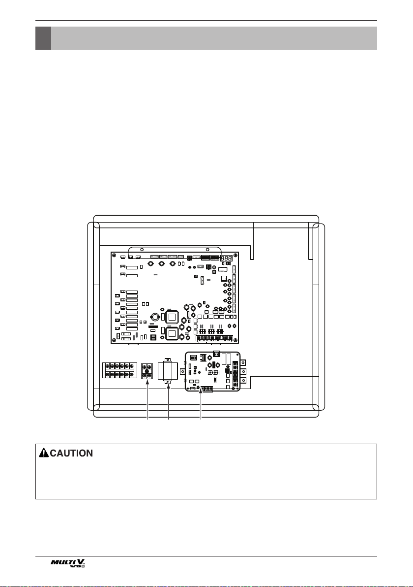
1 2 3
1: Terminal block
2 : Transformer
3 : VWFC PCB
1. Install the product on flat surface and screw at least 2 places. Otherwise the VWFC PCB may not be anchored properly.
2. Do not deform the case at random. It may cause malfunction of the Variable Water Flow Control PCB
3. This is a class A product. In a non-industrial environment, this product may cause radio interference, in which case the user
may be required to take adequate measures.
Loading ...