Loading ...
Loading ...
Loading ...
ENGLISH
Installation Manual 79
Test Run
Self-Diagnosis Function
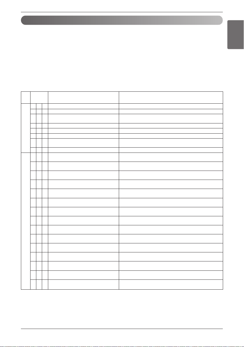
Error Indicator
• This function indicates types of failure in self-diagnosis and occurrence of failure for air condition.
• Error mark is displayed on display window of indoor units and wired remote controller, and 7-segment LEDof
outside unit control board as shown in the table.
• If more than two troubles occur simultaneously, lower number of error code is first displayed.
• After error occurrence, if error is released, error LED is also released simultaneously.
Error Display
1st,2nd LED of 7-segment indicates error number, 3rd LED indicates unit number.
Ex) 211 : No.21 error of master unit
213 : No.21 error of slave2
011 ’ 051 : No.105 error of master unit
Air temperature sensor of indoor unit is open or short
Inlet pipe temperature sensor of indoor unit is open or short
Failing to receive wired remote controller signal in indoor unit PCB
Malfunction of drain pump
Failing to receive outside unit signal in indoor unit PCB
Outlet pipe temperature sensor of indoor unit is open or short
In case when the serial number marked on EEPROM of Indoor unit is
0 or FFFFFF
Disconnecting the fan motor connector/Failure of indoor fan motor lock
Master outside unit Variable speed compressor drive IPM error
Slave1 outside unit Variable speed compressor drive IPM error
Slave2 outside unit Variable speed compressor drive IPM error
Master Outdoor Unit Inverter Board Input Current excess (RMS)
Slave2 Outdoor Unit Inverter Board Input Current excess (RMS)
Slave2 outside unit Variable speed compressor drive IPM error
DC voltage is not charged after master outside unit operating relay is
turned on
DC voltage is not charged after slave1 outside unit operating relay is
turned on
DC voltage is not charged after slave2 outside unit operating relay is
turned on
Compressor maintenance by master outside unit high pressure switch
Flow rate insufficiency or flow switch trouble of master outside unit
Compressor maintenance by slave1 outside unit high pressure switch
Flow rate insufficiency or flow switch trouble of slave1 outside unit
Compressor maintenance by slave2 outside unit high pressure switch
Flow rate insufficiency or flow switch trouble of slave2 outside unit
Master outside unit input voltage of 290V or above or 173V or less
Slave1 outside unit input voltage of 290V or above or 173V or less
Slave2 outside unit input voltage of 290V or above or 173V or less
0 1 - Air temperature sensor of indoor unit
0 2 - Inlet pipe temperature sensor of indoor unit
03-
Transmission error : wired remote controller ÷
indoor unit
0 4 - Drain pump
0 5 - Transmission error : outside unit ÷ indoor unit
0 6 - Outlet pipe temperature sensor of indoor unit
0 9 - Indoor EEPROM Error
1 0 - Poor fan motor operation
211
Master outside unit Variable speed compressor
IPM fault
212
Slave1 outside unit Variable speed compressor
IPM fault
2 1 3 Slave2 outside unit Variable speed compressor
IPM fault
221
Master Inverter Board Input Over
Current(RMS) of Master Outdoor Unit
222
Slave1 Inverter Board Input Over
Current(RMS) of Master Outdoor Unit
223
Slave2 Inverter Board Input Over
Current(RMS) of Master Outdoor Unit
231
Master outside unit Variable speed compressor
DC link under-voltage
232
Slave1 outside unit Variable speed compressor
DC link under-voltage
233
Slave2 outside unit Variable speed compressor
DC link under-voltage
2 4 1 Master outside unit high pressure switch
2 4 2 Slave1 outside unit high pressure switch
2 4 3 Slave2 outside unit high pressure switch
251
Master outside unit input voltage over-volt-
age/under-voltage
252
Slave1 outside unit input voltage over-volt-
age/under-voltage
253
Slave2 outside unit input voltage over-volt-
age/under-voltage
Display
Error item Root cause of error
number
Indoor unitOutside unit
Loading ...
Loading ...
Loading ...