Loading ...
Loading ...
Loading ...
Device protection unit
32 Outside Unit
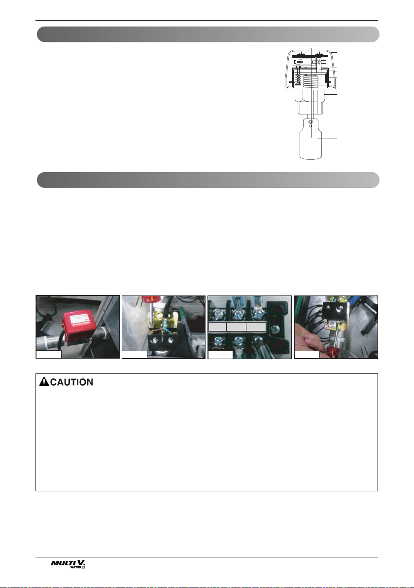
Installation of flow switch
• The flow switch must be installed at the horizontal pipe of the heat water supply outlet of the product and check the direc-
tion of the heat water flow before the installation. (Picture 1)
• When connecting the flow switch to the product, remove the jump wire to connect to the communication terminal (4(A) and
4(B)) of the outside unit control box. (Picture 2, 3) (Open the cover of the flow switch and check the wiring diagram before
connecting the wires. The wiring method can differ by the manufacturer of the flow switch.)
• If necessary, adjust the flow rate detection screw after consulting with an expert and adjust to the minimum flow rate
range. (Picture 4) (Minimum flow rate range of this product is 50%. Adjust the flow switch to touch the contact point when
the flow rate reaches 50% of the flow rate.)
- Reference flow rate : 8HP – 21 GPM, 16HP – 42 GPM
10HP – 25 GPM, 20HP – 50 GPM
Picture 1
Picture 4
Picture 3
3(B) 4(A) 4(B)
Picture 2
Flow switch work
• It is recommended to install the flow switch to the water collection pipe system
connecting to the outside unit.
(Flow switch acts as the 1st protection device when the heat water is not sup-
plied. If a certain level of water does not flow after installing the flow switch, an
error sign of CH24 error will be displayed on the product and the product will stop
operating.)
• When setting the flow switch, it is recommended to use the product with default
set value to satisfy the minimum flow rate of this product. (The minimum flow rate
range of this product is 50%. Reference flow rate : 8HP - 80LPM, 16HP -
155LPM)
• Select the flow switch with the permitted pressure specification considering the
pressure specification of the heat water supply system. (Control signal from out-
side unit is AC 220V.)
1 inch or
3/4 inch
socket
Cover
Micro-switch
Adjustment screw
Vibration plate
Bellows
Pad
• If the set value does not satisfy the minimum flow rate or if the set value is changed by the user arbitrarily, it can result
in product performance deterioration or serious product problem.
• If the product is operated with the heat water supply not flowing smoothly, it can damage the heat exchanger or cause
serious product problems.
• In case of CH24 or CH180 error, there is a possibility that the plate type heat exchanger is partially frozen inside. In this
case resolve the issue of partial freezing and then operate the product again. (Cause of partial freezing : Insufficient
heat water flow rate, water not supplied, insufficient coolant, alien particle penetrated inside plate type heat exchanger)
• When the product operates while the flow switch touches the contact point at the flow rate range out of the permitted
range, it can cause product performance deterioration or serious product problem.
• Must use the normal closed type flow switch - Circuit of outside unit is normal closed type
Loading ...
Loading ...
Loading ...