Loading ...
Loading ...
Loading ...
ENGLISH
Installation Manual 69
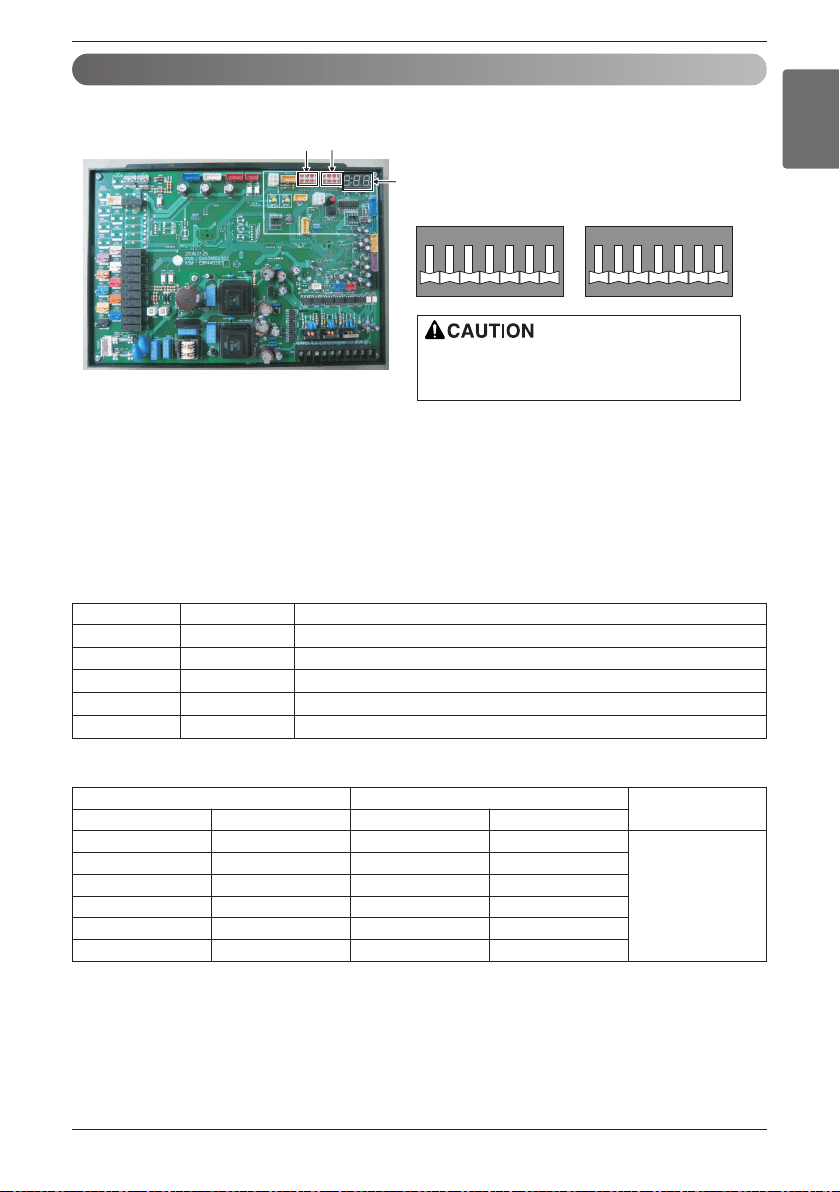
HR Unit PCB
Dip switch setting
1. Location of setting switch
2. Dip switch setting
1) Set the dip switch and turn on the power of the outside unit to check whether the set value is correctly
entered in the 7 segment.
2) This function is shown for only 2 seconds after the power is connected.
n Check outside unit setting
• The number on the 7 segment is displayed in order after the power is connected.
• This number represents the setting condition.
n Mode code
If the applicable dip switch is not set correctly,
the product may not operate properly.
SW01B
SW02B
7 segment
SW01B
1234567
ON
SW02B
1234567
ON
Order Number Item
1 - Model code
2 - Total capacity(HP)
3 2 Heat pump model
4 25 Normal mode display (If the dip switch is set incorrectly, it is not displayed.)
5 132 Model type (Heat recovery)
220V 460V
Refrigerant
Model Code Capacity (HP) Model Code Capacity (HP)
146 8 148 10
R410A
147 16 149 20
147, 146 24 149, 148 30
147, 147 32 149, 149 40
147, 147, 146 40 149, 149, 148 50
147, 147, 147 48 149, 149, 149 60
Loading ...
Loading ...
Loading ...