Loading ...
Loading ...
Loading ...
18
<ARE1349> En
E
E
NGLISH
NGLISH
○○○○○○○○○○○○○○○○○○○○○○○○○○○○○○○○○○○○○○○○○○○○○○○○○○○○○○○○○○○○○○
SETTING U
P THE SYSTEM
○○○○○○○○○○○○○○○○○○○○○○○○○○○○○○○○○○○○○○○○○○○○○○○○○○○○○○○○○○○○○○○○○○○○○○○○○○○○○○○○○○○
SETTING UP THE SYSTEM
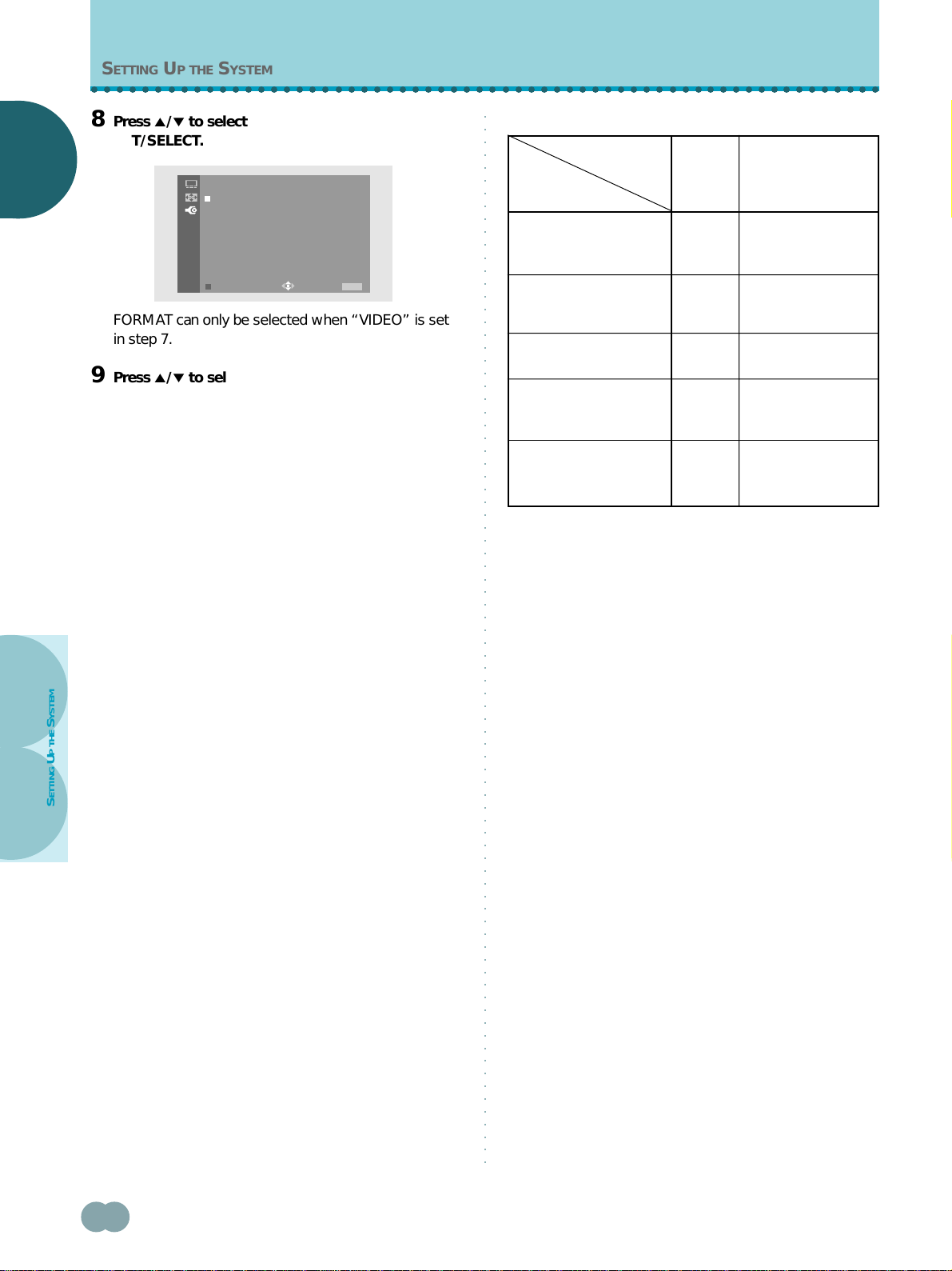
8 Press 5/∞ to select FORMAT, then press
SET/SELECT.
FORMAT can only be selected when “VIDEO” is set
in step 7.
9 Press 5/∞ to select the input signal format.
The table in the right column on this page shows what
settings are appropriate and available for the type of
connections made.
After selecting, press SET/SELECT to enter your
selection.
10When the setup is completed, press MENU to exit
the menu screen.
Notes
÷ Make this setup for each input (INPUT3 and INPUT4).
÷ When selecting a PC signal or when SIGNAL is set to “PC”,
FORMAT cannot be selected.
÷ When FORMAT is set to “COMPONENT” (1 or 2), “G ON
SYNC” cannot be set.
÷ Please refer to page 19 for details concerning G ON SYNC
setup.
* Select either COMPONENT 1 or 2 depending on which setting
provides the most natural picture color for the component
connected.
Note
When a DTV Set Top Box is connected, please also refer to
“About DTV Set Top Box connection” on page 14.
Set SIGNAL and FORMAT as follows.
Component video output
of a DTV Set Top Box with
HDTV output
Component video output
of a DVD player, etc.
RGB video output of a
video deck etc., with RGB
output
Connected
component
FORMATSIGNAL
SET UP
PC
VIDEO
VIDEO
VIDEO COMPONENT 1*
RGB (Fixed to RGB
when SIGNAL is set
to “PC”.)
RGB
COMPONENT 2*
RGB video output of a PC
Component video output
of a DTV Set Top Box with
SDTV output
VIDEO COMPONENT 2*
SET UP
FORMAT:COMPONENT1
COMPONENT2
RGB
EXIT
USE:
END: MENU
Loading ...
Loading ...
Loading ...