Loading ...
Loading ...
Loading ...
10
<ARE1349> En
E
E
NGLISH
NGLISH
○○○○○○○○○○○○○○○○○○○○○○○○○○○○○○○○○○○○○○○○○○○○○○○○○○○○○○○○○○○○○○
INSTALLATION
AND CONNECTIONS
○○○○○○○○○○○○○○○○○○○○○○○○○○○○○○○○○○○○○○○○○○○○○○○○○○○○○○○○○○○○○○○○○○○○○○○○○○○○○○○○○○○
INSTALLATION AND CONNECTIONS
○○○○○○○○○○○○○○○○○○○
About the input jacks on this unit
Connect the output jacks of components to the input
jacks of this unit following the list below (pages 10 to 14).
*1 Although INPUT3 and INPUT4 are compatible with various
kinds of signals, setup using the on-screen menu is
necessary after connections are made in order match the
characteristics of the source component (pages 17 to 19).
*2 INPUT4 is compatible with Microsoft’s Plug & Play (VESA
DDC 1/2B). INPUT3 is not compatible with this.
*3 Depending on the video output board of the computer, this
type of connection may not be possible.
○○○○○○○○○○○○○○○○○○○
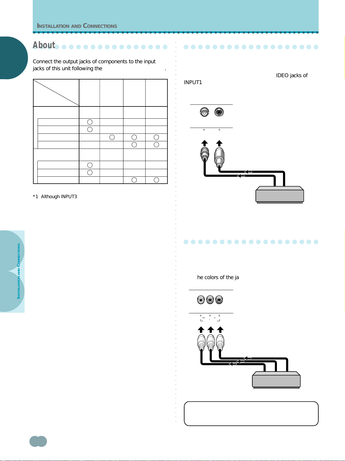
Connection to INPUT1
Connect an AV component that has a video or S-video
output jack to the INPUT1 jacks on the main unit. It is
possible to use both the VIDEO and S-VIDEO jacks of
INPUT1 at the same time for the connection. However, if
simultaneous signals are received, the S-video signal is
given priority.
If necessary, use the Pin/BNC conversion adapter to
make connections.
○○○○○○○○○○○○○○○○○○○
Connection to INPUT2
Connect an AV component that has component video
output jacks to the C-VIDEO input jacks on this unit. Be
sure to match the colors of the component cable plugs
with the colors of the jacks on both components.
For the screen sizes and input signals that INPUT1 and
INPUT2 are compatible with, please refer to
supplement 1 (page 55).
Input of
this unit
INPUT1 INPUT2 INPUT4
*1
INPUT3
*1
Composite video
Personal computer
(PC)
AV component
Connected
component
and signals
*2
S video
Component video
RGB
Composite video
S video
RGB
AV component
AV component
*3
*3
S-VIDEOVIDEO
INPUT1
INPUT2
C
B
/P
B
C
R
/P
R
C-VIDEO
Y
Loading ...
Loading ...
Loading ...