Loading ...
Loading ...
Loading ...
INSTALLATION
AND CONNECTIONS
○○○○○○○○○○○○○○○○○○○○○○○○○○○○○○○○○○○○○○○○○○○○○○○○○○○○○○○○○○○○○○
E
E
NGLISH
NGLISH
○○○○○○○○○○○○○○○○○○○○○○○○○○○○○○○○○○○○○○○○○○○○○○○○○○○○○○○○○○○○○○○○○○○○○○○○○○○○○○○○○○○
<ARE1349> En
11
○○○○○○○○○○○○○○○○○○○
Connection to INPUT3 and INPUT4
Various components can be connected to the INPUT3 and
INPUT4 jacks. After connections are made, on-screen
setup is necessary to match the characteristics of the
connected component. Please see pages 17 to 19 for
on-screen setup after connection.
Note
Components compatible with INPUT3 are also compatible with
INPUT 4.
When making connections to INPUT4, please refer to
supplement 3 on page 57.
For the screen sizes and input signals that
INPUT3 and INPUT4 are compatible with, please
refer to supplements 1 and 2 (pages 55 and 56).
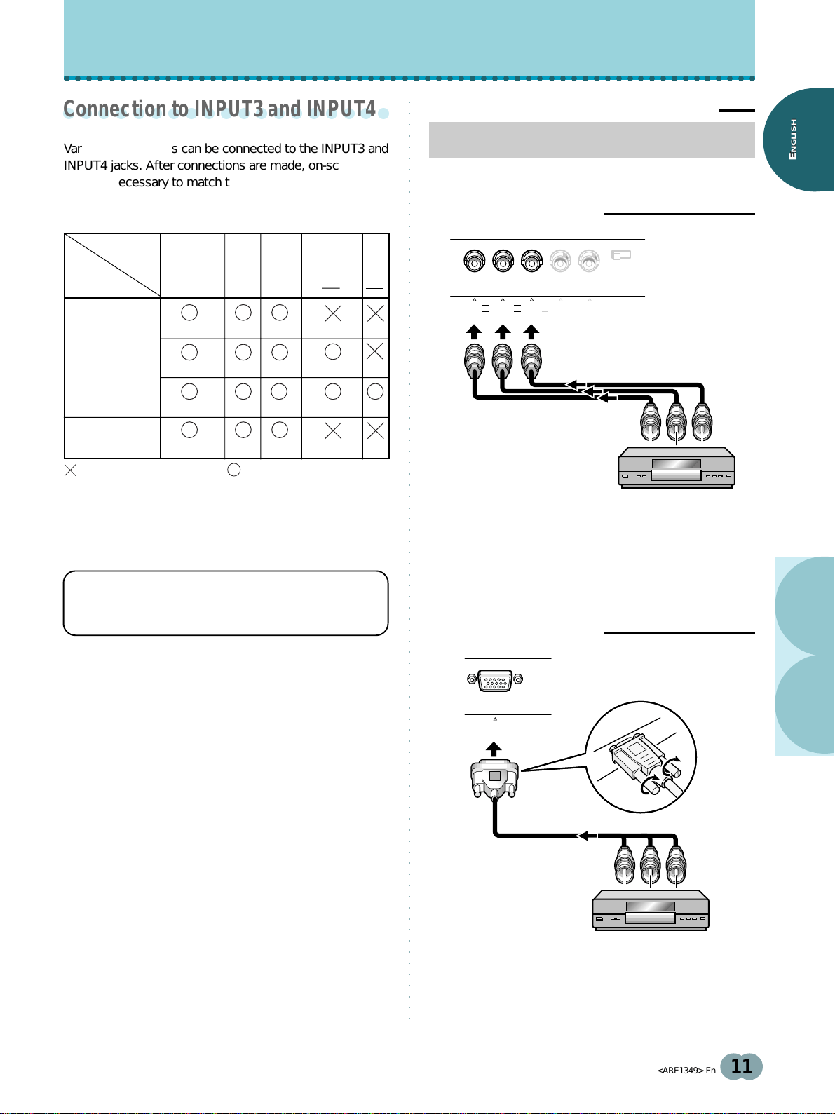
Connection to AV components
Connection to AV component that has
component video jacks
Make component video connections for AV components
with component video output capability.
When connecting to INPUT3
On-screen setup is necessary after connection.
Please see pages 17 and 18.
INPUT3 jacks are all BNC jacks.
If necessary, use Pin/BNC conversion adapters to make
connections.
When connecting to INPUT4
On-screen setup is necessary after connection.
Please see pages 17 and 18.
INPUT3
jack
Output source
[ON SYNC]
GBR
[H/V SYNC]
HD VD
Video component/
personal
computer (PC)
with RGB output
Video component
with component
video output
G ON SYNC
R
RG
G
Y
B
(C
B
/P
B
)
R
(C
R
/P
R
)
B
B
VD
H/V SYNC
HD
INSTALLATION AND CONNECTIONS
Y
CB/PB CR/PR
: Do not connect anything. : Connect to this jack.
G B R HD VD
75Ωj2.2kΩ
Y C
B
/P
B
INPUT3(ON SYNC) (H/V SYNC)
C
R
/P
R
ANALOG
R G B
INPUT4
Loading ...
Loading ...
Loading ...