Home
Bookmarks
Home
Binder
Binder M 400 User Manual
Page 61
Binder M 400
User Manual - Page 61
For M 400.
PDF File Manual
,
71 pages
,
Read Online
|
Download pdf file
More photos
1. Safety
1.1 Legal considerations
1.2 Structure of the safety instructions
1.2.1 Signal word panel
1.2.2 Safety alert symbol
1.2.3 Pictograms
1.2.4 Word message panel structure
1.3 Localization / position of safety labels on the chamber
1.4 Type plate
1.5 General safety instructions on installing and operating the chambers
1.6 Intended use
2. Chamber description
2.1 Chamber overview
2.2 Control panel
3. Completeness of delivery, transportation, storage, and installation
3.1 Unpacking, and checking equipment and completeness of delivery
3.2 Guidelines for safe lifting and transportation
3.3 Storage
3.4 Location of installation and ambient conditions
4. Installation and connections
4.1 Electrical connection
4.2 Connection to a suction plant (optional)
5. Start up
5.1 Function overview of the MB1 display program controller
5.2 Operating modes
5.3 Performance after power failures
5.4 Turning on the chamber
6. Controller MB1 settings
6.1 Selection of the menu language
6.2 Overview of program controller MB1 displays
6.3 Menu settings in the âUser-settingsâ menu
6.4 Menu settings in the âUser Levelâ menu
7. Graphic representation of the historical measurement (chart recorder function)
7.1 Setting the storage rate
8. Manual Mode
8.1 Entering the set point values
8.2 Performance after power failure in Manual Mode
9. Program operation
9.1 Menu-based program entry
9.2 Selecting between set-point ramp and set-point step
9.3 Program entry as set-point ramp or as set-point step
9.4 Information on programming different temperature transitions
9.5 Repetition of a section or several sections within a program
9.6 Performance after power failure in Program Mode
9.7 Starting a previously entered program
9.8 Deleting a program
9.9 Temperature profile template
9.10 Program table template
10. Temperature safety devices
10.1 Temperature safety device class 2 (DIN 12880)
10.2 Temperature safety device class 3.1 (DIN 12880) (available via BINDER INDIVIDUAL customized solutions)
11. Options
11.1 APT-COM⢠4 Multi Management Software (option)
11.2 Ethernet interface
11.3 HEPA fresh air filter (option)
11.4 Data logger kit (option)
11.5 Additional flexible Pt100-temperature sensor (option)
11.6 Analog output for temperature (option)
11.7 Additional measuring channel for digital object temperature indicator with flexible temperature sensor Pt 100 (option)
11.8 Mostly gas-tight version (option for M 53 and M 115)
11.9 Inert gas connection with mostly gas-tight version (option for M 53 and M 115)
11.10 Keyboard locking (option)
12. Maintenance, cleaning, and service
12.1 Maintenance intervals, service
12.2 Cleaning and decontamination
12.2.1 Cleaning
12.2.2 Decontamination
12.3 Sending the chamber back to BINDER GmbH
13. Disposal
13.1 Disposal of the transport packing
13.2 Decommissioning
13.3 Disposal of the chamber in the Federal Republic of Germany
13.4 Disposal of the chamber in the member states of the EU except for the Federal Republic of Germany
13.5 Disposal of the chamber in non-member states of the EU
14. Troubleshooting
15. Technical description
15.1 Factory calibration and adjustment
15.2 Definition of usable volume
15.3 Over current protection
15.4 Technical data
15.5 Equipment and options (extract)
15.6 Accessories and spare parts (extract)
15.7 Dimensions M 53
15.8 Dimensions M 115
15.9 Dimensions M 240
15.10 Dimensions M 400
15.11 Dimensions M 720
16. EU Declaration of Conformity
17. Product registration
18. Contamination clearance certificate
18.1 For chambers located outside the USA and Canada
18.2 For chambers located in the USA and Canada
Page 61/71
Page 1
Page 2
Page 3
Page 4
Page 5
Page 6
Page 7
Page 8
Page 9
Page 10
Page 11
Page 12
Page 13
Page 14
Page 15
Page 16
Page 17
Page 18
Page 19
Page 20
Page 21
Page 22
Page 23
Page 24
Page 25
Page 26
Page 27
Page 28
Page 29
Page 30
Page 31
Page 32
Page 33
Page 34
Page 35
Page 36
Page 37
Page 38
Page 39
Page 40
Page 41
Page 42
Page 43
Page 44
Page 45
Page 46
Page 47
Page 48
Page 49
Page 50
Page 51
Page 52
Page 53
Page 54
Page 55
Page 56
Page 57
Page 58
Page 59
Page 60
Page 61
Page 62
Page 63
Page 64
Page 65
Page 66
Page 67
Page 68
Page 69
Page 70
Page 71
Contents
Table of Contents
Search
Previous
Next
Troubleshooting
Bookmarks
Loading ...
Loading ...
Loading ...
M (E2)
04
/201
9
page
61
/
71
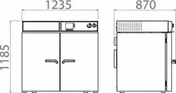
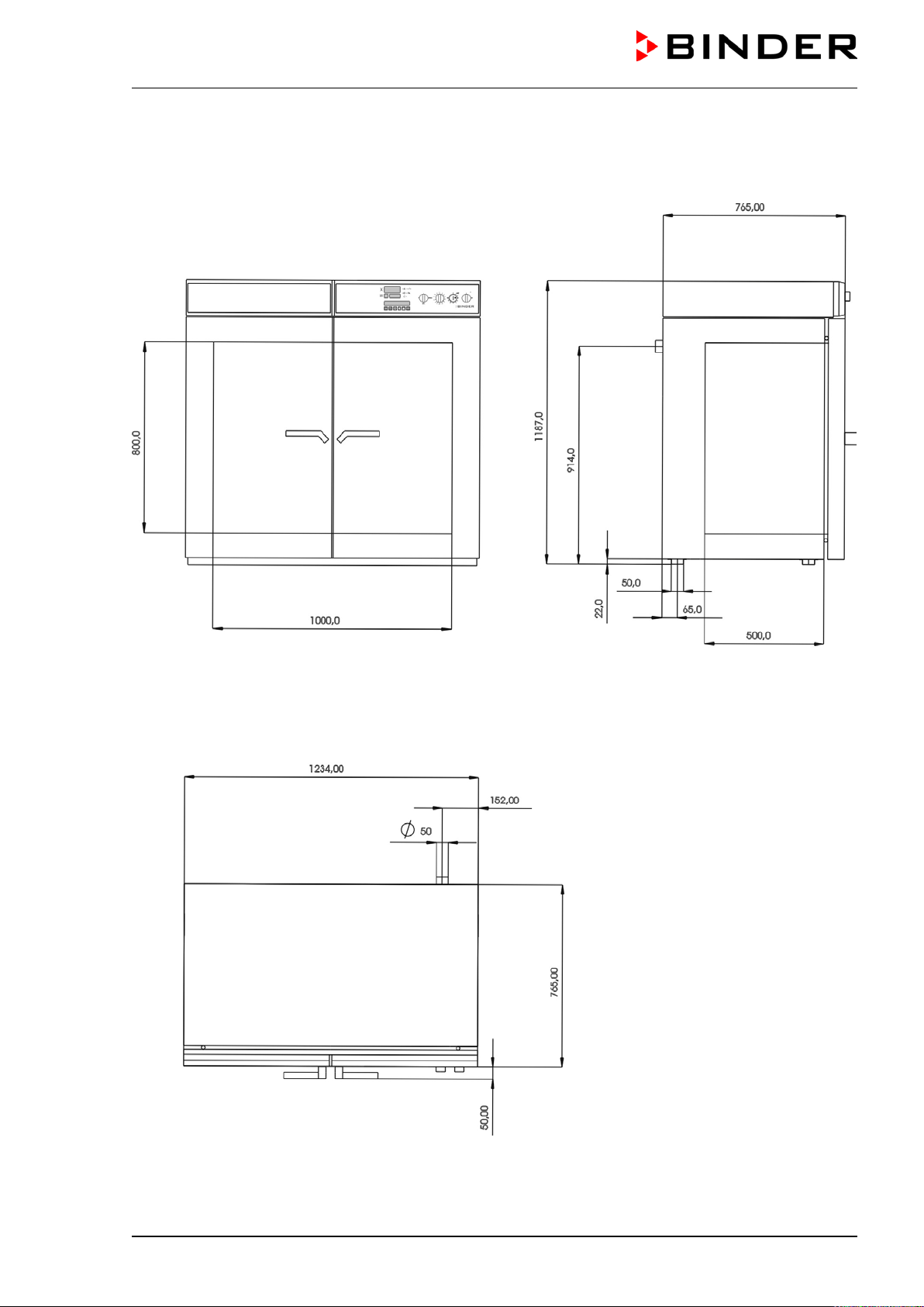
15.10
Dimensions M 400
Loading ...
Loading ...
Loading ...
File type: PDF
File name: 54948917_m-720.pdf
File size: 5.51 MB
File Language: English
Pages: 71
Author: Binder
Published:
2021-08-19
Updated: 2023-05-22
Download File
Table of Contents
×
1. Safety
4
1.1 Legal considerations
4
1.2 Structure of the safety instructions
4
1.2.1 Signal word panel
4
1.2.2 Safety alert symbol
5
1.2.3 Pictograms
5
1.2.4 Word message panel structure
6
1.3 Localization / position of safety labels on the chamber
6
1.4 Type plate
7
1.5 General safety instructions on installing and operating the chambers
8
1.6 Intended use
9
2. Chamber description
10
2.1 Chamber overview
11
2.2 Control panel
12
3. Completeness of delivery, transportation, storage, and installation
12
3.1 Unpacking, and checking equipment and completeness of delivery
12
3.2 Guidelines for safe lifting and transportation
13
3.3 Storage
13
3.4 Location of installation and ambient conditions
14
4. Installation and connections
15
4.1 Electrical connection
15
4.2 Connection to a suction plant (optional)
15
5. Start up
16
5.1 Function overview of the MB1 display program controller
16
5.2 Operating modes
16
5.3 Performance after power failures
17
5.4 Turning on the chamber
17
6. Controller MB1 settings
18
6.1 Selection of the menu language
18
6.2 Overview of program controller MB1 displays
19
6.3 Menu settings in the âUser-settingsâ menu
20
6.4 Menu settings in the âUser Levelâ menu
21
7. Graphic representation of the historical measurement (chart recorder function)
22
7.1 Setting the storage rate
24
8. Manual Mode
25
8.1 Entering the set point values
25
8.2 Performance after power failure in Manual Mode
26
9. Program operation
26
9.1 Menu-based program entry
27
9.2 Selecting between set-point ramp and set-point step
29
9.3 Program entry as set-point ramp or as set-point step
29
9.4 Information on programming different temperature transitions
32
9.5 Repetition of a section or several sections within a program
33
9.6 Performance after power failure in Program Mode
33
9.7 Starting a previously entered program
34
9.8 Deleting a program
34
9.9 Temperature profile template
35
9.10 Program table template
36
10. Temperature safety devices
37
10.1 Temperature safety device class 2 (DIN 12880)
37
10.2 Temperature safety device class 3.1 (DIN 12880) (available via BINDER INDIVIDUAL customized solutions)
38
11. Options
39
11.1 APT-COM⢠4 Multi Management Software (option)
39
11.2 Ethernet interface
39
11.3 HEPA fresh air filter (option)
39
11.4 Data logger kit (option)
40
11.5 Additional flexible Pt100-temperature sensor (option)
40
11.6 Analog output for temperature (option)
40
11.7 Additional measuring channel for digital object temperature indicator with flexible temperature sensor Pt 100 (option)
41
11.8 Mostly gas-tight version (option for M 53 and M 115)
41
11.9 Inert gas connection with mostly gas-tight version (option for M 53 and M 115)
42
11.10 Keyboard locking (option)
44
12. Maintenance, cleaning, and service
44
12.1 Maintenance intervals, service
44
12.2 Cleaning and decontamination
45
12.2.1 Cleaning
45
12.2.2 Decontamination
47
12.3 Sending the chamber back to BINDER GmbH
48
13. Disposal
48
13.1 Disposal of the transport packing
48
13.2 Decommissioning
49
13.3 Disposal of the chamber in the Federal Republic of Germany
49
13.4 Disposal of the chamber in the member states of the EU except for the Federal Republic of Germany
50
13.5 Disposal of the chamber in non-member states of the EU
51
14. Troubleshooting
52
15. Technical description
53
15.1 Factory calibration and adjustment
53
15.2 Definition of usable volume
53
15.3 Over current protection
54
15.4 Technical data
54
15.5 Equipment and options (extract)
56
15.6 Accessories and spare parts (extract)
57
15.7 Dimensions M 53
58
15.8 Dimensions M 115
59
15.9 Dimensions M 240
60
15.10 Dimensions M 400
61
15.11 Dimensions M 720
62
16. EU Declaration of Conformity
63
17. Product registration
65
18. Contamination clearance certificate
66
18.1 For chambers located outside the USA and Canada
66
18.2 For chambers located in the USA and Canada
69
Search:
×
Search