Loading ...
Loading ...
Loading ...
18
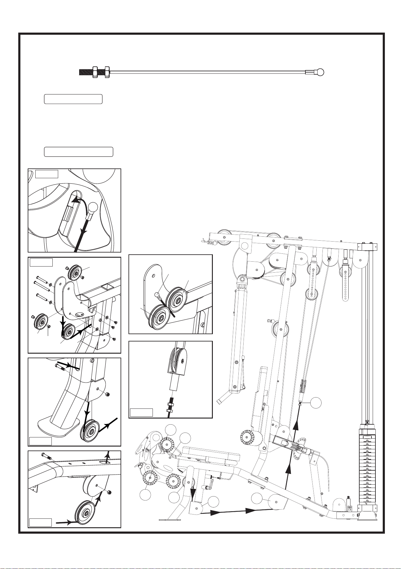
STEP 9 INSTALL LEG EXTENSION CABLE
LEG EXTENSION CABLE (84)
E1
E4
E5
E3
E2
E6
E7
Threaded End Steel Ball End
E2
E1
E3
STEP1
101
1
101
24
101
170
134
1
100
170
134
1
E3
E2
1
101
118
118
101
141
141
164
140
147
164
147
E4
101
118
22
1. See Fig. E1 & E2 Hook the steel ball end of the LEG EXTENSION CABLE (84) into the groove
in the LEG CURL CAM (22), and then route the cable in between two Pulleys E2 and E3 and
secure using one 3/8" X 75L FLAT PIN BOLT (141), four 3/8" SMALLER WASHERS (164) and
one M6 X 12L MALE SCREW (147) each, as shown in FIG STEP 1. Continue routing cable
down and around Pulley E4 mounted in a slot in the front of the MAIN FRAME (1) using one
3/8" X 75L FLAT PIN BOLT (141) and one M6 X 12L MALE SCREW (147).
2. See Fig. E5,E6 & E7 Route the cable down around Pulley E5 mounted under the SEAT ADJ.
FRAME (12), and secure using one 3/8" X 1-3/4" HEX BOLT (134) and one 3/8" NYLA-NUT
(170). Route the cable around Pulley E6 mounted under rear part of
the MAIN FRAME (1) and secure using one 4-1/2" PULLEY (100),
one 3/8" X 1-3/4" HEX BOLT (134) and one 3/8" NYLA-NUT (170).
Screw the threaded bolt-end into the SINGLE PULLEY BLOCK (24).
Note: The Threaded end is an adjustment point. It should be threaded
in a minimum of one third of the way into the SINGLE PULLEY
BLOCK (24). Tighten this cable so that it is very tight, but
does not lift the
TOP PLATE
from the weight stack.
Fig. E1
Fig. E2
Fig. E5
Fig. E7
Fig. E6
Loading ...
Loading ...
Loading ...