
Loading ...
Loading ...
Loading ...
17
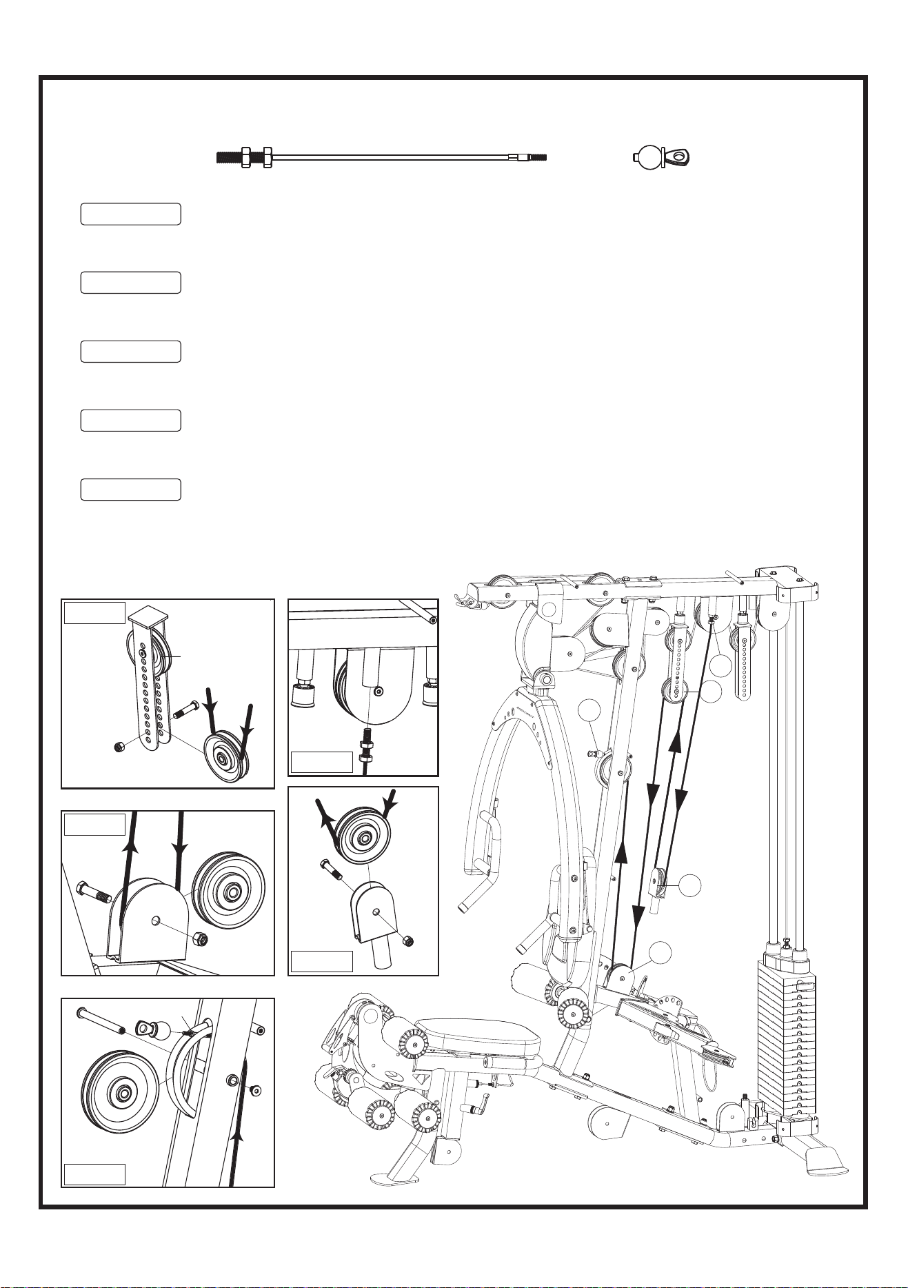
STEP 8 AB CRUNCH CABLE INSTALLMENT
A5
A4
A3
AB CRUNCH CABLE (83) REMOVABLE END (83A)
Bolt-end
100
147
83A
83
140
3
A1
A2
4
100
134
170
23
T8
101
170
134
19
24
100
134
170
1. See Fig. A1 Screw the Bolt-end of the AB CRUNCH CABLE (83) at least one-third of the way
into the threaded receptor welded to the TOP FRAME (4). This Bolt-end is an adjustment
point if needed once all of the cables have been installed. Be sure to tighten the Jam-nut.
2. See Fig. A2 Install one 4-1/2" PULLEY (100) into SINGLE PULLEY BLOCK (24) using one
3/8" X 1-3/4" HEX BOLT (134) and one 3/8" NYLA-NUT (170). Tighten. Route the cable
down to Pulley A2.
3. See Fig. A3 Install one 4-1/2" PULLEY (100) into the second hole up of ADJ. PULLEY
BLOCK (23) and secure with one 3/8" X 1-3/4" HEX BOLT (134) and one 3/8" NYLA-NUT
(170). Tighten. Continue routing the cable up to the Pulley A3.
4. See Fig. A4 Install one 3-1/2" PULLEY (101) into the CABLE ARM CONNECTOR (19), using
one 3/8" X 1-3/4" HEX BOLT (134) and one 3/8" NYLA-NUT (170). Tighten. Continue
routing the cable down to the Pulley A4.
5. See Fig. A5 Install one 4-1/2" PULLEY (100) into the FRONT UPRIGHT (3), using one 3/8" X
109.5L FLAT PIN BOLT (140) and one M6 X 12L MALE SCREW (147). Tighten. Continue
routing the cable up to and over the top of Pulley A5.
Install REMOVABLE END (83A) at A5. IMPORTANT! Make sure it is completely tightened!
Fig. A3
Fig. A4
Fig. A5
Fig. A2
Fig. A1
Loading ...
Loading ...
Loading ...