Loading ...
Loading ...
Loading ...
19
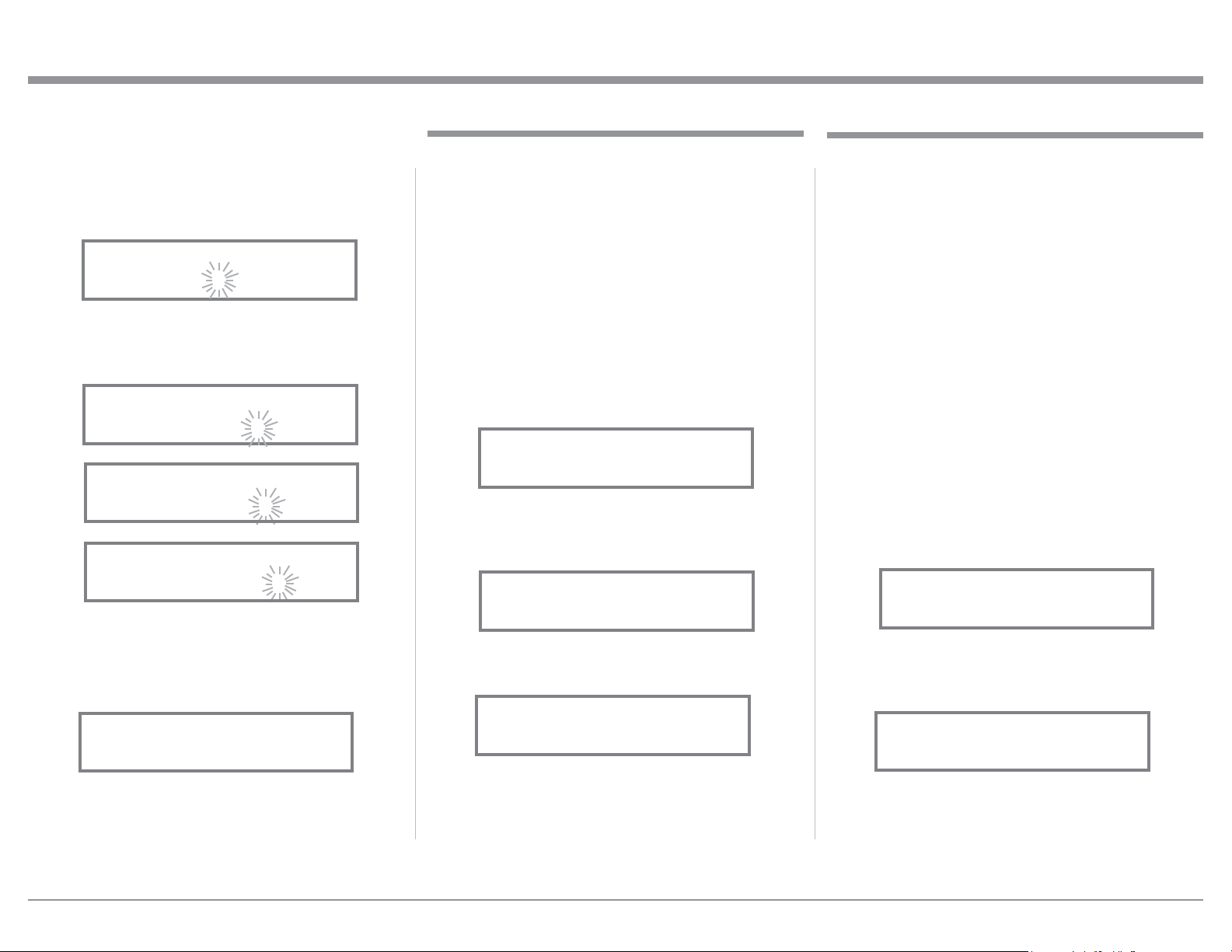
19. Rotate the INPUT Control until the “_” empty
space to the right of character I is flashing, then
rotate the VOLUME (ADJUST) Control to change
the “_” empty space to character to “A”. Refer to
figure 14.
20. Repeat step 19 until the new name of “ RENAME:
BAL, MEDIA SVR” is indicated on the Front
Panel Display. Refer to figures 15 thru 17.
21. To save the new name, press and hold in the IN-
PUT Control until “SETUP: MEDIA SVR , ON /
Rename” appears on the Front Panel Information
Display. Refer to figure 18.
22. Exit the SETUP Mode by several presses of the
INPUT Control.
Note: For convenience, an “Input Assignment Chart”
on a separate sheet “Mc5A/5B” has been pro-
vided to keep track of changes.
Setup, con’t
Figure 14
RENAME: BAL
>MEDIA <
Figure 18
Figure 18
SETUP: MEDIA SVR
On / Rename
Figure 16
RENAME: BAL
>MEDIA SV <
Fig ure 17
RENAME: BAL
>MEDIA SVR <
Figure 15
RENAME: BAL
>MEDIA S <
Data Ports
Data Port Connections between the MA5300 and a
McIntosh Source Component allow for basic function
control of the source component using the MA5300
supplied HR085 Remote Control. By default, all of the
four Data Ports are set to send the same Data to the
selected source. To dedicate a given Data Port for only
one source component (example, source component
connected to the BAL Input will be assigned to Data
Port 1) perform the following Steps:
1. Press and hold in the INPUT Control to enter the
SETUP MODE. Refer to figure 2 on page 17.
2. Rotate the INPUT Control until “SETUP: Data
Ports, (Hold INPUT)” appears on the Information
Display. Refer to figure 19.
3. Press and hold in the INPUT Control until “SET-
UP: DATA PORT 1, All Data” appears on the
Display. Refer to figure 20.
4. Rotate the VOLUME (ADJUST) Control to select
the “BAL” Input. Refer to figure 21.
5. In a similar manner, perform steps 3 and 4 to as-
sign any additional Data ports.
6. Exit the SETUP Mode by several presses of the
INPUT Control.
Figure 19
SETUP: Data Ports
(Hold INPUT)
Figure 20
SETUP: DATA PORT 1
All Data
Figure 21
SETUP: DATA PORT 1
BAL
When the MA5300 is part of a Home Theater or
Multichannel Audio System the Right and Left Front
Channels from an Audio/Video Processor or Surround
Decoder can “Passthru” from the assigned MA5300
Input, into the MA5300 Power Amplifier Circurity.
The “Passthru” Audio Signal is also available for a
separate external Power Amplifier(s) via the number
1 Preamplifier Output Jacks. The Setup Mode allows
selection of the specified MA5300 Input to be used
for the Right and Left Front Channels. In the example
below, the Right and Left Front Channels from the
Audio/Video Processsor will be connected to the UN-
BALANCED 6 INPUT Jacks on the MA5300. Refer
to page 9 for additional connection information.
Note: The Phono and Digital Inputs are not assign-
able as a Passthru Input.
1. Press and hold in the INPUT Control to enter the
SETUP MODE. Refer to figure 2 on page 17.
2. Rotate the INPUT Control until “SETUP: Passth-
ru, Off” appears on the Information Display.
Refer to figure 22.
3. Rotate the VOLUME (ADJUST) Control to select
“SETUP: Passthru, UNBAL 6” Input. Refer to
figure 23.
4. Exit the SETUP Mode by several presses of the
INPUT Control.
SETUP: Passthru
UNBAL 6
Figure 23
SETUP: Passthru
Off
Figure 22
Passthru
Loading ...
Loading ...
Loading ...