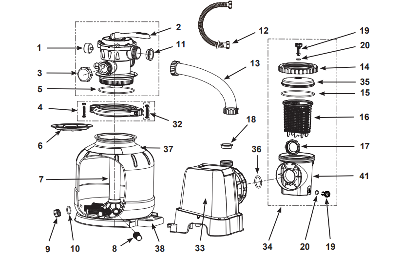
Before assembling your product, please take a few minutes to check the contents and become familiar with all the parts.
Parts shown on this page are supplied with the pool package and are shown here for assembly purposes only
NOTE: Drawings for illustration purpose only. Actual product may vary. Not to scale. No tools are required for the assembly.
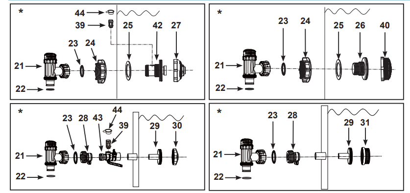
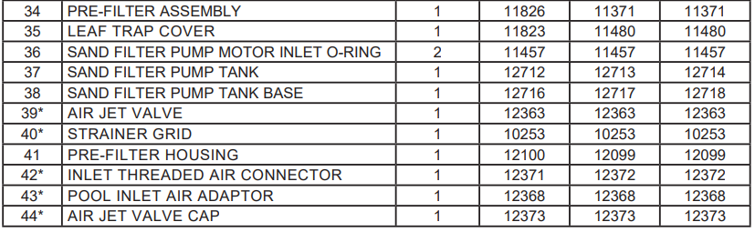
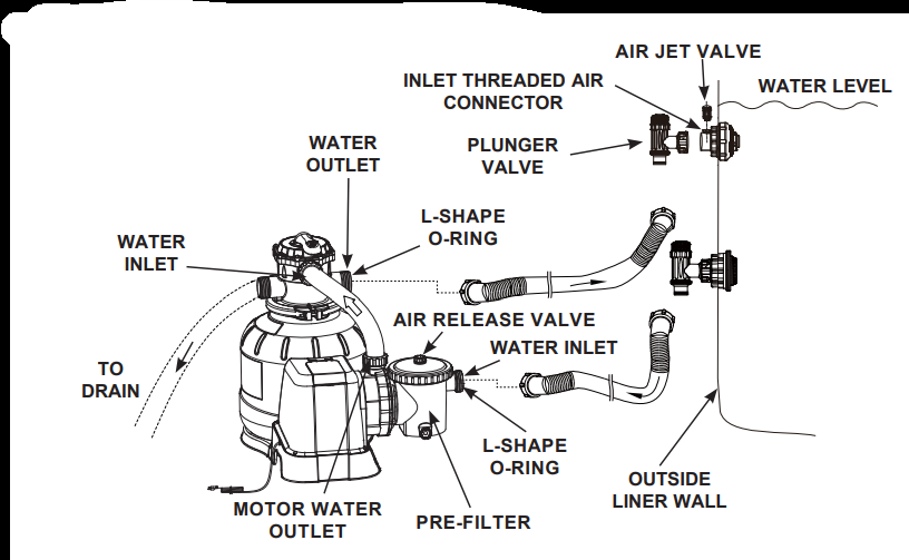
POOL OUTLET - STRAINER & PLUNGER VALVE SETUP (optional)
The strainer grid prevents large objects from jamming and/or damaging the filter pump. If your pool has an inflatable top ring, install the strainer, nozzle and plunger valve before inflating the pool liner top ring. The part numbers here onward refer to the parts depicted in the Parts List section of this manual. To install, do the following:
1. In a counter-clockwise motion unscrew plunger valve union from the threaded strainer connector (26) (see drawing 1). Be careful not to lose the step rubber washer (23). Place the plunger valve on the ground in a safe place.
2. In a counter-clockwise motion unscrew the strainer nut (24) from the threaded connector (26). Leave the flat washer (25) on the connector (26).
3. Install the strainer and plunger valve at the lower position of pool outlet (marked "+"). From the inside of the pool liner insert the connector (26) into one of the pre-cut holes with the washer remaining on the connector to be placed against the inside of the liner wall.
4. Before assembly, lubricate the threads with a petroleum jelly. With the flat side of the strainer nut (24) facing the outside wall of the liner in a clockwise motion screw the strainer nut (24) back onto the threaded connector (26) (see drawing 2).
5. Finger tighten the strainer nut (24) onto the threaded connector (26).
6. Grasp the plunger valve assembly. Make sure the step washer (23) is in place.
7. In a clockwise motion screw the plunger valve union back onto the threaded connector (26) (see drawing 3).
8. In a clockwise motion turn the plunger valve handle to close position. Ensure the plunger valve is securely closed. This will prevent water from flowing out during filling of the pool (see drawing 4).
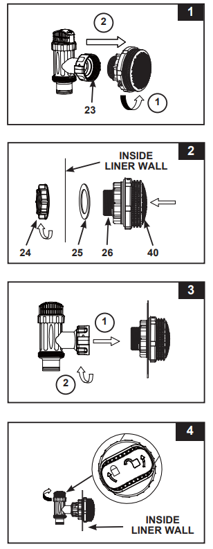
POOL INLET - NOZZLE & PLUNGER VALVE SETUP (optional)
1. In a counter-clockwise motion unscrew plunger valve union from the inlet threaded air connector (42) (see drawing 5). Be careful not to lose the step rubber washer (23). Place the plunger valve on the ground in a safe place.
2. In a counter-clockwise motion unscrew the strainer nut (24) from the inlet threaded air connector (42). Leave the flat washer (25) on the connector (42).
3. Install the nozzle and plunger valve at the upper position of pool inlet. From the inside of the pool liner insert the nozzle union (27 & 42) into one of the pre-cut holes with the washer remaining on the connector to be placed against the inside of the liner wall.
4. Before assembly, lubricate the threads with a petroleum jelly. Then, with the flat side of the strainer nut (24) facing the outside wall of the liner in a clockwise motion screw the strainer nut (24) back onto the inlet threaded air connector (42) (see drawing 6).
5. Finger tighten the adjustable pool inlet jet nozzle (27) and the strainer nut (24) onto the inlet threaded air connector (42).
6. Grasp the plunger valve assembly. Make sure the step washer (23) is in place.
7. Screw the air jet valve (39) over the inlet threaded air connector (42). NOTE: Make sure the air jet valve is securely tighten and facing up. In a clockwise motion screw the plunger valve union back onto the inlet threaded air connector (42) (see drawing 7).
8. In a clockwise motion turn the plunger valve handle to close position. Ensure the plunger valve is securely closed. This will prevent water from flowing out during filling of the pool (see drawing 8).
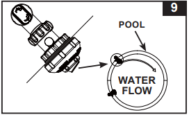
9. Adjust the direction of nozzle head pointing away from the pool outlet for a better circulation result (see drawing 9).
10. The pool liner is now ready to fill with water. Consult the above-ground-pool owner’s manual for filling instructions.
NOTE: Do not cover the air jet valve (39) with the valve cap (44) under normal situation or when the pump is operating. See Troubleshooting Guide section for more details.
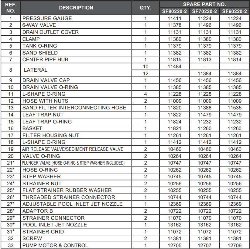
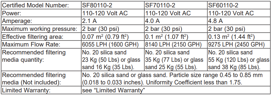
PRODUCT SPECIFICATIONS
The sand filter removes suspended particles but does not sanitize your pool. Pool chemistry is a specialized area and you should consult your local pool service specialist for details.
SETUP INSTRUCTIONS
TOOLS REQUIRED: One (1) Phillips screwdriver
Pump location and mounting:
• The system must be installed on a solid level and vibration-free base.
• Provide a location protected from the weather, moisture, flooding and freezing temperature.
• Provide adequate access, space and lighting for routine maintenance.
• Pump motor requires free circulation of air for cooling. Do not install the pump in a damp or non-ventilated location.
A team of 2 or more people is recommended for setting up this product.
Motor pre-filtering assembly setup:
1. Remove the sand filter and its accessories from the packaging carefully and inspect for any visible damage.
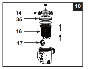
2. In a counter-clockwise motion unscrew the leaf trap cover (35) from the pre-filter housing. Take out the basket (16) and filter housing nut (17) (see drawing 10).
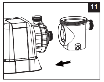
3. Connect the pre-filter housing to the motor water inlet. Note: Align the connector in the pre-filter housing with the water inlet on the motor (see drawing 11).
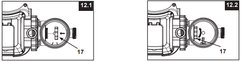
4. In a clockwise motion screw filter housing nut (17) onto the motor water inlet (see drawings 12.1 & 12.2).
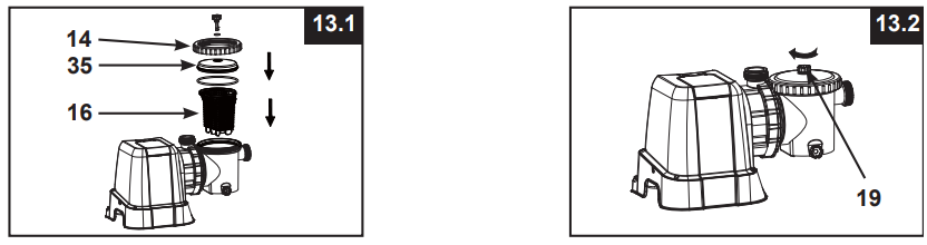
5. Replace the basket (16) and leaf trap cover (35) back to the pre-filter housing (see drawings 13.1 & 13.2).
Sand tank installation:
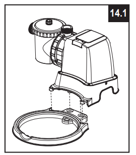
1. Place the tank support base at the selected location.
2. Place the tank on the tank support base (see drawing 14.1).
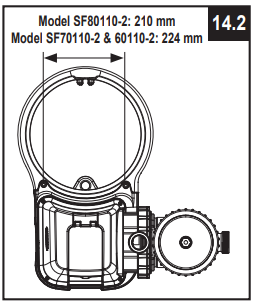
3. Connect the motor pre-filtering assembly unit to the tank support base (see drawing 14.2).
NOTE: Ensure the pre-filter housing water inlet hose connection is facing towards the pool.
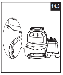
IMPORTANT: Some countries, especially in the European community, require the product to be secured to the ground or to a base in a permanent upright position. Check your local authorities to determine if there is a regulation in your area regarding above-the-ground swimming pool filter-pumps. If yes, then the product can be mounted to a platform using the two holes located in the base. See drawing 14.3
The product can be mounted on a cement base or onto a wooden platform to prevent accidental falling over.
• The mounting holes are 6.4 mm in diameter and spaced 210 mm for model SF80110-2 (spaced 224 mm for model SF70110-2 & SF60110-2) apart.
• Use two bolts and lock nuts with a maximum of 6.4 mm in diameter.
Sand loading:
IMPORTANT: Use No. 20 silica sand or glass sand with particle size range 0.45 to 0.85 mm (0.018 to 0.033 inches) and a Uniformity Coefficient less than 1.75.
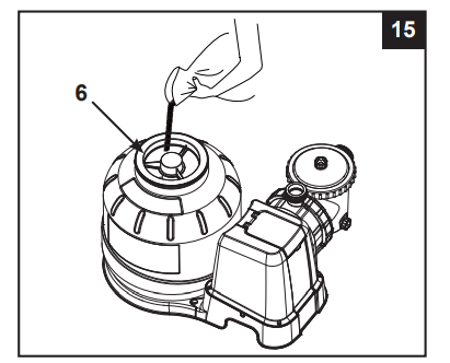
NOTE: Before loading the tank with sand, ensure the center pipe hub assembly is securely in place at the bottom of the tank, and vertically centered inside the tank.
1. Place the sand shield (6) over the top of the center pipe. Pour the sand into the tank at a slow rate (see drawing 15).
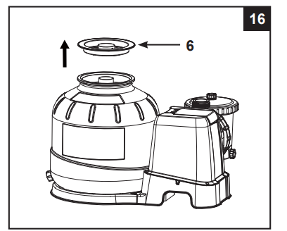
2. Fill the tank approximately half way, remove the sand shield (6) from the top (see drawing 16).
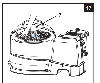
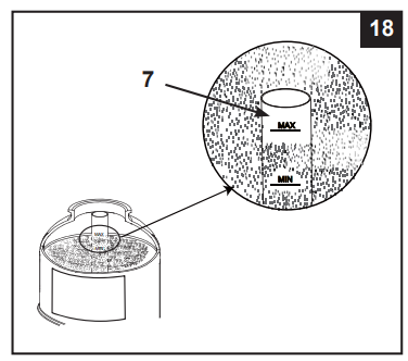
3. Evenly distribute the sand inside the tank, then fill the tank with some water to provide a cushioning effect when the remaining sand is poured in. This prevents the center pipe hub (7) from excessive shock (see drawing 17). Place the sand shield (6) back and continue to pour the sand into the tank.
4. Sand shall be filled between the “MAX” and “MIN” marked gauge on the center pipe (see drawings18).
5. Remove the sand shield (6) (see drawing 16) and evenly spread and level out the sand by hand (see drawing 17).
6. Wash away all sand around the top edge of the tank.
6-way valve installation:
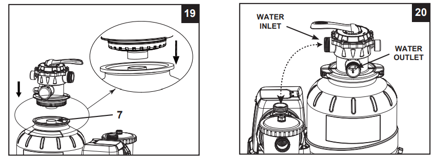
1. Lower the 6-way valve over the tank slowly, and ensure the bypass pipe protruding underneath the 6-way valve fits securely into the center pipe hub (7) top opening (see drawing 19).
IMPORTANT: There are three hose connection ports on the 6-way valve, ensure the outlet connection (from filter to the pool) on the valve is facing towards the pool, and the inlet connection (from motor to valve) is aligned with the motor outlet (see drawing 20).
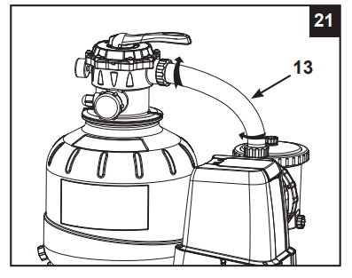
2. Place an L-shape o-ring (11) on the 6-way valve inlet connection and on the pump motor outlet. In a clockwise motion connect the sand filter interconnecting hose (13) between the pump motor outlet and the 6-way valve inlet connection (see drawing 21).
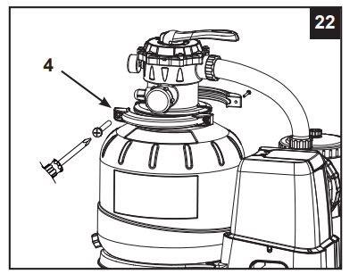
3. Remove the clamp bolt, and install the clamp around the tank and 6-way valve flanges, then replace the clamp bolt and use a phillips screwdriver (not included) to tighten it (see drawing 22).
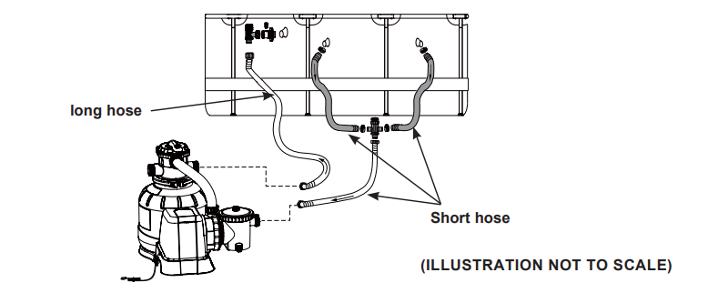
SAND FILTER PUMP HOSE CONNECTION SETUP
The 6-way valve has three hose connection ports.
1. Connect one hose (12) end to the pre-filter inlet and the other end of the hose to the lower plunger valve with the strainer. Ensure the hose nuts are securely tightened.
2. Connect the second hose (12) between the 6-way valve water outlet and the upper plunger valve with the inlet-nozzle. Ensure the hose nuts are securely tighten.
3. The third hose connection port (drain/waste outlet) on the 6-way valve shall be directed to a proper draining receptacle using a hose or pipe (not provided). Remove the drain cap before attaching the drain/waste hose or pipe.
4. The sand filter pump is now ready to filter the pool.
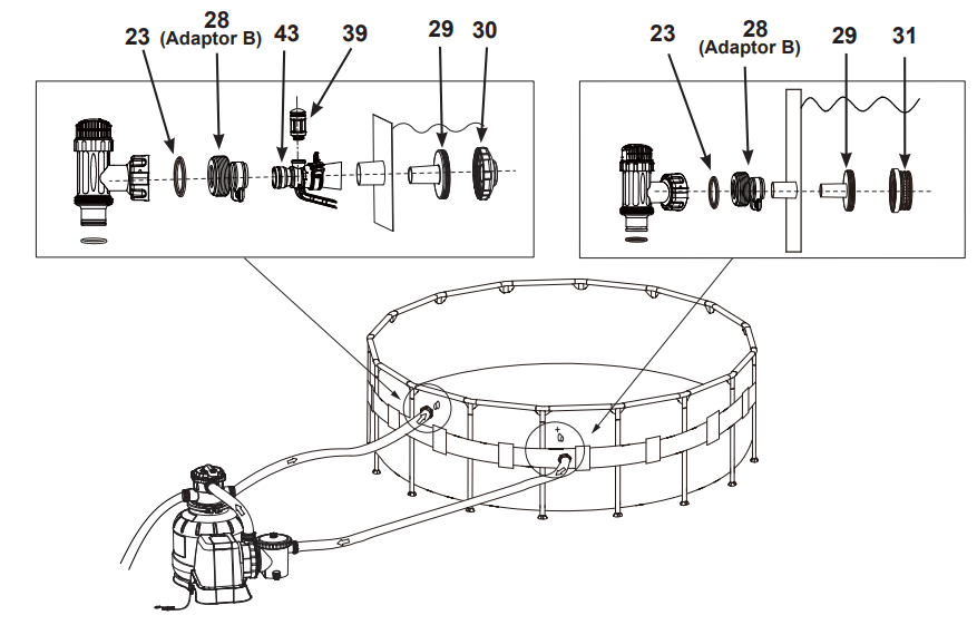
For Pools with Dual Suction Outlets Configuration:
In order to comply with the requirement of the Virginia Grahame Baker Act (for USA and Canada), your pool is designed with dual suction outlets and one inlet fittings. Parts in grey highlight on this page are supplied with the pool set package and are shown here for assembly purposes only. If this pump was purchased as part of a pool set, refer to the pool owner’s manual for more details.
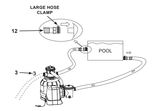
For NON-INTEX pool:
Connect the hose (12) to the pool inlet/outlet connection with a large hose clamp. Tighten securely.
For INTEX pool with 1-1/4” (32mm) connections/hoses:
Make sure the air jet valve (39) is securely tighten onto the pool inlet air adaptor (43) and facing up.
OPERATING INSTRUCTIONS
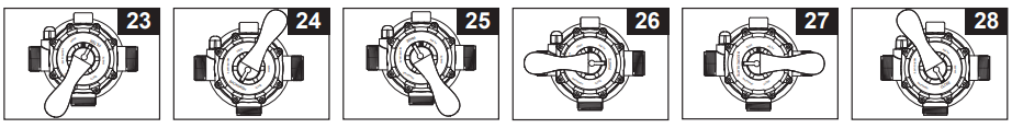
6-way valve positions and function:
Valve Position
Function
Water Flow Direction
FILTER (see drawing 23)
Normal filtration and regular vacuuming of pool
From pump through filter media to pool
BACKWASH (see drawing 24)
Reverses water flow to clean filter media
From pump through filter media to valve waste/drain outlet
RINSE (see drawing 25)
For initial startup cleaning of the sand, and leveling the sand bed after backwashing
From pump through filter media to valve waste/drain outlet
WASTE (see drawing 26)
For vacuuming directly to waste, lowering pool level or to drain the pool
From pump to valve waste/drain outlet bypassing the filter media
RECIRCULATE (see drawing 27)
For circulating water back to pool without going through the filter medi
From pump through valve to pool bypassing the filter media
CLOSED (see drawing 28)
Shuts off all flow to filter and pool “Do not use this setting with pump running”
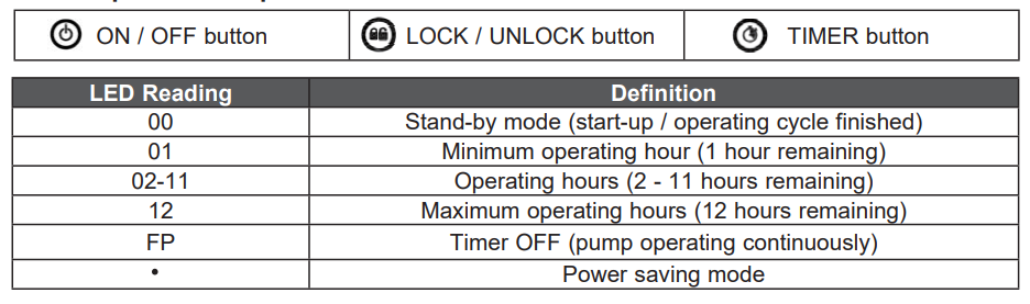
Control panel description:
Initial startup and operation:
Before operating, be sure that:
• All the hoses have been connected and tightened securely, and correct amount of filter sand have been loaded.
• The entire system is connected to a grounding type receptacle protected by a ground-fault circuit interrupter (GFCI) or residual current device (RCD).
1. Turn both plunger valve handles fully counter-clockwise until they stop. This opens the valves to allow water to flow into the sand filter pump. With water flowing into sand filter pump, the water pressure will allow the air trapped inside to escape from the air release valves (19). When all the air has escaped water will flow out of the valves (19). When this occurs gently finger tighten the valves (19) in a clockwise direction.
2. Ensure the drain/waste outlet on the 6-way valve is not covered and directed to a proper draining receptacle.
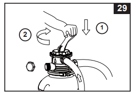
3. Ensure the pump is off, depress the 6-way valve and turn it to the “BACKWASH” position (see drawings 24 & 29). IMPORTANT: To prevent damage to the 6-way valve, always depress the valve handle before turning. Always switch off pump before changing the 6-way valve position.
4. Press to switch on the system, and then press to set the operating TIMER hours (see “Operating the system under TIMER mode or manually” section for details). Water is circulating backward through the sand media and to waste/drain outlet. Backwash until a clear flow of water is observed in the waste/ drain outlet or through the drain sediment window.
NOTE: If the LED display flashes “00”, the device is in stand-by mode and the pump will not operate. The initial backwash of the filter is recommended to remove any impurities or fine sand particles in the sand media.
5. Switch off the pump, change the 6-way valve to “RINSE” position (see drawing 25).
6. Switch on the pump and run the pump for about one minute to level out the sand bed after backwashing the sand media.
7. Switch off the pump, change the 6-way valve to “FILTER” position (see drawing 23).
8. Switch on the pump. The system is now operating in the normal filtering mode. Run the pump until the desired pool water clearance is obtained and no more than 12 hours per day. For the initial startup, it is recommended setting the system to a longer TIMER operating hours or “FP” for the pump to operate continuously without the TIMER.
9. Record the initial pressure gauge reading when the filter media is clean.
NOTE: During initial setup of the system, it may be necessary to backwash frequently due to unusual heavy dirt present in the water and sand. After that, as the filter removes dirt and impurities from the pool water, the accumulated dirt in the sand media will cause the pressure to rise and the flow to diminish. If there is no vacuuming device attached to the system and the pressure gauge reading is in the yellow zone it is time to backwash the sand media, see “BACKWASH” under “initial startup and operation” section. Vacuuming device (i.e. Intex auto pool cleaner) attached to the system may also cause the flow to diminish and the pressure to rise. Remove any vacuuming device from the system and check if the pressure gauge reading has dropped from the yellow zone to the green zone.
10. Monitor the pressure gauge reading, and check that the inlet and outlet openings are not obstructed on a weekly basis. If the pressure gauge indicates yellow it is time to backwash the filter media.
MOTOR PRE-FILTER CLEANING AND MAINTENANCE
1. Make sure the filter pump is switched off, then disconnect the power cord from the electrical outlet.
2. Turn both plunger valve handles fully clockwise until they stop. This closes the valve, prevents the water from flowing out of the pool.
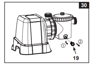
3. Release the pressure first by opening the sediment release valve (19) located on the lower side of the pre-filter housing (see drawing 30).
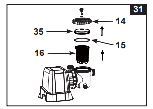
4. In a counter-clockwise motion unscrew the leaf trap cover (35), then remove the basket (16) and leaf trap o-ring (15) from the pre-filter housing (see drawing 31).
5. Empty and flush the basket using a garden hose, may use a plastic brush to remove deposits from the basket. Do not use metal brush.
6. Clean and rinse the inside of the pre-filter housing and the leaf trap O-ring with a garden hose.
7. Reinstall the leaf trap O-ring, basket and leaf trap cover to the pre-filter housing.
8. Close the sediment release valve (19) back.
POOL CARE & CHEMICALS
• All pools require care to keep the water clear and hygienically clean. With proper chemical control, your filter will help attain this objective. Consult your pool supply dealer for instructions regarding the proper use of chlorine, algaecide and other chemical agents required for sparkling clear water.
• Keep pool chemicals away from children.
• Do not replenish chemicals in pool while pool is occupied. Skin or eye irritations could occur.
• Daily pH checking and chemical treatment of the water is very important and cannot be overemphasized. Chlorine, algaecide and maintenance of proper pH levels are required when filling the pool as well as during the season. Consult your local swimming pool supply store for instructions.
• The season's first filling of the pool may have brackish water requiring extra water additives and extra filtering time. Do not allow swimming in pool until the pH level is balanced. Consult your local swimming pool supply store for instructions.
• Chlorinated water may damage lawns, gardens or shrubbery as children play in the pool and splash water outside the pool. Lawn areas underneath the pool liner will be destroyed. Note that some types of grass may grow through the liner.
• Filter run time depends on pool size, weather and usage level. Experiment with various run times so as to produce clean clear water.
1. Before emptying your pool for long term storage, or relocation, be sure the water is directed towards an acceptable drain water receptacle away from the house. Check local regulations for specific directions regarding disposal of swimming pool water.
2. Switch off the unit, and disconnect power cord from electrical outlet.
3. When the pool is empty, disconnect all hoses from pump and plunger valves and remove the strainers/ plunger valves from the pool wall.
4. In a counter clockwise motion unscrew the drain valve cap (9) from the drain valve to thoroughly drain the tank. The drain valve is located at the bottom of the filter tank.
5. Disassemble the pump motor from the tank base.
6. Leave sand filter pump pieces and hoses outside to thoroughly air dry.
7. Coat the following o-rings and washers with petroleum jelly for long term storage:
• L-shape o-ring (11 & 18).
• Pump hose O-rings (22).
• Strainer valve assembly step washers (23).
• Flat strainer rubber washers (25).
8. Depress the 6-way valve handle and rotate so as to set the pointer on the valve top “N” position. This allows the water to drain from the valve. Leave the 6-way valve in this inactive position.
9. It is best to place all dry pieces and pump motor in the original packaging for storage. To avoid condensation or corrosion problem, do not cover or wrap pump motor with plastic bags.
10. Store the pump motor and accessories in a dry place. The storage's temperature should be controlled, between 0 degrees Celsius (32 degrees Fahrenheit) and 40 degrees Celsius (104 degrees Fahrenheit).
TROUBLESHOOTING GUIDE
TROUBLE
CAUSE
SOLUTION
FILTER MOTOR FAILS TO START
• The motor is not plugged in.
• Line cord must be plugged into a 3 wire outlet that is protected by a Class A Ground Fault Circuit Interrupter, or RCD.
• The GFCI/RCD circuit breaker is tripped.
• Reset circuit breaker. If circuit breaker trips repeatedly, your electrical system may have a defect. Turn off circuit breaker and call an electrician to correct the problem.
• Motor too hot and overload protection is shut off.
• Let the motor cool down and restart again.
FILTER DOESN’T CLEAN POOL
• Improper chlorine or pH levels.
• Adjust the chlorine and pH level. Consult your local swimming pool supply stores.
• No filtering media in tank.
• Load with filter sand, see “sand loading instructions”.
• Wrong 6-way valve setting position.
• Set valve to “FILTER” position.
• Excessively dirty pool.
• Operate the filter for longer periods.
• The strainer screen is restricting the water flow.
• Clean the strainer screen at the inlet.
FILTER DOESN’T PUMP WATER OR FLOW IS VERY SLOW
• Clogged inlet or discharge.
• Clear any obstructions in the intake hose by discharging it inside pool wall.
• An air leak on the intake line.
• Tighten hose nuts, check hoses for damage, check pool water level.
• Excessively dirty pool.
• Clean the pre-filtering basket more often.
• Sand media clogged with dirt.
• Backwash filter.
• Nozzle and strainer connections are reversed.
• Install the nozzle at the upper position of the pool inlet, and the strainer at the lower position of the pool outlet.
• Crusting or caking on the filtering sand surface.
• Remove about 1” of sand if necessary.
• Pool vacuuming device attached to the system.
• Remove any pool vacuuming device attached to the system line.
• Inlet threaded air connector connected to the wrong hole on the liner.
• Make sure the inlet threaded air connector is connected to the pool inlet upper hole.
PUMP DOESN’T WORK
• Low water level.
• Fill pool to correct water level.
• Strainer screen clogged up.
• Clean strainer screens at pool inlet.
• An air leak on the intake hose.
• Tighten hose nuts, check hose for damage.
• Faulty motor or the impeller is jammed
• Contact Intex service center.
6-WAY VALVE/ COVER LEAKING
• Sand tank o-ring missing.
• Remove 6-way valve cover and ensure the o-ring is in place.
• Ensure o-ring/L-shape o-ring is in place and not damaged.
TIMER IS INACCURATE OR TIMER CAN'T BE SET
• Possible inner timer defective.
• Turn off the pump and restart 5 minutes later.
• Re-set the timer.
• Contact Intex service center.
PRESSURE GAUGE DOESN’T WORK
• Clogged inlet of the pressure gauge.
• Clear any obstructions in the intake by unscrewing it from the 6-way valve.
• Pressure gauge damage
• Contact Intex service center.
SAND IS FLOWING BACK INTO THE POOL
• Sand is too small.
• Use only No. 20 silica sand with particle size range 0.45 to 0.85 mm (0.018 to 0.033 inches) and a Uniformity Coefficient less than 1.75.
• Sand bed is calcified.
• Change sand.
INLET THREADED AIR CONNECTOR/AIR JET VALVE LEAKING
• Plunger valve not well-fitted.
• Tighten or reinstall plunger valve.
• Air jet valve is not tight and facing up.
• Tighten air jet valve and make sure it’s facing up.
• Air jet valve internal seal blocked.
• Turn pump ON and run for few seconds, then turn OFF, repeat 3 times.
• Air jet valve internal seal dirty.
• Remove air jet valve, flush dirt out with water and replace valve back.
• Air jet valve broken.
• Replace a new air jet valve.
SMALL LEAK FROM AIR JET VALVE WHEN PUMP IS ON
• Accessories attached to the water circulation line.
• Remove all the accessories (such as solar mat, auto pool cleaner, LED light) from the water circulation line and place the air jet valve cap (44) over the air jet valve (39). Do not cover the air jet valve (39) with the valve cap (44) under normal situation or when the pump is operating.
COMMON POOL PROBLEMS
PROBLEM
DESCRIPTION
CAUSE
SOLUTION
ALGAE
• Greenish water.
• Green or black spots on pool liner.
• Pool liner is slippery and/or has a bad odor.
• Chlorine and pH levels need adjustment.
• Super chlorinate with shock treatment. Correct pH to your pool store's recommended level.
• Vacuum pool bottom.
• Maintain proper chlorine level.
COLORED WATER
• Water turns blue, brown, or black when first treated with chlorine.
• Copper, iron or maganese in water being oxidized by the added chlorine.
• Adjust pH level to the recommended level.
• Run filter until water is clear.
FLOATING MATTER IN WATER
• Water is cloudy or milky.
• "Hard water" caused by a too high pH level.
• Chlorine content is low.
• Foreign matter in water.
• Correct the pH level. Check with your pool dealer for advice.
 to switch on the system, and then press
  to set the operating TIMER hours (see “Operating the system under TIMER mode or manually” section for details). Water is circulating backward through the sand media and to waste/drain outlet. Backwash until a clear flow of water is observed in the waste/ drain outlet or through the drain sediment window.