User Manual
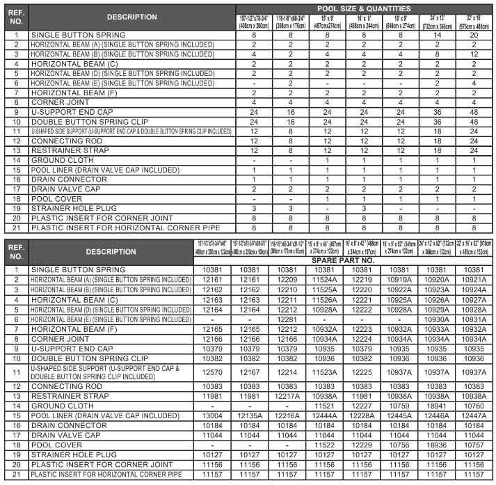
PARTS REFERENCE
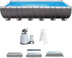
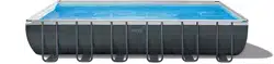
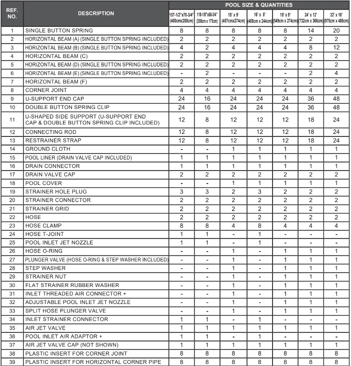
Before assembling your product, please take a few minutes to check the contents and become familiar with all the parts.
For Pools with Dual Suction Outlets Configuration:
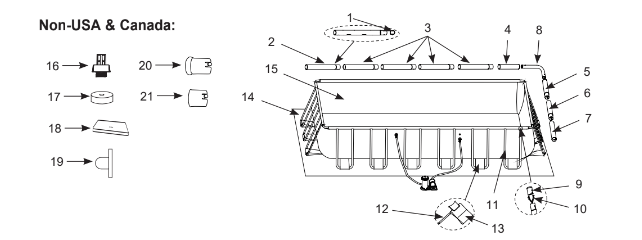
In order to comply with the requirement of the Virginia Grahame Baker Act (for USA and Canada), your pool is designed with dual suction outlets and one inlet fittings. Overview of the dual suction outlets configuration is as follow
NOTE: Drawings for illustration purpose only. Actual product may vary. Not to scale.
If applicable, depending on the size of the filter pump fitted with your pool, you must quote the model number shown on the filter pump housing to order the correct size of “Pool Inlet Air Adaptor” or “Inlet Threaded Air Connector” replacement part.
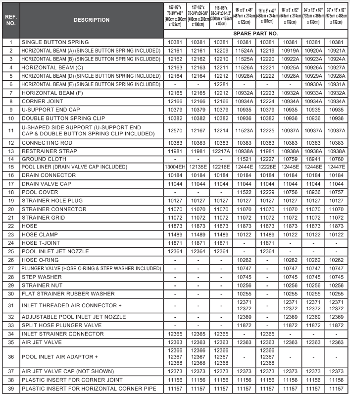
If applicable, depending on the size of the filter pump fitted with your pool, you must quote the model number shown on the filter pump housing to order the correct size of “Pool Inlet Air Adaptor” or “Inlet Threaded Air Connector” replacement part.
NOTE: Drawings for illustration purpose only. Actual product may vary. Not to scale.
POOL SETUP
IMPORTANT SITE SELECTION AND GROUND PREPARATION INFORMATION
WARNING
- The pool location must allow you to secure all doors, windows, and safety barriers to prevent unauthorized, unintentional or unsupervised pool entry.
- Install a safety barrier that will eliminate access to the pool for young children and pets.
- Failure to set up the pool on flat, level, compact ground and to assemble and fill with water in accordance with the following instructions could result in the pool’s collapse or the possibility that a person lounging in the pool could be swept out/ejected, resulting in serious injury or property damage.
- Risk of electric shock: connect the filter pump only to a grounding type receptacle protected by a ground-fault circuit interrupter (GFCI). To reduce the risk of an electrical shock, do not use extension cords, timers, plug adapters or converter plugs to connect the pump to an electrical supply. Always provide a properly located outlet. Locate the cord where it cannot be damaged by lawn mowers, hedge trimmers, and other equipment. See the filter pump manual for additional warnings and instructions.
- Risk of serious injury: do not attempt to assemble pool in high wind conditions.
Select an outdoor location for the pool with the following requirements in mind:
- The area where the pool is to be set up must be absolutely flat and level. Do not set up the pool on a slope or inclined surface.
- The ground surface must be compacted and firm enough to withstand the pressure and weight of a fully set up pool. Do Not set up the pool on mud, sand, soft or loose soil conditions.
- Do not set up the pool on a deck, balcony or platform, which may collapse under the weight of the filled pool.
- The pool requires at least 5 - 6 feet (1.5 - 2.0 m) of space all around pool from objects that a child could climb on to gain access to the pool.
- Grass under the pool will be damaged. Splash out chlorinated pool water could damage the surrounding vegetation.
- If the ground is not concrete (i.e., if it is asphalt, lawn or earth) you must place a piece of pressure-treated wood, size 15” x 15” x 1.2” (38 x 38 x 3cm), under each U-shaped support and set flush or even with the ground. Alternatively you may use steel pads or reinforced concrete slabs. Consult your local pool supply retailer for advice on support pads. NOTE: Do not use support pads or slabs with slippery, smooth surfaces as the U-shaped side support will slide outward causing damage to the pool and void the warranty.
- Above ground storable pools shall be located at a minimum distance of 6 ft (1.83 meters) from any receptacle, and that all 125-volt 15- and 20-ampere receptacles located within 20 ft (6.0 meters) of the pool shall be protected by a ground fault circuit interrupter (GFCI), where distances are by measuring the shortest path the supply cord of an appliance connected to the receptacle would follow without piercing a floor, wall, ceiling, doorway with hinged or sliding door, window opening, or other effective permanent barrier.
- Eliminate all aggressive grasses first. Certain types of grass such as St. Augustine and Bermuda, may grow through the liner. Grass growing through the liner it is not a manufacture defect and is not covered under warranty.
- The area shall facilitate drainage of the pool water after each use and/or for long term pool storage.
You may have purchased this pool with the Intex Krystal ClearTM filter pump. The pump has its own separate set of installation instructions. First assemble your pool unit and then set up the filter pump.
Estimated assembly time 60~90 minutes. (Note the assembly time is only approximate and individual assembly experience may vary.)
- Find a flat, level location that is free and clear of stones, branches or other sharp objects that may puncture the pool liner or cause injury.
- Open the carton containing the liner, joints, legs, etc., very carefully as this carton can be used to store the pool during the winter months or when not in use.
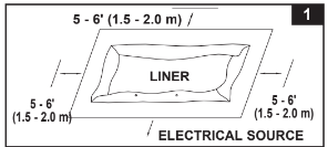
- Remove the ground cloth (14) from carton. Spread it out completely with its edges being at least 5 - 6’ m) from any obstacle such as walls, fences, trees, etc. Remove the liner (15) from carton and spread it out over the ground cloth with the drain valve towards the draining area. Place the drain valve away from the house. Open it up to warm it in the sun. This warming will make installation easier. Make sure the liner is centered atop the ground cloth. Be sure to face the end with the 2 hose connectors towards the electrical power source. IMPORTANT: Do not drag the liner across the ground as this can cause liner damage and pool leakage (see drawing 1).
- During the set-up of this pool liner, point the hose connections or openings in the direction of the electric power source. The outer edge of the assembled pool is to be within reach of the electrical connection for the optional filter pump.
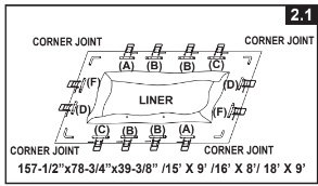
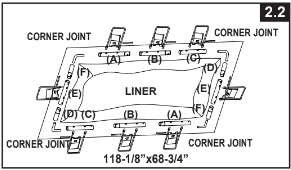
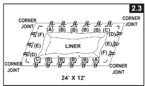
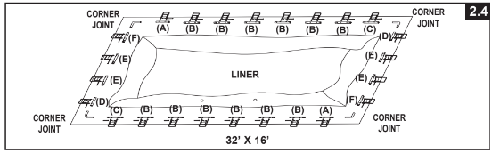
2. Remove all the parts from the carton(s) and place them on the ground in the location where they are to be assembled. Check the parts listing and be sure all the pieces to be assembled are accounted for see drawings 2.1-2.4).
IMPORTANT: Do not start assembly if any pieces are missing. For replacement pieces call the Consumer Service telephone number in your area. After all pieces are accounted for move the pieces away from the liner for of installation.
NOTE: Sprinkle some talcum powder over the horizontal beams before sliding them into the pool liner sleeve. This will make removal of the beams from the liner easier during the disassembly of the pool.
3. Be sure the liner is opened and spread out to its fullest extent on top of the ground cloth. Starting with one side, slide the “A” beams first into the sleeve openings located in each corner. Continue with “B” beam snapping into the “A” beam, and another “C” beam snapping into the “B” beam see drawing 3).
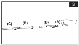
Keep the metal beam holes aligned with the white liner sleeve holes.
Continue inserting all “A-B-C & D-E-F” beams into the sleeve openings. Start the "D-E-F" combination for pool's short sides by inserting the "D" beam first into the opening.
The combinations for beams are different for different sizes of pools, see the chart below for detail. (Be sure all 4 sides end up with the metal beam holes aligned with the white liner sleeve holes.)
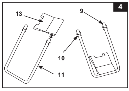
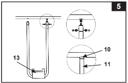
4. Slide the restrainer strap (13) onto the large U-shaped side support (11). Repeat for all restrainer straps and U-supports.
IMPORTANT: The liner is to remain flat on the ground during the next step #5. This is why 5 - 6’ of clearance space around the pool is necessary (see drawing 4).
5. The tops of the U-shaped side supports have a double button spring loaded clip (10) that is factory pre-installed.
Insert the side supports into the “A-B-C & D-E-F” beam holes by squeezing the bottom button inward with your fingers.
Squeezing this bottom button will allow the support to enter the beam. Once the U-support is inside the beam release the finger pressure allowing the support to “SNAP” into place. Repeat this procedure for all U-shaped side supports see drawing 5).
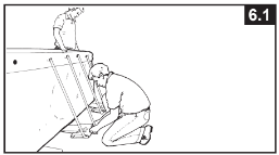
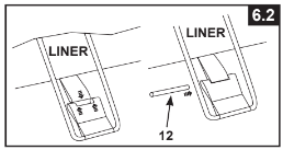
6. With one person standing inside the pool, raise one corner; insert the connecting rod (12) into the overlapping openings, to connect the liner straps to the restrainer straps. Repeat the operation in the other corners and then on the sides (see drawings 6.1 & 6.2).
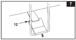
7. Pull the bottoms of the side supports out away from the liner to make the straps taut. Repeat for all locations (see drawing 7).
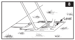
8. If the ground is not concrete (asphalt, lawn or earth) you must place a piece of pressure-treated wood, size x 15” x 1.2”, under each leg and set flush with the ground. The U-shaped side supports must be placed in the center of the pressure-treated wood and with the wood grain perpendicular to the support leg (see drawing 8).
NOTE: Make sure each support pad is recessed and set flush with the ground and not just placed on the ground. Do not use support pads or slabs with slippery, smooth surfaces as the U-shaped side support will slide outward causing damage to the pool and void the warranty.
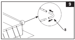
9. Position the long wall top rails so they are leaning over the short wall top rails. Installe the corner joints (8) at the corners (see drawing 9).
IMPORTANT: The four corner joints are designed to be moveable relative to the horizontal beams and not fixed to the horizontal beams. This allows the pool side walls to move inward or outward when the pool is in use.
10. Assemble the ladder. The ladder has separate assembly instructions in the ladder box.
11. Place the assembled ladder over one of the sides with one of the liner installation team members entering the pool to smooth out all bottom liner wrinkles. While inside the pool this team member should check the 2 drain valves (in corners) to be sure the inside drain plug is inserted into the valve. This team member should push each inside corner in an outward direction.
12. Before filling the pool with water, ensure that the drain plug inside the pool is closed and that the drain cap on the outside is screwed on tightly. Fill the pool with no more than 1 inch (2.5 cm) of water. Check to see whether the water is level.
IMPORTANT: If the water in the pool flows to one side, the pool is not completely level. Setting up the pool on unleveled ground will cause the pool to tilt resulting in the sidewall material to bulge. If the pool is not completely level, you must drain the pool, level the area and re-fill the pool.
Smooth out the remaining wrinkles (from inside pool) by pushing out where the pool floor and pool sides meet. Or (from outside pool) reach under the side of the pool, grasp the pool floor and pull it out. If the ground cloth is causing the wrinkles, have 2 people pull from either side to remove all wrinkles.
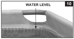
13. Fill the pool with water up to just below the sleeve line. (see drawing 10).
NOTE: The pool side walls and frame structure will lean inward after having been filled with water to the recommended level. Do not be concerned by the inward leaning of the side walls, this is to accommodate the water movement and pressure when the pool is in use.
14. Posting aquatic safety signs
Select a highly visible area near the pool to post the Danger No Diving or Jumping sign included later in this manual.
IMPORTANT: Before allowing anyone to use the pool, hold a family meeting. Establish a set of rules that include, at a minimum, the important safety rules and general aquatic safety information in this manual. Review these rules on a regular basis and with all users of the pool, including guests.
POOL MAINTENANCE & CHEMICALS
WARNING:
REMEMBER TO
- Protect all pool occupants from possible water-related illnesses by keeping the pool water clean and sanitized. Do not swallow the pool water. Always practice good hygiene.
- Keep your pool clean and clear. The pool floor must be visible at all times from the outside barrier of the pool.
- Keep children away from pool covers to avoid entanglement, drowning, or other serious injury.
Water maintenance
The maintenance of a proper water balance through appropriate use of sanitizers is the single most important factor in maximizing the life and appearance of the liner as well as ensuring clean, healthy and safe water. Proper technique is important for water testing and treating the pool water. See your pool professional for chemical, test kits and testing procedures. Be sure to read and follow the written instructions from the chemical manufacturer.
- Never let chlorine come into contact with the liner if it is not completely dissolved. Dissolve granular or tablet chlorine first in a bucket of water, then add it to the pool water. Likewise with liquid chlorine; mix it immediately and thoroughly with the pool water.
- Never mix chemicals together. Add the chemicals to the pool water separately. Thoroughly dissolve each chemical before adding another one to the water.
- An Intex pool skimmer and an Intex pool vacuum are available to assist in maintaining clean pool water. See your pool dealer for these pool accessories.
- Do not use a pressure washer to clean the pool.
CAUTION: ALWAYS FOLLOW THE CHEMICAL MANUFACTURER'S DIRECTIONS, AND THE HEALTH AND HAZARD WARNINGS.
Do not add chemicals if the pool is occupied. This can cause skin or eye irritation. Concentrated chlorine solutions can damage the pool liner. In no event is Intex Recreation Corp., Intex Development Co. Ltd., their related companies, authorized agents and service centers, retailers or employees liable to the buyer or any other party for costs associated with the loss of pool water, chemicals or water damage.
Keep spare filter cartridges on hand. Replace cartridges every two weeks. We recommend the use of a Krystal ClearTM Intex Filter Pump with all of our above-ground-pools. To purchase an Intex Filter Pump or other accessories see your local retailer, visit our website or call the Intex Consumer Services Department listed in the separate "Authorized Service Centers" sheet and have your Visa or Mastercard ready.
EXCESSIVE RAIN: To avoid damage to the pool and over filling, immediately drain rain water that causes the water level to be higher than the maximum.
How to Drain Your Pool and Long Term Storage
NOTE: This pool has drain valves installed in 2 corners. Connect the garden hose to the corner valve that directs the water to the appropriate location.
- Check local regulations for specific directions regarding disposal of swimming pool water.
- Check to make sure that the drain plug inside the pool is plugged in place.
- Remove the cap from the drain valve on the outside pool wall.
- Attach the female end of the garden hose to the drain connector (16).
- Place the other end of the hose in an area where the water can be safely drained away from the house and other nearby structures.
- Attach the drain connector to the drain valve. NOTE: The drain connector will push the drain plug open inside the pool and water will start to drain immediately.
- When the water stops draining, start lifting the pool from the side opposite the drain, leading any remaining water to the drain and emptying the pool completely.
- Disconnect hose and adapter when finished.
- Re-insert drain plug in drain valve on inside of pool for storage.
- Replace drain cap on outside of pool.
- Reverse the set-up instructions to disassemble the pool, and remove all connecting parts.
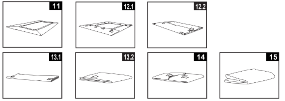
- Be sure that the pool and all parts are completely dry before storage. Air dry the liner in the sun until completely dry before folding (see drawing 11). Sprinkle some talcum powder to prevent vinyl from sticking together and to absorb any residual moisture.
- Create rectangular shape. Starting at one side, fold one-sixth of liner in on itself twice. Do the same on the opposite side (see drawings 12.1 & 12.2).
- Once you have created two opposing folded sides, simply fold one over the other like closing a book see drawings 13.1 & 13.2).
- Fold the two long ends to the middle (see drawing 14).
- Fold one over the other like closing a book and finally compact the liner (see drawing 15).
- Store the liner and accessories in a dry, temperature controlled, between 32 degrees Fahrenheit (0 degrees Celsius) and 104 degrees Fahrenheit (40 degrees Celsius), storage location.
- The original packing can be used for storage.
WINTER PREPARATIONS
Winterizing your Above Ground Pool
After usage, you can easily empty and store away your pool in a safe place. You must drain, disassemble and properly store the pool when the temperature drops below 41 degrees Fahrenheit (5 degrees Celsius) to prevent ice damage to the pool and related components. Ice damage can result in sudden liner failure or pool collapse. Also see the section “How To Drain Your Pool”.
Should temperatures in your area not drop below 41 degrees Fahrenheit (5 degrees Celsius), and you choose to leave your pool out, prepare it as follows:
- Clean the pool water thoroughly. If the type is an Easy Set Pool or an Oval Frame Pool, make sure that the top ring is properly inflated.
- Remove the skimmer (if applicable) or any accessories attached to the threaded strainer connector. Replace strainer grid if necessary. Be sure all accessories parts are clean and completely dry before storage.
- Plug the Inlet and Outlet fitting from the inside of the pool with the plug provided sizes 16' and below). Close the Inlet and Outlet Plunger Valve (sizes 17' and above).
- Remove the ladder (if applicable) and store in a safe place. Be sure the ladder is completely dry before storage.
- Remove the hoses that connect the pump and filter to the pool.
- Add the appropriate chemicals for the winter period. Consult your local pool dealer as to which chemicals you should use and how to use them. This can vary greatly by region.
- Cover pool with Intex Pool Cover. IMPORTANT NOTE: INTEX POOL COVER IS NOT A SAFETY COVER.
- Clean and drain the pump, filter housing and hoses. Remove and discard the old filter cartridge. Keep a spare cartridge for the next season.
- Bring pump and filter parts indoors and store in a safe and dry area, preferably between 32 degrees Fahrenheit (0 degrees Celsius) and 104 degrees Fahrenheit (40 degrees Celsius).
TROUBLESHOOTING
ALGAE
- Greenish water.
- Green or black spots on pool liner.
- Pool liner is slippery and/or has a bad odor.
- Chlorine and pH level need adjustment.
- Super chlorinate with shock treatment. Correct pH to your pool store’s recommended level.
- Vacuum pool bottom.
- Maintain proper chlorine level.
COLORED WATER
- Water turns blue, brown, or black when first treated with chlorine.
- Copper, iron or manganese in water being oxidized by the added chlorine.
- Adjust pH to recommended level.
- Run filter until water is clear.
- Replace cartridge frequently.
FLOATING MATTER IN WATER
- Water is cloudy or milky.
- "Hard water” caused by a too high pH level.
- Chlorine content is low.
- Foreign matter in water.
- Correct the pH level. Check with your pool dealer for advice.
- Check for proper chlorine level.
- Clean or replace your filter cartridge.
CHRONIC LOW WATER LEVEL
- Level is lower than on previous day.
- Rip or hole in pool liner or hoses.
- Repair with patch kit.
- Finger tighten all caps.
- Replace the hoses.
SEDIMENT ON POOL BOTTOM
- Dirt or sand on pool floor.
- Heavy use, getting in and out of pool.
- Use Intex pool vacuum to clean bottom of pool.
SURFACE DEBRIS
POOL INLET AIR ADAPTOR LEAKING
- Hose clamps are not well-fitted.
- Tighten or reinstall hose clamps.
INLET TREADED AIR CONNECTOR LEAKING
- Plunger valve not well-fitted.
- Tighten or reinstall plunger valve.
AIR JET VALVE LEAKING
- Air jet valve is not tight and facing up.
- Tighten air jet valve and make sure it’s facing up.
- Air jet valve internal seal blocked.
- Turn ON or plug in the pump and run for few seconds, then turn OFF or unplug, repeat 3 times.
- Air jet valve internal seal dirty.
- Remove air jet valve, flush dirt out with water and replace valve back.
- Air jet valve broken.
- Replace a new air jet valve.