User manual Saltwater System
SETUP INSTRUCTIONS
1. Assemble the above-ground-pool (AGP) and its filter pump according to their installation instructions.
2. Take the Saltwater System and its accessories out of the packaging.
3. Place the Saltwater System in line after the filter pump.
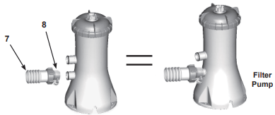
4. Connect the connector hose (7) to the Saltwater System inlet.
Connecting the system to pump and pool with 1-1/4” (32mm) connections/ hoses:
The saltwater system features 1-1/2” (38mm) connections. It is accordingly supplied with adaptors A (1) and B (8) for connecting to the small 1-1/4” (32mm) diameter connections/hoses. Install as follows:
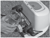
Drawing #1
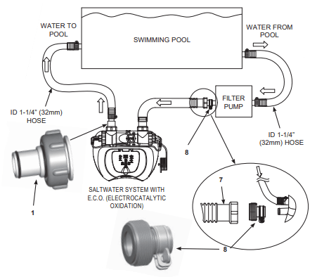
1. Go directly to step 2 if your pool is empty. If your above-ground-pool is filled with water, unscrew the strainer grids from the strainer connectors and insert the black hat-like plugs into the connectors, before installing the saltwater pool system.
2. Connect the adaptor A (1) to the electrolytic cell (3) outlet as shown in Drawing #1. Tighten securely
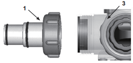
3. Disconnect the water return hose from the filter pump connection and connect it to the adaptor A (1) on the Saltwater System with a hose clamp. (see Drawing #1)
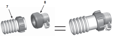
4. Connect adaptor B (8) to the connector hose (7). Tighten securely. (see Drawing #1)
5. Connect adaptor B (8) to filter pump outlet (lower connection). Tighten securely.
6. Remove the black hat-like plugs that prevent water from flowing out of the pool. Now, return the strainer grids to the strainer connectors.
Connecting the system to pump and pool with 1-1/2” (38mm) connections/hoses: Pump and pool with 1-1/2” (38mm) connections do not require the adaptors A (1) or B (8). Install as follows:
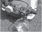
Drawing #2
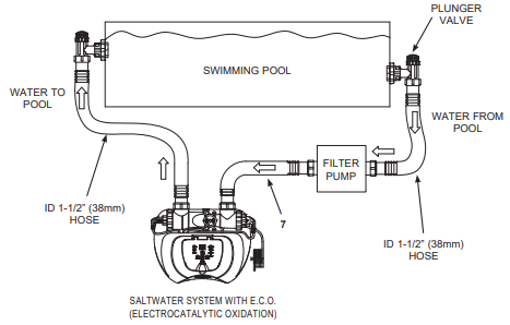
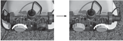
1. Go directly to step 2 if your pool is empty. If your above-ground-pool is filled with water, close the plunger valves before installing the Saltwater System.
2. Disconnect the water return hose from the filter pump connection and connect it to the Saltwater System outlet.
3. Connect the connector hose (7) to the filter pump outlet connection.
4. Open the plunger valves to allow the water to flow.
Connecting the system to other types of pump (with different type of thread or no thread):
The Saltwater System can also be adapted to other filter pumps with different thread or those without a thread on the connection.
Connection to 1-1/4” (32mm) hose:
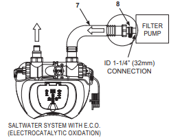
1. Connect one end of adaptor B (8) to the connector hose (7). Tighten securely.
2. Now, connect the other end of adaptor B (8) to the filter pump outlet. Tighten securely.
Connection to 1-1/2” (38mm) hose with clamp:
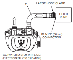
1. Connect the connector hose (7) to the filter pump outlet connection with a large hose clamp. Tighten securely.
Connecting the system to other types of pool
After you have connected the Saltwater System to the pump, connect it to the pool.
This is depicted in Drawings #1 and #2.
Following are the common connection types:
Connection to 1-1/4” (32mm) connectors:
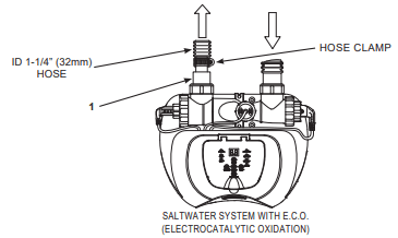
1. Connect the adaptor A (1) to the electrolytic cell (3) outlet. Tighten securely.
2. The adapter A (1) is now fitted to the Saltwater System. The following step is to connect the water return hose to the adaptor A (1) with a hose clamp.
Connection to 1-1/2” (38mm) connectors without thread:
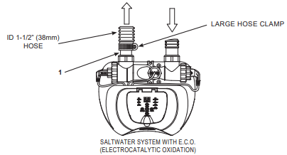
1. Connect the adaptor A (1) to the electrolytic cell (3) outlet. Tighten securely.
2. With the adaptor A (1) fixed to the Saltwater System, connect the water return hose to the adaptor, using a large hose clamp.
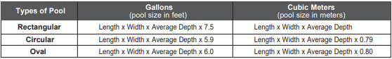
SALT & POOL WATER VOLUMES
Which kind of salt to use:
Use only Sodium Chloride Salts
Use only sodium chloride (NaCl) salt that is at least 99.8% pure. It is also acceptable to use water conditioning salt pellets (the compressed forms of evaporated salt). However, it will take a longer time for them to dissolve.
Do not use iodized or yellow (yellow prussiate of soda) colored salt.
Salt is added to the pool water and the electrolytic cell uses the salt to create chlorine. The purer the salt the better the performance of the electrolytic cell.
Optimum Salt Levels
The ideal salt level in the pool water is between 2500-3500 ppm (parts per million). The optimal level is 3000 ppm.
A too low salt level will reduce the efficiency of the Saltwater System and result in low chlorine production. A high salt level may generate a salty taste to the pool water (this may occur at a salt level above 3500-4000ppm). Too high a salt level may damage the power supply and cause corrosion to the pool metal fixtures and accessories. The Salt Table page of this manual, shows the correct dosage of salt needed. The salt in the pool is constantly recycled. The loss of salt is due only to pool water being physically removed from the pool. Salt is not lost due to evaporation.
Adding Salt
- Switch the filter pump on to start the water circulation.
- Keep the Saltwater System turned off.
- Determine the amount of salt to be added (see “Salt Table”).
- Evenly spread the proper amount of salt around the inside perimeter of the pool.
- Avoid clogging the filter. Do not add salt through the skimmer.
- Brush the pool bottom to speed up the dissolving process. Do not allow salt to pile up on the bottom of the pool. Run the filter pump 24 consecutive hours to thoroughly dissolve the salt.
- After 24 hours and if all the salt is dissolved, turn on the Saltwater System, press
 button until you hear a “beep”, code “00” flashing and set the saltwater pool system to desired operating time (see “Operating Time Table”).
Removing Salt
If too much salt has been added, the unit will beep and display “Code 92” (see “Alarm Codes”). You will need to lower the salt concentration. The only way to do so, is to partially drain the pool and refill it with fresh water. Drain and refill approximately 20% of the pool’s water until the “Code 92” disappears.
Pool Volume Calculation
OPERATION INSTRUCTIONS
1. Turn on the filter pump.
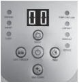
2. Start up the unit:
Plug the power cord into the electrical outlet and test the GFCI/RCD (circuit breaker). Press  button. Flashing code “00” appears on the electronic control station’s LED, indicating that the unit is ready to be programmed.
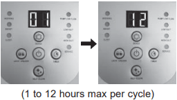
3. Set operating hours for Saltwater system:
With code “00” flashing, press  button to set the desired operating hours. See the “Operating Time Table” for the required operating hours related to each pool size. Pressing will increase the time from 01 to 12 hours maximum. If you have selected too many hours keep pressing to repeat the cycle. The built-in timer will now activate your Saltwater System, at the same time each day, for the number of hours you have set.
NOTE: The Saltwater System will not operate if the filter pump is not operating. Make sure to program your filter pump (or start it manually) for operation beginning 5 minutes before the saltwater system and finishing 15 minutes after the saltwater system.
4. Lock keypad controls:
With the desired hour value showing, press button until you hear a “beep”. A green “WORKING” indicator on the control panel will light up within a few seconds to indicate that the saltwater system has started chlorine production. Locking the control buttons into this setting prevents unauthorized changing of the operating cycle.
NOTE: If you forget to lock the keypad controls, the system will automatically lock it and start working 1 minute later.
5. Readjust operating time if necessary:
The operating hours can be re-adjusted if necessary. Press button until you hear a “beep” to unlock the keypad and the current programmed time will flash. Repeat steps 3 to 4.
6. Boost cycle
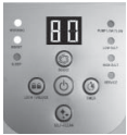
First time installation, press and hold “BOOST” button for 5 seconds until the indicator lights up and the LED display “80”. This indicates that the saltwater system has started E.C.O. and more chlorine sanitizer production. You can press and hold the “BOOST” button for another 5 seconds until the indicator is off, which will cancel the Boost cycle.
The boost operating hours is 8 times the amount of time programmed into the system, i.e. if your saltwater system operating time is 2 hours, the boost procedure will run 8 x 2 = 16 hours. After boost procedure has been completed, the system will automatically switch to the normal working mode.
Once the boost is operating, check whether the filter pump operating hours have been set properly. For example, the boost operating time is 8 hours, the filter pump should be set to run for 8 hours at least. Increase the filter pump operating time if necessary. Note: If an Intex filter pump is attached to the system, set the pump switch to on “I” position.
After a heavy rain or if the pool is dirty, press the “BOOST” button to shock the pool again.
7. Stand-by/power saving mode:
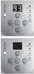
When the cycle ends, the green “SLEEP” indicator on the control panel lights up and the LED display flashes “93”. The system is now in Stand-By mode. After a while, it shuts down and sets itself in a Power Saving mode. The system will automatically turn itself back on in 24 hours, starting its daily cycle of chlorine production.
The “SLEEP” indicator stays on, while the system is in the Power Saving mode. The LED display however, goes blank after 5 minutes. Press any button ( or ) to view the last LED code.
8. Electrode Self-Clean cycle:
- Press and hold
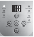
 button for 5 seconds until the LED display flashes “10”. Depending on your pool water calcium hardness level, press button again to select the self-clean cycle time as below. Total of 3 settings: 14 hours, 10 hours and 06 hours.
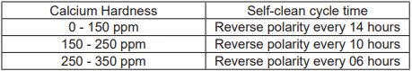
NOTE: The life of the cell varies depending on water conditions, pool usage and operating time of the device. Select 14 hours cycle time to maximize the life of the electrolytic cell if the calcium hardness level is up to 150 ppm. Manual routine cleaning and maintenance will further lengthen the life of the electrolytic cell.
With the desired self-clean hours showing, press button to lock the keypad controls and the LED display will return to the normal operating time. The system will reverse the polarity of the electrode (5) every time according to the selected hours. NOTE: If you forget to lock the keypad controls, the system will automatically lock it and start working 5 seconds later.
LED CODE CHART
80 Boost Mode
00 Stand-By Mode (Start-up)
01 Minimum Operating Hour (1 hour remaining)
02 Operating Hours (2 hours remaining)
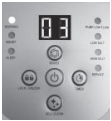
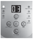
03 Operating Hours (3 hours remaining)
04 Operating Hours (4 hours remaining)
05 Operating Hours (5 hours remaining)
06 Operating Hours (6 hours remaining)
07 Operating Hours (7 hours remaining)
08 Operating Hours (8 hours remaining)
09 Operating Hours (9 hours remaining)
10 Operating Hours (10 hours remaining)
11 Operating Hours (11 hours remaining)
12 Maximum Operating Hours (12 hours remaining)
90 Alarm Code(Low Pump Flow/No Pump Flow)
91 Alarm Code (Low Salt Level)
92 Alarm Code (High Salt Level)
93 Stand-By Mode (Operating Process finished)
“BLANK” No Power or “Power Saving Mode” waiting to start next Saltwater System cycle.
MAINTENANCE
Flow Sensor Cleaning
1. In a counter-clockwise motion unscrew the collar of the flow sensor (6) and remove it from the electrolytic cell conduit. See “Part Reference”.
2. If deposits and debris are seen on the surface of the flow sensor, then use a garden hose to wash it off.
3. If flushing with water does not remove the deposits, use a plastic brush to clean the surface and the hinge if necessary. Do not use a metal brush.
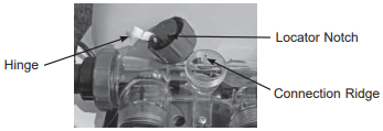
4. After the flow sensor has been inspected and cleaned, align the locator notch on the flow sensor to the connection ridge in the conduit. Now turn the collar in a clockwise motion, tightening the sensor back into its position. Do not overtighten.
Titanium and E.C.O. Electrodes Cleaning
The titanium electrode and E.C.O. electrodes have a self cleaning function incorporated into the electronic control’s programming. In most cases this self cleaning action will keep the electrodes working at optimum efficiency. If the pool water is hard (high mineral content) the electrodes may require periodic manual cleaning. To maintain maximum performance, we recommend that you open and visually inspect the titanium and E.C.O. electrodes (4 & 5) monthly.
The following steps provide instructions on how to clean your cell.
Inspection and cleaning:
1. Switch off the unit, unplug the power cord from the electrical socket.
2. For filter pumps with 1-1/4” (32mm) hose size - To prevent water from flowing out of the pool, unscrew the strainer grids from the strainer connectors and insert the hat-like plugs into the strainer connectors. For filter pumps with 1-1/2” (38mm) hose size - Turn both plunger valve handles fully clockwise until they stop. This closes the valve, prevents the water from flowing out of the pool.
3. Disconnect the 2 hoses from the Saltwater System, and attach the cell covers (9) to the inlet and outlet of the electrolytic cell (3).
4. Unscrew the collar of the flow sensor (6) and pull out the flow sensor from the electrolytic cell (3) housing.
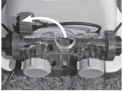
5. Pour kitchen grade vinegar into the electrolytic cell (3) to immerse the titanium and ECO electrodes. Soak for 1 hour.
6. Open one side of the cell cover (9), drain and properly dispose of the vinegar. Connect the hose which goes from the pool to the cell. Flush the electrolytic cell housing with the pool water.
7. Reverse steps 3, 4, 5 and 6 to reconnect the electrolytic cell.
INTEX® TEST STRIPS (PACKED WITH THE PRODUCT)
The Test Strips can test the “Free Chlorine”, “pH”, “Calcium Hardness” and “Total Alkalinity” levels at the same time. We recommend that you test the water chemistry weekly, and maintain the chlorine concentration at 0.5-3.0 ppm.
Directions and Use
1. Dip the entire strip into the water and remove immediately.
2. Hold the strip level for 15 seconds. Donot shake excess water from the strip.
3. Now compare the strip pad to the color chart on the packaging label. If necessary, adjust the chemical level in the pool water. It is very important, to use the proper technique when testing the water's chemical level. Read and follow the written strip instructions carefully.
LONG TERM STORAGE
1. Disconnect the power cord from the electrical outlet.
2. After the pool is completely empty, disconnect the Saltwater System from the hoses by reversing the installation instructions.
3. Air-dry the unit before you store it. This might be a good time to visually inspect and clean the electrolytic cell.
4. Store the unit and accessories in a dry place. The temperature should be controlled, between 32 degrees Fahrenheit (0 degrees Celsius) and 97 degrees Fahrenheit (36 degrees Celsius).
5. The original package can be used for storage.
TROUBLESHOOTING GUIDE
INSUFFICIENT CHLORINE
- Insufficient operating hours of the Saltwater System.
- The salt level in the pool water is less than 2000 ppm. This is insufficient.
- Chlorine loss due to intense sunlight exposure.
- The bather load has increased.
- Clogged or dirty electrolytic cell.
- High UV level exposure.
Increase the daily Saltwater System operating time. See “Operating Instructions”.
Check the salt level with the Test Kit. Adjust as needed. See “Salt & Pool Water Volumes”.
Use a pool cover when the pool is not in use and/or when the unit is operating.
Increase the daily Saltwater System operating time. See “Operating Instructions”.
Remove the cell for inspection, clean it if necessary. See “Maintenance”.
Cover the pool with a pool cover for 2 days with the device running and then test the water using the test strips.
If the pool is clean and clear, add stabilizer to the water and then test the water with the device running.
WHITE FLAKES IN THE WATER
- Excessive calcium hardness is present in pool water.
Drain about 20 to 25% of the pool water and add fresh water to decrease the calcium hardness. Inspect the electrolytic cell for scale buildup. Clean the electrolytic cell if necessary.
NO LED DISPLAY
- No power supply.
- RCD/GFCI has not reseted.
- A power fuse has blown.
- LED failure.
Find out the switch and turn on.
Reset the RCD/GFCI.
Contact Intex Service Center.
This device complies with part 15 of the FCC Rules. Operation is subject to the following two conditions: (1) This device may not cause harmful interference, and (2) this device must accept any interference received, including interference that may cause undesired operation.
WARNING: Changes or modifications not expressly approved by the party responsible for compliance could void the user’s authority to operate the equipment.
NOTE: This equipment has been tested and found to comply with the limits for a Class B digital device, pursuant to part 15 of the FCC Rules. These limits are designed to provide reasonable protection against harmful interference in a residential installation. This equipment generates, uses and can radiate radio frequency energy and, if not installed and used in accordance with the instructions, may cause harmful interference to radio communications. However, there is no guarantee that interference will not occur in a particular installation. If this equipment does cause harmful interference to radio or television reception, which can be determined by turning the equipment off and on, the user is encouraged to try to correct the interference by one or more of the following measures:
- Reorient or relocate the receiving antenna.
- Increase the separation between the equipment and the receiver.
- Connect the equipment into an outlet on a circuit different from that to which the receiver is connected.
- Consult the dealer or an experienced radio/TV technician for help.

1. Filter pump not attached to system and/or switch on.
Ensure filter pump is attached and operating. See "Setup Instruction".
2. Circulation line is blocked.
If your unit has plunger valves, ensure that they are open.
Clear your filter cartridge and cell from debris and dirt. See “Maintenance”.
Release all trapped air in the circulation line. See the filter pump manual.
3. Incorrect inlet and outlet hose direction.
Check the direction of the inlet and the outlet hose. Reverse the hoses if necessary. See “Set Up Instructions”.
4. Scale on the flow sensor.
Clean the flow sensor, paying special attention to the hinge. See “Maintenance”.
5. Flow sensor cord is loose.
Plug the flow sensor firmly into the flow sensor receptacle.
6. Inner timer conflict between filter pump and saltwater system.
Reset both timers on the filter pump and saltwater system. See “Boost Cycle”.
7. Flow sensor failure.
Contact Intex Service Center.

1. Dirt or scale on titanium plates.
Remove the electrolytic cell for inspection. Clean it if necessary. See “Maintenance”.
2. Low salt level / No salt.
Add salt. See “Salt & Pool Water Volumes”
3. Electrolytic cell cord is loose.
Ensure that the cell cord is plugged firmly into the cell housing receptacle.
4. Possible electrolytic cell failure.
Contact Intex Service Center. Replace the cell if needed.

1. High salt level.
2. Water temperature > 35ºC.
3. Titanium electrode failure.
Partially drain the pool and refill it with fresh water. See “Salt & Pool Water Volumes”.
Contact Intex Service Center.

1. LED display is off and the “SERVICE” light is on - the system does not power up.
2. Caused by high humidity.
3. PCB failure.
Household voltage is too high or too low (+ 20%). Check the voltage is within the range stated on the device housing.
Run the system during midday and avoid running it during dawn, foggy or raining time. Place a piece of tile or similar pad, 15”x15” (38x38 cm) in size, between the device and the ground to keep ground water evaporation away from the system.
Contact Intex Service Center.
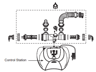
CONTROL STATION REPLACEMENT
Tools required: One (1) Phillips screwdriver
If only the control station (13) needs to be replaced as instructed by the service center, remove all the components inside the dotted frame and keep them in a safe place for later use.
Once you have received the new replacement control station, reinstall all the components from the previous unit to the new control station.