
341
PO
(341PO) MODEL SF90110-1 SAND FILTER PUMP ENGLISH 7.5” X 10.3” PANTONE 295U 06/13/2019
English
IMPORTANT
SAFETY RULES
Read, understand, and follow
all instructions carefully before
installing and using this product.
Don’t forget to try these other fine Intex products: pools, pool
accessories, inflatable pools and in-home toys, airbeds and boats
available at fine retailers or visit our website.
Due to a policy of continuous product improvement, Intex reserves
the right to change specifications and appearance, which may
result in updates to the instruction manual without notice.
OWNER’S MANUAL
IMPORTANT!
DO NOT RETURN PRODUCT TO STORE
To purchase parts and accessories or to obtain non-technical assistance, Visit
www.intexcorp.com
For technical assistance and missing parts call us toll-free (for U.S. and Canadian Residents):
1-800-234-6839
Monday through Friday, 8:30am to 5:00pm Pacific Time
341-*PO-R0-2006
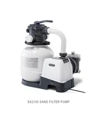
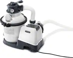
Krystal Clear
TM
Sand Filter Pump
Model SF90110-1
For illustrative purposes only.
341
PO
SAVE THESE INSTRUCTIONS
(341PO) MODEL SF90110-1 SAND FILTER PUMP ENGLISH 7.5” X 10.3” PANTONE 295U 06/13/2019
English
Page 2
Warnings
....................................................................................................
3
Parts References
.......................................................................................
4-6
Setup Instructions
....................................................................................
7-14
Product Specifications
..............................................................................
9
Operating Instructions
.............................................................................
15-17
Intex Pools Operating Time Table
............................................................
18
Non-Intex Pools Operating Time Table
....................................................
19
Maintenance
...............................................................................................
20
Long Term Storage
....................................................................................
20
Troubleshooting Guide
.............................................................................
21
Common Pool Problems
...........................................................................
22
General Aquatic Safety
.............................................................................
23
Limited Warranty
........................................................................................
24
TABLE OF CONTENTS
341
PO
SAVE THESE INSTRUCTIONS
(341PO) MODEL SF90110-1 SAND FILTER PUMP ENGLISH 7.5” X 10.3” PANTONE 295U 06/13/2019
English
Page 3
IMPORTANT SAFETY RULES
Read, Understand and Follow All Instructions Carefully Before Installing and Using this Product.
READ AND FOLLOW ALL INSTRUCTIONS
WARNING
•
To reduce the risk of injury, do not permit children to use this product. Always supervise children
and those with disabilities.
•
Children must stay away from this product and electrical cord(s).
•
Assembly and disassembly by adults only.
•
Risk of electric shock. Connect only to a grounding type receptacle, this product is provided with
a ground-fault circuit interrupter. If replacement of the plug or cord is needed, use only identical
replacement parts.
•
Always unplug this product from the electrical outlet before removing, cleaning, servicing or
making any adjustment to the product.
• The unit is provided with a ground-fault circuit interrupter (GFCI). To test the GFCI, push the test
button. The GFCI should interrupt power. Push the reset button, power should be restored. If the
GFCI fails to operate in this manner. The GFCI is defective. If the GFCI interrupts power to the
pump without the test button being pushed, a ground current is flowing, indicating the possibility
of an electric shock. Do not use this pump. Disconnect the pump and have the problem corrected
by a qualified service representative before using.
•
Do not bury the electrical cord. Locate the cord where it will not be damaged by lawn mowers,
hedge trimmers and other equipment.
•
To reduce the risk of electric shock, replace damaged cord immediately. Use a qualified
electrician to replace the cord.
•
To reduce the risk of electric shock, do not use extension cords, timers, plug adaptors or
converter plugs to connect unit to electric supply; provide a properly located outlet.
•
Do not attempt to plug in or unplug this product while standing in water or when your hands are
wet.
•
Do not use an appliance leakage current interrupter (ALCI) in place of a GFCI since the ALCI will
protect people.
• Position this product away from pool, so as to prevent children from climbing on it and access the
pool.
• Make sure the electrical parameters indicated on the product correspond to the local mains
voltage before you connect the unit.
•
To reduce the risk of entrapment hazard, never enter the pool if suction strainer component is
loose, broken, cracked, damaged or missing. Replace loose, broken, damaged, cracked or
missing suction strainer components immediately.
• Never play or swim near suction fittings. Your body or hair may be trapped causing permanent
injury or drowning.
• To prevent equipment damage and risk of injury, always turn pump off before changing the filter
control valve position.
• Never operate this product above the maximum working pressure stated on the filter tank.
• Hazardous Pressure. Improper tank valve cover assembly could cause the valve cover to blow
off and cause serious injury, property damage or death.
• This product is intended to be used only for the purposes described in the manual!
FAILURE TO FOLLOW THESE WARNINGS MAY RESULT IN PROPERTY
DAMAGE, ELECTRIC SHOCK, ENTANGLEMENT OR OTHER SERIOUS
INJURY OR DEATH.
This product is for use with storable pools only. Do not use with permanently-installed pools. A storable pool
is constructed so that it is capable of being readily disassembled for storage and reassembled to its original
integrity. A permanently-installed pool is constructed in or on the ground or in a building such that it cannot be
readily disassembled for storage.
To reduce the risk of electric shock the pool must be installed no closer than 6 feet (1.8 m) from any electrical
outlet. Do not place portable appliances closer than 5 feet (1.5 m) from the pool.
These product warnings, instructions and safety rules provided with the product represent some common
risks of water recreation devices and do not cover all instances of risk and danger. Please use common
sense and good judgement when enjoying any water activity.
CAUTION
341
PO
SAVE THESE INSTRUCTIONS
(341PO) MODEL SF90110-1 SAND FILTER PUMP ENGLISH 7.5” X 10.3” PANTONE 295U 06/13/2019
English
Page 4
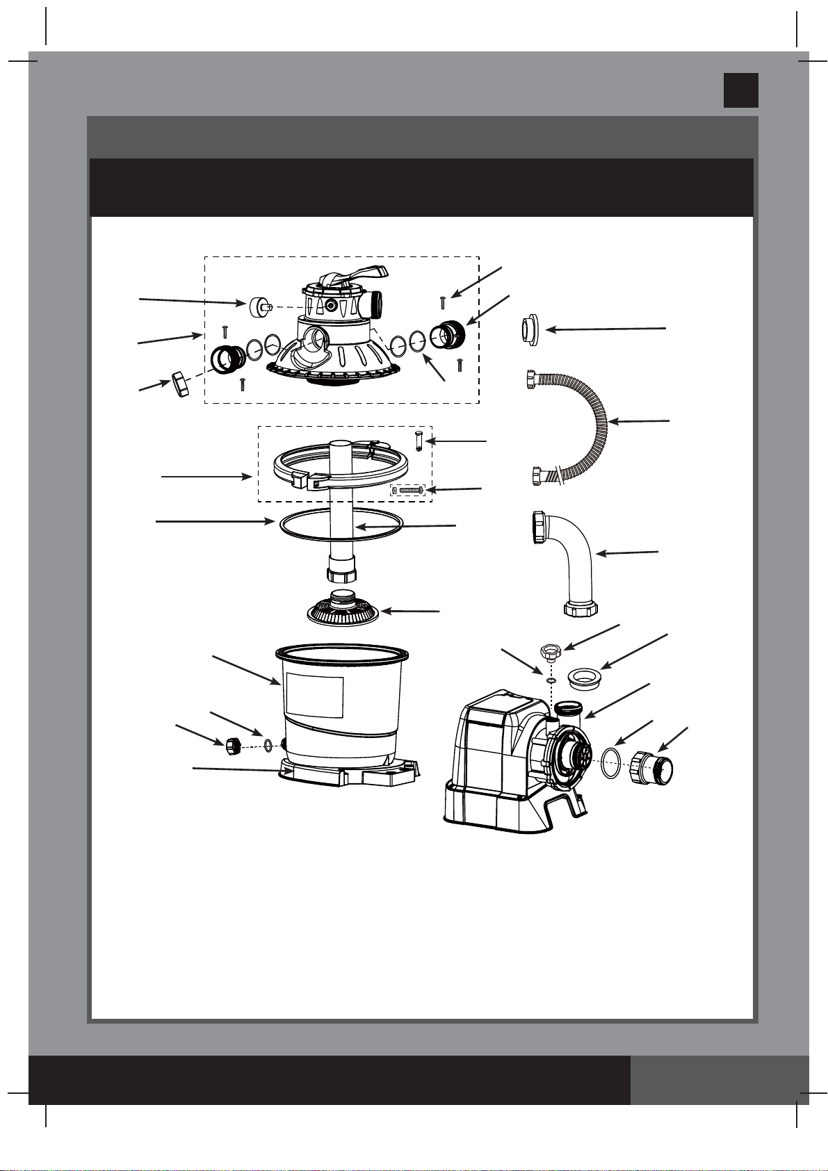
PARTS REFERENCE
Before assembling your product, please take a few minutes to check the contents
and become familiar with all the parts.
NOTE:
Drawings for illustration purpose only. Actual product may vary. Not to scale.
1
14
9
6
2
13
20
35
36
3
15
16
4
12
7
8
32
11
33
17
10
5
19
34
18
341
PO
SAVE THESE INSTRUCTIONS
(341PO) MODEL SF90110-1 SAND FILTER PUMP ENGLISH 7.5” X 10.3” PANTONE 295U 06/13/2019
English
Page 5
PARTS REFERENCE
Before assembling your product, please take a few minutes to check the contents
and become familiar with all the parts.
*
If this pump was not purchased as part of a pool set, the above
parts can be ordered at www.intexcorp.com if needed.
Parts shown on this page are supplied with the pool package and
are shown here for assembly purposes only.
This device complies with part 15 of the FCC Rules. Operation is subject to the following two
conditions: (1) This device may not cause harmful interference, and (2) this device must accept
any interference received, including interference that may cause undesired operation.
WARNING:
Changes or modifications not expressly approved by the party responsible for
compliance could void the user’s authority to operate the equipment.
NOTE:
This equipment has been tested and found to comply with the limits for a Class B digital
device, pursuant to part 15 of the FCC Rules. These limits are designed to provide reasonable
protection against harmful interference in a residential installation. This equipment generates,
uses and can radiate radio frequency energy and, if not installed and used in accordance with
the instructions, may cause harmful interference to radio communications. However, there is no
guarantee that interference will not occur in a particular installation. If this equipment does cause
harmful interference to radio or television reception, which can be determined by turning the
equipment off and on, the user is encouraged to try to correct the interference by one or more of
the following measures:
•
Reorient or relocate the receiving antenna.
•
Increase the separation between the equipment and the receiver.
•
Connect the equipment into an outlet on a circuit different from that to which the receiver is
connected.
•
Consult the dealer or an experienced radio/TV technician for help.
NOTE:
Drawings for illustration purpose only. Actual product may vary. Not to scale.
No tools are required for the assembly.
21
22
23
24
25 38
27
21
22
23 24
25
26
28
40
30
28
29
31
**
**
37
37
39
42
341
PO
SAVE THESE INSTRUCTIONS
(341PO) MODEL SF90110-1 SAND FILTER PUMP ENGLISH 7.5” X 10.3” PANTONE 295U 06/13/2019
English
REF. NO. DESCRIPTION QTY. SPARE PART NO.
1 PRESSURE GAUGE 1 11720
2 TANK COVER & 6-WAY VALVE SET 1 11721B
3 DRAIN OUTLET COVER 1 11131
4 CLAMP ASSEMBLY 1 11722
5 TANK O-RING 1 11728
6 SAND FILTER PUMP MOTOR INLET O-RING 1 10712
7 CENTER PIPE 1 11729
8 FILTER GRID 1 11730
9 DRAIN VALVE CAP 1 11456
10 DRAIN VALVE O-RING 1 11385
11 L-SHAPE O-RING 4 11228
12 HOSE WITH NUTS 2 11009
13 SAND FILTER INTERCONNECETING HOSE 1 11763
14 TRANSPARENT OUTLET ADAPTOR 2 11723
15 TRANSPARENT OUTLET ADAPTOR O-RING 4 11724
16 CLAMP PIN 1 11726
17 CLAMP SCREW 1 11727
18 L-SHAPE O-RING 1 11412
19 TRANSPARENT LEAF TRAP 1 11733
20 PUMP MOTOR 1 12703
21*
PLUNGER VALVE (HOSE O-RING & STEP WASHER INCLUDED)
2 10747
22*
HOSE O-RING
2 10262
23* STEP WASHER 2 10745
24* STRAINER NUT 2 10256
25* FLAT STRAINER RUBBER WASHER 2 10255
26* THREADED STRAINER CONNECTOR 1 10744
27* ADJUSTABLE POOL INLET JET NOZZLE 1 12369
28* ADAPTOR B 2 10722
29* STRAINER CONNECTOR 1 11070
30* POOL INLET JET NOZZLE 1 12364
31* STRAINER GRID 1 11072
32 10" SAND FILTER PUMP TANK 1 12711
33 10" SAND FILTER PUMP TANK BASE 1 12715
34 TRANSPARENT OUTLET ADAPTOR SCREW 4 11725
35 AIR RELEASE VALVE 1 10725
36 VALVE
O-RING
1 10264
37* AIR JET VALVE 1 12363
38* INLET THREADED AIR CONNECTOR 1 12371
39* POOL INLET AIR ADAPTOR 1 12368
40* INLET STRAINER CONNECTOR 1 12365
41* AIR JET VALVE CAP (NOT SHOWN) 1 12373
42* STRAINER GRID 1 10253
PARTS REFERENCE (continued)
Before assembling your product, please take a few minutes to check the contents and become familiar with all the parts.
Page 6
* If this pump was not purchased as part of a pool set, the above parts can be ordered at
www.intexcorp.com if needed.
When ordering parts, be sure to quote the model number and part numbers.
341
PO
SAVE THESE INSTRUCTIONS
(341PO) MODEL SF90110-1 SAND FILTER PUMP ENGLISH 7.5” X 10.3” PANTONE 295U 06/13/2019
English
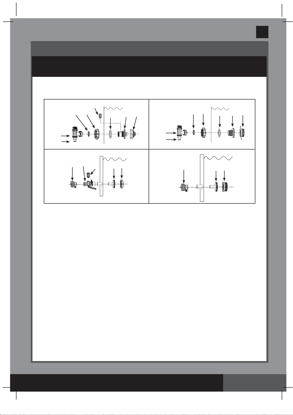
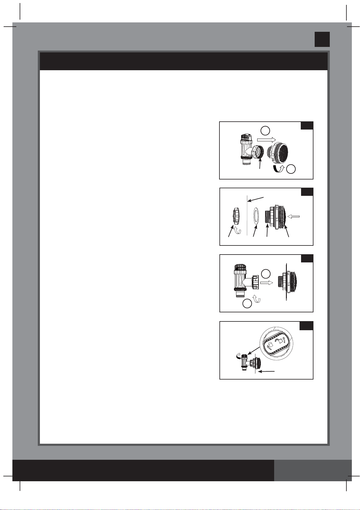
POOL OUTLET - STRAINER & PLUNGER VALVE SETUP (OPTIONAL)
Page 7
The strainer grid prevents large objects from jamming and/or damaging the filter pump. If
your pool has an inflatable top ring, install the strainer, nozzle and plunger valve before
inflating the pool liner top ring. The part numbers here onward refer to the parts depicted
in the Parts List section of this manual. To install, do the following:
1.
In a counter-clockwise motion unscrew plunger valve
union from the threaded strainer connector
(26)
(see
drawing 1)
. Be careful not to lose the step rubber
washer
(23)
. Place the plunger valve on the ground
in a safe place.
2.
In a counter-clockwise motion unscrew the strainer
nut
(24)
from the threaded connector
(26).
Leave the
flat washer
(25)
on the connector
(26)
.
3.
Install the strainer and plunger valve at the lower
position of pool outlet (marked "+").
From the inside
of the pool liner insert the connector
(26)
into one of
the pre-cut holes with the washer remaining on the
connector to be placed against the inside of the liner
wall.
4.
Before assembly, lubricate the threads with a
petroleum jelly. With the flat side of the strainer nut
(24)
facing the outside wall of the liner in a clockwise
motion screw the strainer nut
(24)
back onto the
threaded connector
(26) (see drawing 2)
.
5.
Finger tighten the strainer nut
(24)
onto the threaded
connector
(26)
.
6.
Grasp the plunger valve assembly. Make sure the
step washer
(23)
is in place.
7.
In a clockwise motion screw the plunger valve union
back onto the threaded connector
(26) (see
drawing 3)
.
8.
In a clockwise motion turn the plunger valve handle
to close position. Ensure the plunger valve is
securely closed. This will prevent water from flowing
out during filling of the pool
(see drawing 4)
.
2
25
26
INSIDE
LINER WALL
24
1
23
2
1
3
1
2
4
INSIDE
LINER WALL
42
341
PO
SAVE THESE INSTRUCTIONS
(341PO) MODEL SF90110-1 SAND FILTER PUMP ENGLISH 7.5” X 10.3” PANTONE 295U 06/13/2019
English
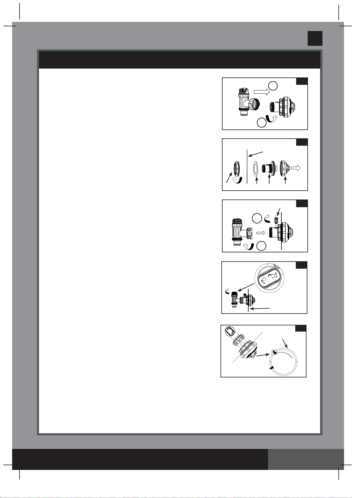
POOL INLET - NOZZLE & PLUNGER VALVE SETUP (OPTIONAL)
Page 8
1.
In a counter-clockwise motion unscrew plunger valve
union from the inlet threaded air connector
(38)
(see
drawing 5)
. Be careful not to lose the step rubber
washer
(23)
. Place the plunger valve on the ground in
a safe place.
2.
In a counter-clockwise motion unscrew the strainer
nut
(24)
from the inlet threaded air connector
(38)
.
Leave the flat washer
(25)
on the connector
(38)
.
3.
Install the nozzle and plunger valve at the upper
position of pool inlet.
From the inside of the pool liner
insert the nozzle union
(27 & 38)
into one of the
pre-cut holes with the washer remaining on the
connector to be placed against the inside of the liner
wall.
4.
Before assembly, lubricate the threads with a
petroleum jelly. Then, with the flat side of the
strainer nut
(24)
facing the outside wall of the liner
in a clockwise motion screw the strainer nut
(24)
back onto the inlet threaded air connector
(38) (see
drawing 6)
.
5.
Finger tighten the adjustable pool inlet jet nozzle
(27)
and the strainer nut
(24)
onto the inlet threaded air
connector
(38)
.
6.
Grasp the plunger valve assembly. Make sure the
step washer
(23)
is in place.
7.
Screw the air jet valve
(37)
over the inlet threaded air
connector
(38)
.
NOTE:
Make sure the air jet valve
is securely tighten and facing up. In a clockwise
motion screw the plunger valve union back onto the
inlet threaded air connector
(38) (see drawing 7)
.
8.
In a clockwise motion turn the plunger valve handle
to close position. Ensure the plunger valve is securely
closed. This will prevent water from flowing out during
filling of the pool
(see drawing 8)
.
9. Adjust the direction of nozzle head pointing away
from the pool outlet for a better circulation result
(see drawing 9).
10.
The pool liner is now ready to fill with water. Consult
the above-ground-pool owner’s manual for filling
instructions.
5
2
1
7
1
2
8
INSIDE
LINER WALL
9
WATER
FLOW
POOL
6
25
38
27
INSIDE LINER
WALL
24
37
341
PO
SAVE THESE INSTRUCTIONS
(341PO) MODEL SF90110-1 SAND FILTER PUMP ENGLISH 7.5” X 10.3” PANTONE 295U 06/13/2019
English
Page 9
PRODUCT SPECIFICATIONS
SETUP INSTRUCTIONS
The sand filter removes suspended particles but does not sanitize your pool. Pool
chemistry is a specialized area and you should consult your local pool service specialist
for details.
TOOLS REQUIRED: One (1) Phillips screwdriver
Pump location and mounting:
• The system must be installed on a solid level and vibration-free base.
• Provide a location protected from the weather, moisture, flooding and freezing
temperature.
• Provide adequate access, space and lighting for routine maintenance.
• Pump motor requires free circulation of air for cooling. Do not install the pump in a
damp or non-ventilated location.
A team of 2 or more people is recommended for setting up this product.
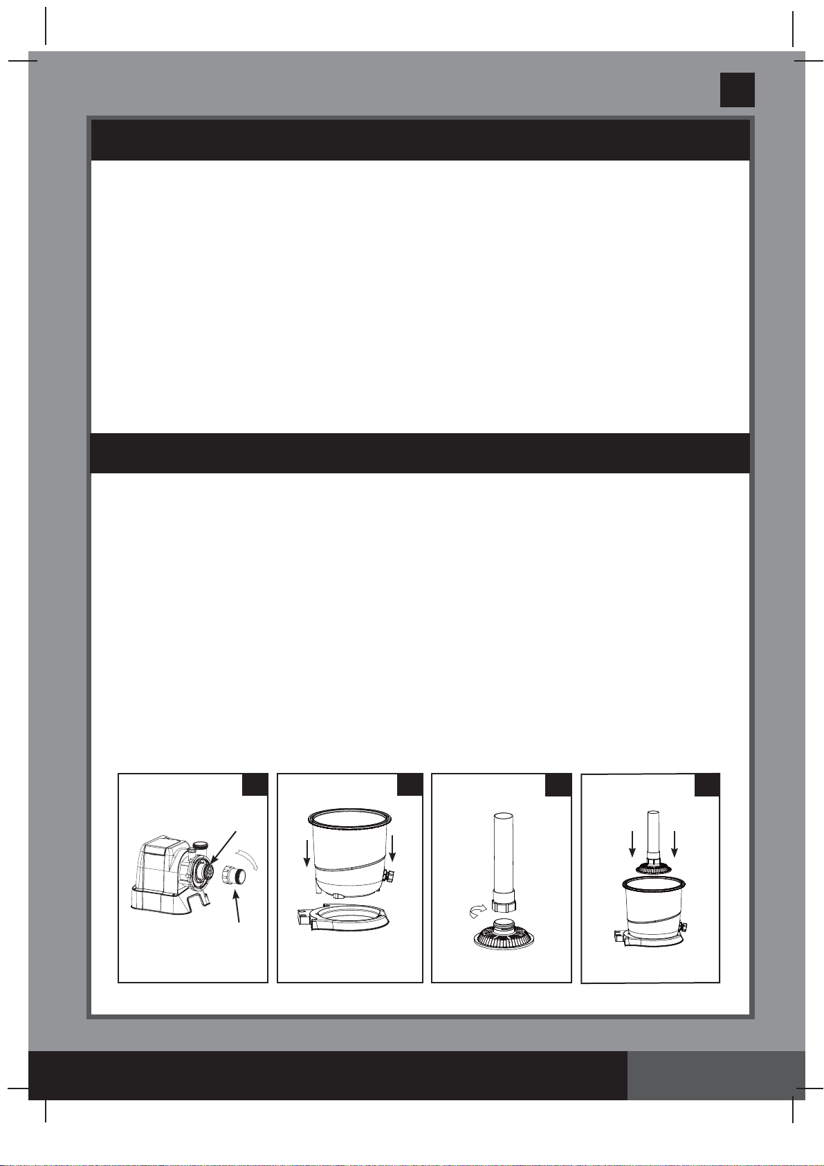
Leaf trap setup:
1.
Make sure the pump o-ring
(6)
is in place. In a clockwise motion screw the leaf trap
(19)
onto the motor inlet
(see drawing 10)
.
Sand tank installation:
1.
Place the tank support base at the selected location.
2.
Place the tank on the tank support base
(see drawing 11.1)
.
11.2
10
19
6
11.1
11.3
Power: 110-120 Volt AC
Amperage: 1.8 A
Maximum working pressure: 1.4 bar (20 psi)
Effective filtering area: 0.05 m
2
(0.54 ft
2
)
Maximum Flow Rate: 4000 liters/hour (1050 gallons/hour)
Recommended filtering media: No. 20 silica sand or glass sand. Particle size
(Not included) range 0.45 to 0.85 mm (0.018 to 0.033 inches).
Uniformity Coefficient less than 1.75.
Recommended filtering media quantity: No. 20 silica sand 12 Kg (26 Lbs) or glass sand
8.5 Kg (18.5 Lbs).
Limited Warranty: see “Limited Warranty”
341
PO
SAVE THESE INSTRUCTIONS
(341PO) MODEL SF90110-1 SAND FILTER PUMP ENGLISH 7.5” X 10.3” PANTONE 295U 06/13/2019
English
Page 10
SETUP INSTRUCTIONS (continued)
3.
In a clockwise motion screw the center pipe
(7)
onto the filter grid
(8)
securely by hand
(see
drawing 11.2)
.
4.
Vertically insert the filter grid and center pipe assembly into the tank. Ensure filter grid
assembly is securely fitted to the bottom of the tank, and the center pipe is vertically
centered inside the tank
(see drawing 11.3)
.
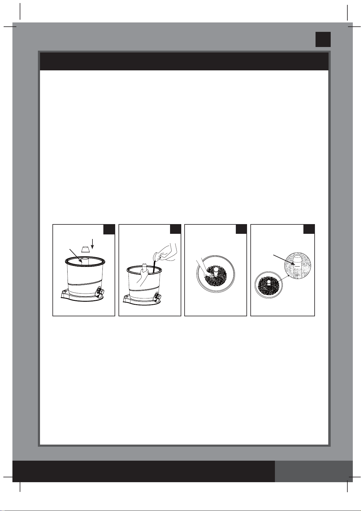
Sand loading:
IMPORTANT: Use No. 20 silica sand or glass sand with particle size range 0.45
to 0.85 mm (0.018 to 0.033 inches) and a Uniformity Coefficient less than 1.75.
NOTE: Before loading the tank with sand, ensure the sand filter grid and center pipe
assembly is securely in place on the tank bottom, and the center pipe (7) is vertically
centered inside the tank.
1.
To prevent sand from falling into the center pipe top opening when pouring the sand, cover
the center pipe top opening with a cup or similar object
(see drawing 12)
.
2.
With one person holding the center pipe to keep it centered, pour the sand into the tank at a
slow rate manually to prevent the filter grid assembly from shifting
(see drawing 13)
.
3.
Fill the tank approximately half way first to evenly distribute the sand inside the tank, then fill
the tank with some water to provide a cushioning effect when the remaining sand is poured
in. This prevents the filter grid
(8)
from excessive shock
(see drawing 14)
.
4.
Sand shall be filled between the “MAX” and “MIN” marked gauge on the center pipe. Evenly
spread and level out the sand by hand
(see drawings 14 & 15)
.
5.
Remove the protective cup from the center pipe top opening.
6.
Wash away all sand around the top edge of the tank.
IMPORTANT: Ensure the center pipe (7) remains centered after sand loading is completed
before proceeding to the next step.
14
MAX
MIN
MAX
MAX
MIN
MIN
15
7
13
12
7
341
PO
SAVE THESE INSTRUCTIONS
(341PO) MODEL SF90110-1 SAND FILTER PUMP ENGLISH 7.5” X 10.3” PANTONE 295U 06/13/2019
English
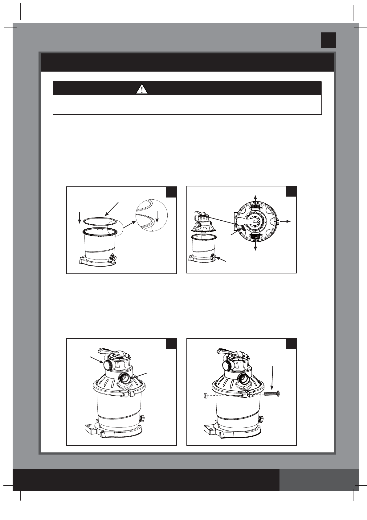
SETUP INSTRUCTIONS (continued)
6-way valve installation:
1.
Make sure the tank o-ring
(5)
is in place
(see drawing 16)
. NOTE: Ensure the tank o-ring is
free of sand or debris.
2.
Lower the 6-way valve cover over the tank slowly, and ensure the bypass pipe protruding
underneath the 6-way valve cover fits securely into the center pipe
(7)
top opening
(see
drawing 17)
. Make sure the tank o-ring is securely fitted between the top edge of the tank
groove and the 6-way valve cover edge.
IMPORTANT:
Ensure the 6-way valve cover ridge
is aligned with the groove on the tank rim.
WARNING
Improper tank valve and clamp assembly could cause the valve and clamp to blow off
and cause serious injury, property damage or death.
IMPORTANT: There are three hose connection ports on the 6-way valve, ensure the
outlet connection (from filter to the pool) on the valve is facing towards the pool (see
drawing 18).
3.
Remove the screw, and install the clamp around the tank and 6-way valve flanges, then
replace the screw and use a phillips screwdriver (not included) to tighten it
(see
drawings 18 & 19)
.
19
17
Page 11
18
WATER
OUTLET
WATER
INLET
16
5
17
WATER
INLET
WATER
OUTLET
TO
DRAIN
DRAIN
VALVE
CAP
DRAIN VALVE
CAP
341
PO
SAVE THESE INSTRUCTIONS
(341PO) MODEL SF90110-1 SAND FILTER PUMP ENGLISH 7.5” X 10.3” PANTONE 295U 06/13/2019
English
Page 12
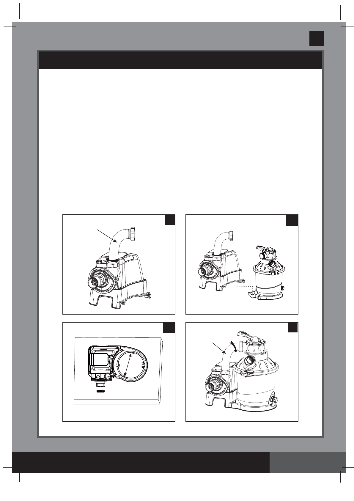
SETUP INSTRUCTIONS (continued)
Motor installation:
1.
Place an L-shape o-ring
(18)
on the pump motor outlet. In a clockwise motion connect the
sand filter interconnecting hose
(13)
to the pump motor outlet
(see drawing 20)
.
2.
Connect the pump motor unit to the tank support base
(see drawing 21.1)
. NOTE: Ensure
the leaf trap water inlet hose connection is facing towards the pool.
IMPORTANT: Some countries, especially in the European community, require the
product to be secured to the ground or to a base in a permanent upright position.
Check your local authorities to determine if there is a regulation in your area
regarding above-the-ground swimming pool filter-pumps. If yes, then the product can
be mounted to a platform using the two holes located in the base. See drawing 21.2.
The product can be mounted on a cement base or onto a wooden platform to prevent
accidental falling over.
• The mounting holes are 6.4 mm in diameter and spaced 196.5 mm apart.
• Use two bolts and lock nuts with a maximum of 6.4 mm in diameter.
3.
Place an L-shape o-ring
(11)
on the 6-way valve inlet connection. In a clockwise motion
connect the sand filter interconnecting hose
(13)
to the 6-way valve inlet connection
(see
drawing 22)
.
21.1
22
13
20
13
21.2
196.5 mm
341
PO
SAVE THESE INSTRUCTIONS
(341PO) MODEL SF90110-1 SAND FILTER PUMP ENGLISH 7.5” X 10.3” PANTONE 295U 06/13/2019
English
Page 13
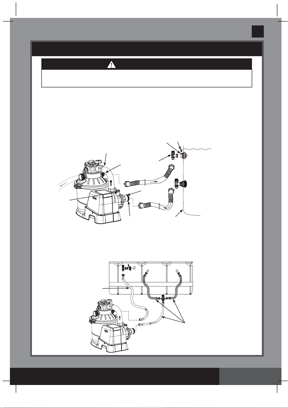
SAND FILTER PUMP HOSE CONNECTION SETUP
The 6-way valve has three hose connection ports.
1.
Connect one hose
(12)
end to the pre-filter inlet and the other end of the hose to the lower
connector with the strainer. Ensure the hoses are securely tightened.
2.
Connect the second hose
(12)
between the 6-way valve water outlet and the upper connector
with the inlet-nozzle. Ensure the hoses are securely tighten.
3.
The third hose connection port (drain/waste outlet) on the 6-way valve shall be directed to
a proper draining receptacle using a hose or pipe (not provided). Remove the drain cap before
attaching the drain/waste hose or pipe.
4.
The sand filter pump is now ready to filter the pool.
WARNING
• Position this product away from the pool, so as to prevent children from climbing on
it and accessing the pool.
(ILLUSTRATION NOT TO SCALE)
For Pools with Dual Suction Outlets Configuration:
In order to comply with the requirement of the Virginia Grahame Baker Act (for USA and
Canada), your pool is designed with dual suction outlets and one inlet fittings. Parts in grey
highlight on this page are supplied with the pool set package and are shown here for assembly
purposes only. If this pump was purchased as part of a pool set, refer to the pool owner’s
manual for more details.
Long hose
Short hose
WATER INLET
WATER INLET
WATER LEVEL
OUTSIDE LINER WALL
PLUNGER
VALVE
L-SHAPE O-RING
L-SHAPE
O-RING
TO
DRAIN
AIR RELEASE
VALVE
AIR JET VALVE
INLET THREADED AIR
CONNECTOR
341
PO
SAVE THESE INSTRUCTIONS
(341PO) MODEL SF90110-1 SAND FILTER PUMP ENGLISH 7.5” X 10.3” PANTONE 295U 06/13/2019
English
Page 14
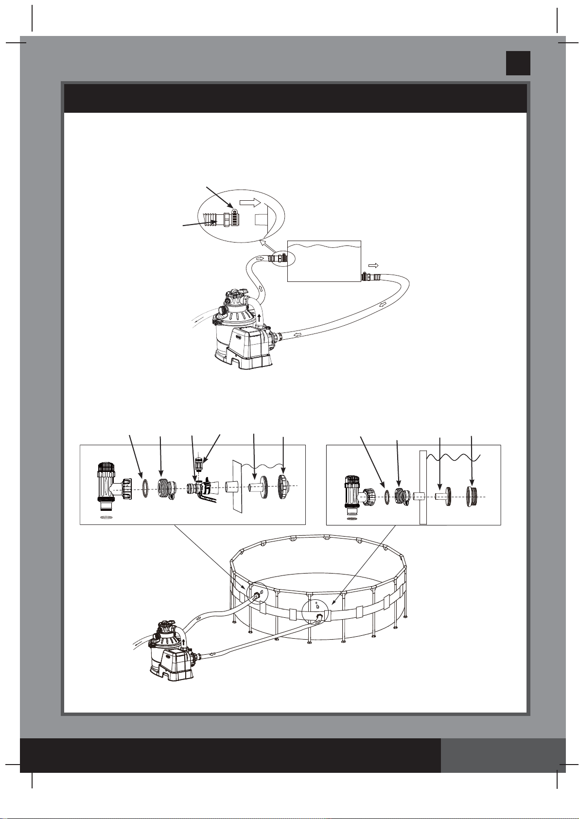
SAND FILTER PUMP HOSE CONNECTION SETUP (continued)
For INTEX pool with 1-1/4” (32mm) connections/hoses:
Make sure the air jet valve
(37)
is securely tighten onto the pool inlet air adaptor
(39)
and facing
up.
For NON-INTEX pool:
Connect the hose
(12)
to the pool inlet/outlet connection with a large hose clamp. Tighten
securely.
POOL
LARGE HOSE
CLAMP
12
40
28
(Adaptor B)
39 37
30
29
31
23
28
(Adaptor B)
23
341
PO
SAVE THESE INSTRUCTIONS
(341PO) MODEL SF90110-1 SAND FILTER PUMP ENGLISH 7.5” X 10.3” PANTONE 295U 06/13/2019
English
Page 15
OPERATING INSTRUCTIONS
• Risk of electric shock. Connect this product only to a grounding type receptacle protected by a
ground-fault circuit interrupter (GFCI) or residual current device (RCD). Contact a qualified electrician if
you cannot verify that the receptacle is protected by a GFCI/RCD. Use a qualified electrician to install
the GFCI/RCD, which has a maximum rate of 30mA. Do not use a portable residual current device
(PRCD).
• To reduce the risk of electric shock, do not use extension cords, timers, plug adaptors or converter
plugs to connect unit to electric supply; provide a properly located outlet.
• Do not attempt to plug in or unplug this product while standing in water or when your hands are wet.
• Never operate this product above the maximum working pressure stated on the filter tank.
• Always switch off pump before changing the 6-way valve position.
• Operating this product without water flowing through the system can cause a build up of hazardous
pressure which can result in an explosive situation, serious injury, property damage or death.
• Never test this pump with compressed air. Never operate the system with water temperature
above 35° C (95° F).
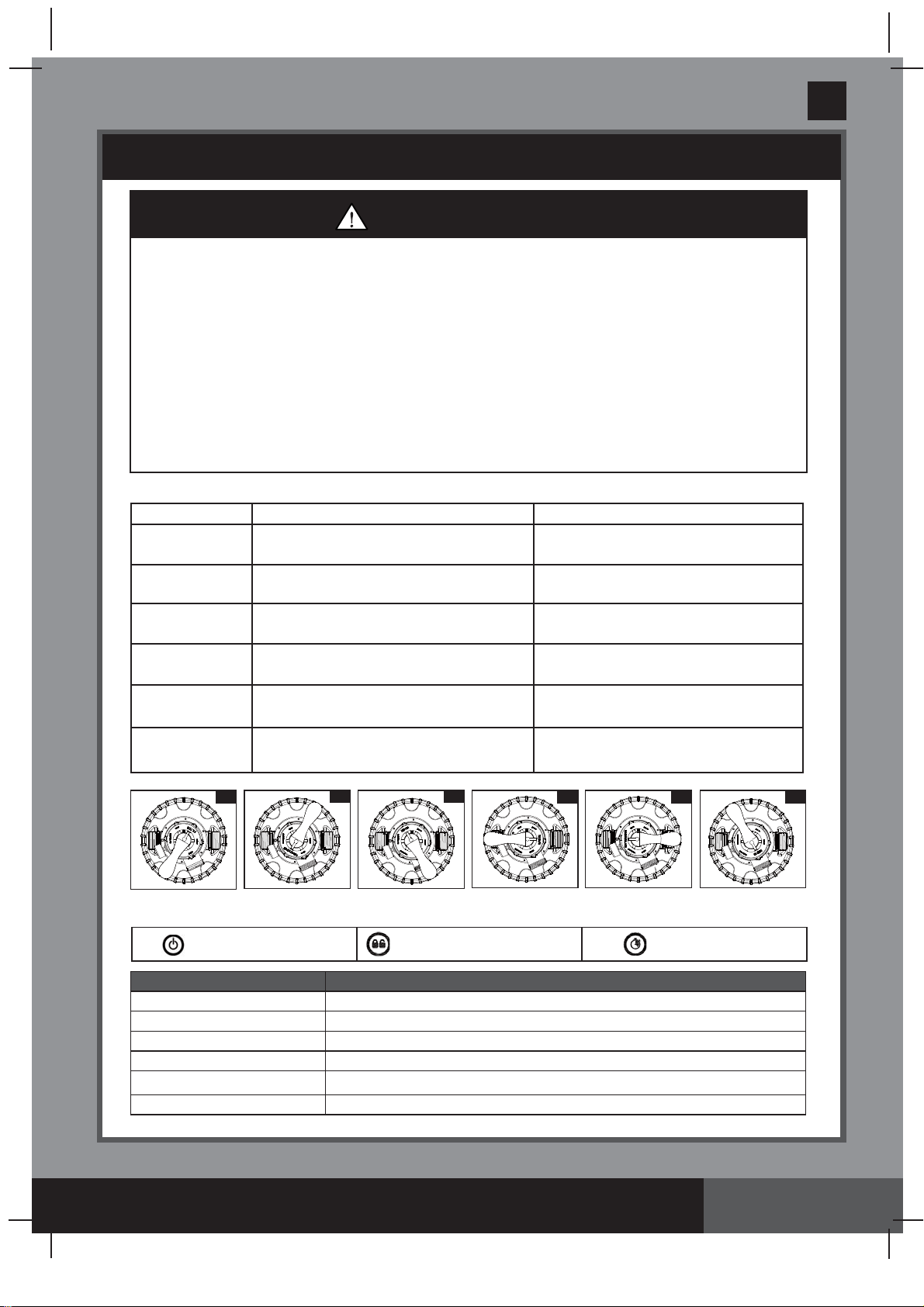
Valve Position Function Water Flow Direction
FILTER
(see drawing 23)
Normal filtration and regular vacuuming
of pool
From pump through filter media to
pool
BACKWASH
(see drawing 24)
Reverses water flow to clean filter
media
From pump through filter media to
valve waste/drain outlet
RINSE
(see drawing 25)
For initial startup cleaning of the sand, and
leveling the sand bed after backwashing
From pump through filter media to
valve waste/drain outlet
WASTE
(see drawing 26)
For vacuuming directly to waste,
lowering pool level or to drain the pool
From pump to valve waste/drain
outlet bypassing the filter media
RECIRCULATE
(see drawing 27)
For circulating water back to pool
without going through the filter media
From pump through valve to
pool bypassing the filter media
CLOSED
(see drawing 28)
Shuts off all flow to filter and pool
“Do not use this setting with pump running”
6-way valve positions and function:
WARNING
23
26
27
28
24 25
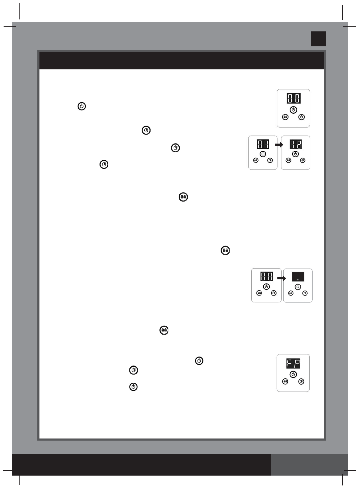
Control panel description:
ON / OFF button LOCK / UNLOCK button TIMER button
LED Reading Definition
00 Stand-by mode (start-up / operating cycle finished)
01 Minimum operating hour (1 hour remaining)
02-11 Operating hours (2 – 11 hours remaining)
12 Maximum operating hours (12 hours remaining)
FP
Timer OFF (pump operating continuously)
Power saving mode
.
341
PO
SAVE THESE INSTRUCTIONS
(341PO) MODEL SF90110-1 SAND FILTER PUMP ENGLISH 7.5” X 10.3” PANTONE 295U 06/13/2019
English
Page 16
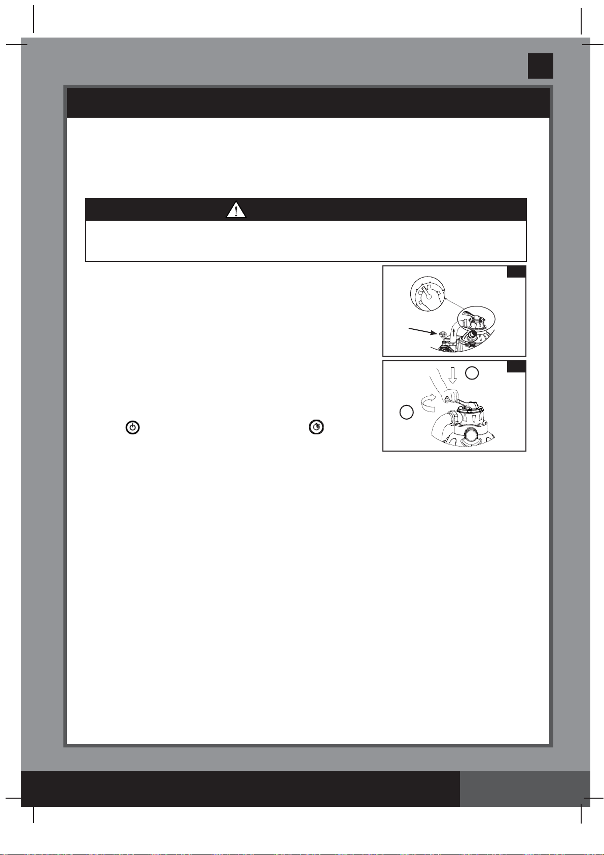
Initial startup and operation:
Before operating, be sure that:
• All the hoses have been connected and tightened securely, and correct amount of filter sand
have been loaded.
• The entire system is connected to a grounding type receptacle protected by a ground-fault
circuit interrupter (GFCI) or residual current device (RCD).
OPERATING INSTRUCTIONS (continued)
CAUTION
The filter control valve has a closed position. The pump should never be on when the
valve is in the closed position. If the pump is operated with the valve closed, explosive
situation could exist.
N
29
36
30
1
2
1.
Turn both plunger valve handles fully counter-clockwise until they
stop. This opens the valves to allow water to flow into the sand
filter pump.
2. Release air from the system -
Ensure the drain/waste outlet on
the 6-way valve is not covered and directed to a proper draining
receptacle, and the pump is off. Turn the 6-way valve to the “N”
position and unscrew the air release valve
(36)
from the motor
housing
(see drawing 29)
. When water starts flowing out of the
air release valve hole, close the air release valve back.
3.
BACKWASH
- Ensure the pump is off, depress the 6-way valve
and turn it to the “
BACKWASH
” position
(see drawings 24 & 30)
.
IMPORTANT: To prevent damage to the 6-way valve, always
depress the valve handle before turning. Always switch off
pump before changing the 6-way valve position.
4.
Press
to switch on the system, and then press to set
the operating TIMER hours (see “Operating the system under
TIMER mode or manually” section for details). Water is circulating
backward through the sand media and to waste/drain outlet. Backwash until a clear flow of water is
observed in the waste/drain outlet or through the transparent outlet adaptor.
NOTE:
If the LED display flashes “00”, the device is in stand-by mode and the pump will not operate.
The initial backwash of the filter is recommended to remove any impurities or fine sand particles in the
sand media.
5.
Switch off the pump, change the 6-way valve to “RINSE” position
(see drawing 25)
.
6.
Switch on the pump and run the pump for about one minute to level out the sand bed after backwashing
the sand media.
7.
Switch off the pump, change the 6-way valve to “FILTER” position
(see drawing 23)
.
8.
Switch on the pump. The system is now operating in the normal filtering mode. Run the pump until the
desired pool water clearance is obtained and no more than 12 hours per day. For the initial startup, it is
recommended setting the system to a longer TIMER operating hours or “FP” for the pump to operate
continuously without the TIMER.
9.
Record the initial pressure gauge reading when the filter media is clean.
NOTE:
During initial setup of the system, it may be necessary to backwash frequently due to unusual
heavy dirt present in the water and sand. After that, as the filter removes dirt and impurities from the pool
water, the accumulated dirt in the sand media will cause the pressure to rise and the flow to diminish. If
there is no vacuuming device attached to the system and the pressure gauge reading is in the yellow
zone it is time to backwash the sand media, see “BACKWASH” under “initial startup and operation”
section.
Vacuuming device (i.e. Intex auto pool cleaner) attached to the system may also cause the flow to
diminish and the pressure to rise. Remove any vacuuming device from the system and check if the
pressure gauge reading has dropped from the yellow zone to the green zone.
10.
Monitor the pressure gauge reading, and check that the inlet and outlet openings are not obstructed on a
weekly basis. If the pressure gauge indicates yellow it is time to backwash the filter media.
341
PO
SAVE THESE INSTRUCTIONS
(341PO) MODEL SF90110-1 SAND FILTER PUMP ENGLISH 7.5” X 10.3” PANTONE 295U 06/13/2019
English
Page 17
OPERATING INSTRUCTIONS (continued)
Operating the system under “TIMER” mode or manually:
To operate the sand filter pump in “FILTER” mode under “TIMER” control:
1. Activate the unit:
Press button. Flashing code “00” appears on the LED display, indicating
that the unit is ready to be programmed.
2. Set operating hours:
With code “00” flashing, press
button to set the desired operating
hours. See the “Operating Time Table” for the required operating
hours related to each pool size. Pressing
will increase the time
from 01 to 12 hours maximum. If you have selected too many hours
keep pressing to repeat the cycle. The built-in timer will now
activate the Sand filter pump, at the same time each day, for the
number of hours you have set.
3.
Lock keypad controls:
With the desired hour value showing, press
button until you hear a “beep”. Locking the
control buttons into this setting prevents unauthorized changing of the operating cycle.
NOTE:
If you forget to lock the keypad controls, the system will automatically lock it and start
working 10 seconds later.
The sand filter pump is now filtering the water and will stop after the operating hours are
completed.
4.
Readjust operating time if necessary:
The operating hours can be re-adjusted if necessary. Press
button until you hear a “beep”
to unlock the keypad and the current programmed time will flash. Repeat steps 2 to 3.
5. Stand-by/power saving mode:
•
When the cycle ends, the LED display shows “00”. The system is now
in Stand-By mode. After 5 minutes the system goes into Power
Saving mode and the LED display shows “.”. The system will
automatically turn itself back on in 24 hours.
• While the system is in Power Saving mode, press any button and the
system will briefly display the programmed time and then “00”.
To view the TIMER preset hours:
While the pump is operating, press “ ” button, the display will briefly flash the preset hours
for 10 seconds and then display back the remaining operating hours.
To operate the sand filter pump manually (without the “TIMER” mode):
1.
To run the pump alone without the “Timer”, press
button to turn
on the pump, then press button until the LED displays “FP”, this
indicates that the TIMER is off and the pump is now operating continuously.
2.
To stop the pump, press
button again.
(1 to 12 hours max per cycle)
341
PO
SAVE THESE INSTRUCTIONS
(341PO) MODEL SF90110-1 SAND FILTER PUMP ENGLISH 7.5” X 10.3” PANTONE 295U 06/13/2019
English
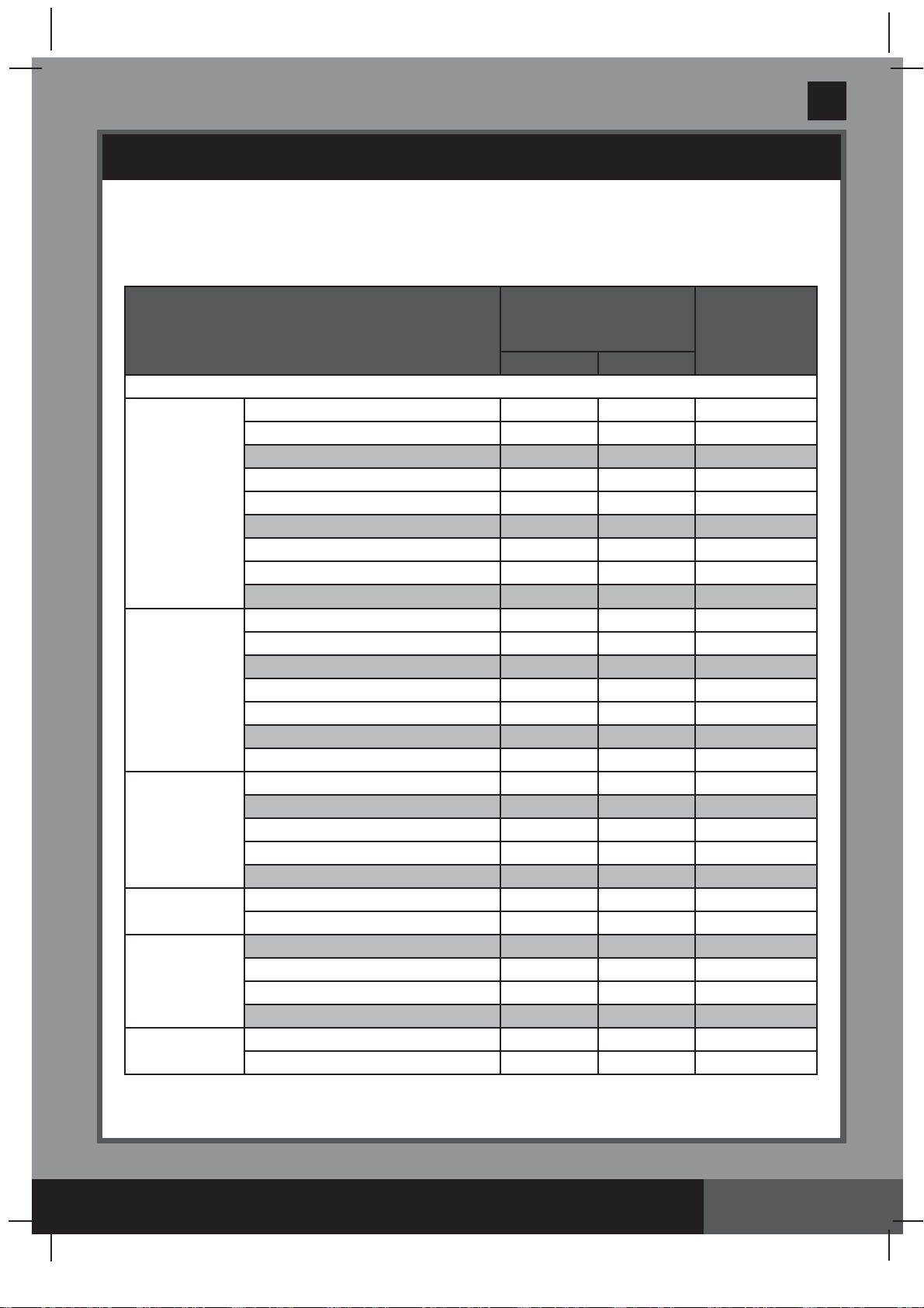
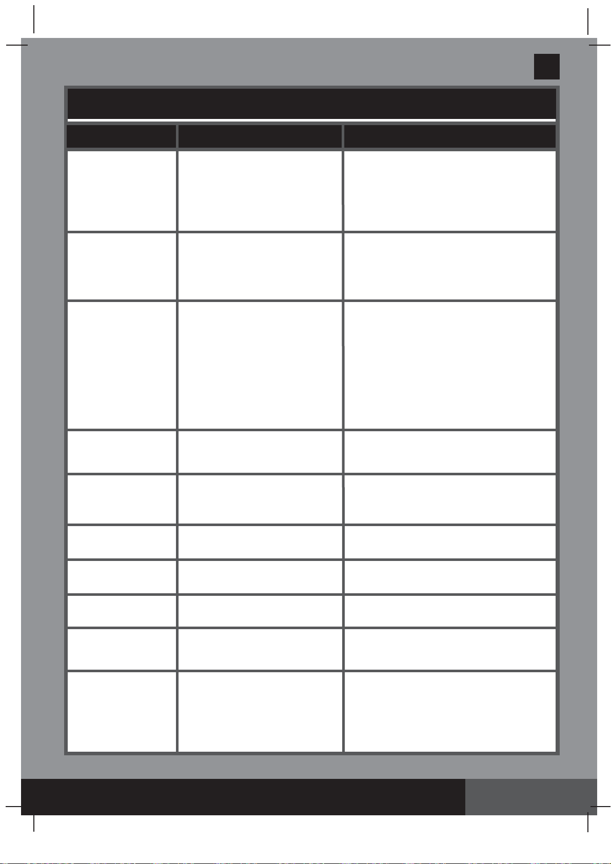
Page 18
INTEX POOLS OPERATING TIME TABLE (WITHOUT INTEX SALTWATER SYSTEM)
This table shows the required operating time for average use of the sand filter pump with above
ground pools.
If the system is attached to an “Intex Saltwater System” unit, the filter pump running time
should be longer than the required operating time of the Intex Saltwater System unit.
Pool Size
Water Capacity (Calculated at
90% for Frame Pool and 80%
for Easy Set & Oval Pool)
Sand filter pump
operating time
(For one cycle) /
(Hours)
(Gals) (Liters)
INTEX ABOVE GROUND POOLS (AGP’s)
EASY SET
®
POOL
15' x 33" (457cm x 84cm)
2587 9792 3
15' x 36" (457cm x 91cm)
2822 10681 3
15' x 42" (457cm x 107cm)
3284 12430 4
15' x 48" (457cm x 122cm)
3736 14141 4
16' x 42"(488cm x 107cm)
3754 14209 4
16' x 48" (488cm x 122cm)
4273 16173 5
18' x 42" (549cm x 107cm)
4786 18115 5
18' x 48" (549cm x 122cm)
5455 20647 6
18' x 52" (549cm x 132cm)
5894 22309 6
ROUND
METAL
FRAME POOL
12' x 36" (366cm x 91cm)
2086 7896 2
15' x 36" (457cm x 91cm)
3282 12422 4
15' x 42" (457cm x 107cm)
3861 14614 4
15' x 48" (457cm x 122cm)
4440 16805 5
16' x 48" (488cm x 122cm)
5061 19156 5
18' x 48" (549cm x 122cm)
6423 24311 7
18' x 52" (549cm x 132cm)
6981 26423 7
ULTRA FRAME
POOL
12' x 36" (366cm x 91cm)
2086 7896 2
14' x 48" (427cm x 122cm)
3861 14614 4
16' x 48" (488cm x 122cm)
5061 19156 5
18' x 48" (549cm x 122cm)
6423 24311 7
18' x 52" (549cm x 132cm)
6981 26423 7
GRAPHITE GRAY
PANEL POOL SET™
16'8" x 49" (508cm x 124cm)
5061 19156 5
18'8" x 53" (569cm x 135cm)
6981 26423 7
OVAL FRAME
POOL
18' x 10' x 42" (549cm x 305cm x 107cm)
2885 10920 3
20' x 12' x 48" (610cm x 366cm x 122cm)
4393 16628 5
24' x 12' x 48" (732cm x 366cm x 122cm)
5407 20465 6
28' x 12' x 48" (853cm x 366cm x 122cm)
6420 24300 7
RECT. ULTRA
FRAME POOL
15' x 9' x 48" (457cm x 274cm x 122cm)
3484 13187 4
18' x 9' x 52" (549cm x 274cm x 132cm)
4545 17203 5
NOTE: The timer setting has an additional 10 minutes over the actual setting.
341
PO
SAVE THESE INSTRUCTIONS
(341PO) MODEL SF90110-1 SAND FILTER PUMP ENGLISH 7.5” X 10.3” PANTONE 295U 06/13/2019
English
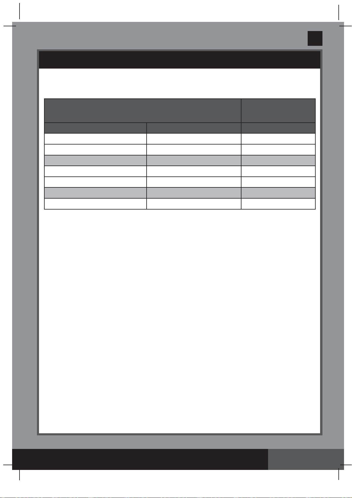
Page 19
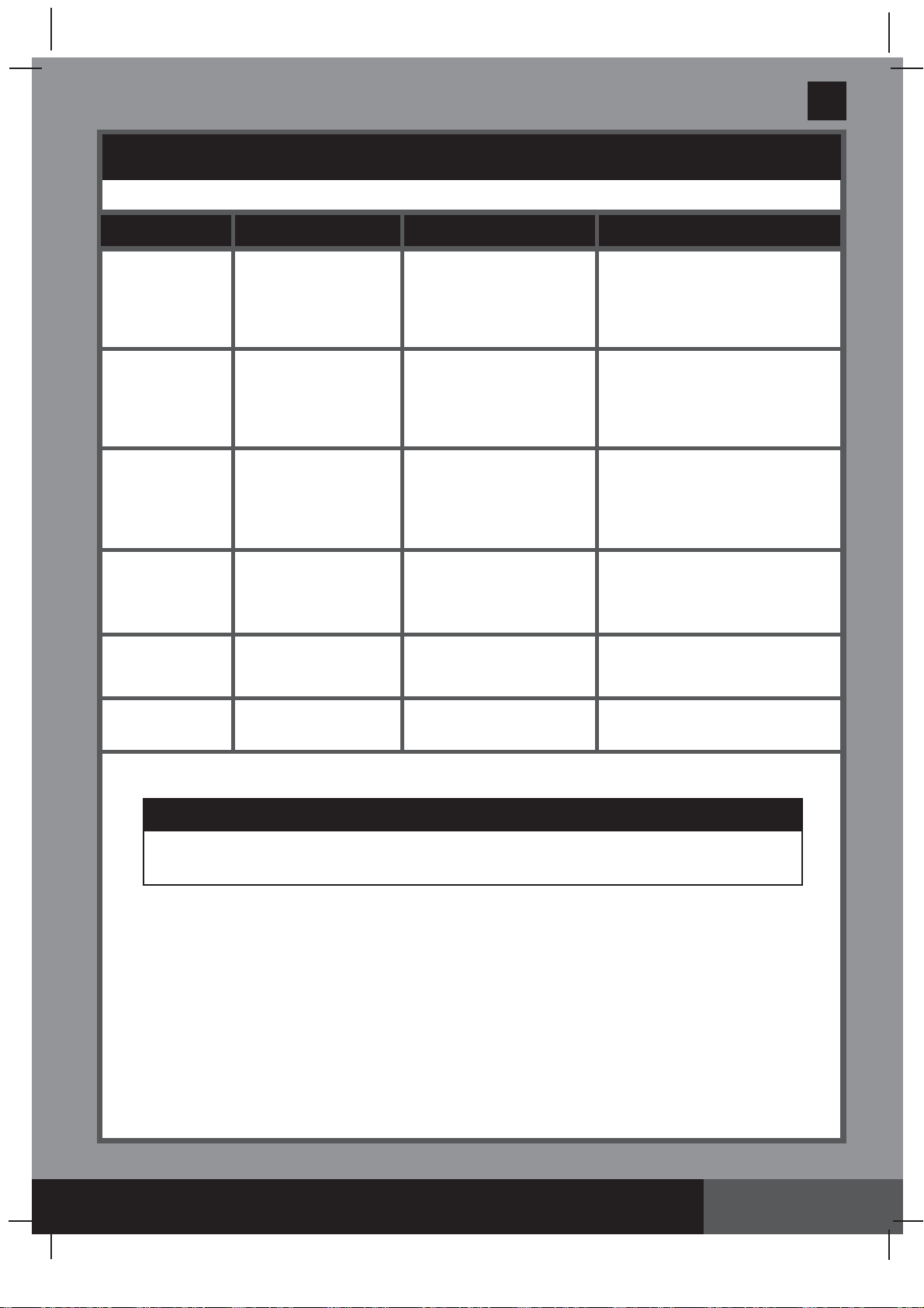
NON-INTEX POOLS OPERATING TIME TABLE
This table shows the required operating time for average use of the sand filter pump with
above ground pools.
Water Capacity
Sand filter pump operating
time (For one cycle)
(Gals) (Liters) (Hours)
2000 7570 2
3000 11355 3
4000 15140 4
5000 18925 5
6000 22710 6
7000 26495 7
8000 30280 8
341
PO
SAVE THESE INSTRUCTIONS
(341PO) MODEL SF90110-1 SAND FILTER PUMP ENGLISH 7.5” X 10.3” PANTONE 295U 06/13/2019
English
Page 20
1.
Before emptying your pool for long term storage, or relocation, be sure the water is directed
towards an acceptable drain water receptacle away from the house. Check local regulations
for specific directions regarding disposal of swimming pool water.
2.
Switch off the unit, and disconnect power cord from electrical outlet.
3.
When the pool is empty, disconnect all hoses from pump and plunger valves and remove the
strainers/plunger valves from the pool wall.
4.
In a counter clockwise motion unscrew the drain valve cap
(9)
from the drain valve
to
thoroughly drain the tank. The drain valve is located at the bottom of the filter tank.
5.
Disassemble the pump motor from the tank base.
6.
Leave sand filter pump pieces and hoses outside to thoroughly air dry.
7.
Coat the following o-rings and washers with petroleum jelly for long term storage:
• L-shape o-rings
(11 & 18)
.
• Pump hose o-rings
(22)
.
• Strainer valve assembly step washers
(23)
.
• Flat strainer rubber washers
(25)
.
8.
Depress the 6-way valve handle and rotate so as to set the pointer on the valve top “N”
position. This allows the water to drain from the valve. Leave the 6-way valve in this inactive
position.
9.
It is best to place all dry pieces and pump motor in the original packaging for storage. To avoid
condensation or corrosion problem, do not cover or wrap pump motor with plastic bags.
10.
Store the pump motor and accessories in a dry place. The storage's temperature should be
controlled, between 0 degrees Celsius (32 degrees Fahrenheit) and 40 degrees Celsius
(104 degrees Fahrenheit).
POOL CARE & CHEMICALS
• All pools require care to keep the water clear and hygienically clean. With proper chemical
control, your filter will help attain this objective. Consult your pool supply dealer for
instructions regarding the proper use of chlorine, algaecide and other chemical agents
required for sparkling clear water.
• Keep pool chemicals away from children.
• Do not replenish chemicals in pool while pool is occupied. Skin or eye irritations could occur.
• Daily pH checking and chemical treatment of the water is very important and cannot be
overemphasized. Chlorine, algaecide and maintenance of proper pH levels are required when
filling the pool as well as during the season. Consult your local swimming pool supply store
for instructions.
• The season's first filling of the pool may have brackish water requiring extra water additives
and extra filtering time. Do not allow swimming in pool until the pH level is balanced. Consult
your local swimming pool supply store for instructions.
• Chlorinated water may damage lawns, gardens or shrubbery as children play in the pool and
splash water outside the pool. Lawn areas underneath the pool liner will be destroyed. Note
that some types of grass may grow through the liner.
• Filter run time depends on pool size, weather and usage level. Experiment with various run
times so as to produce clean clear water.
LONG TERM STORAGE & WINTERIZATION
CAUTION
Concentrated chlorine solutions may damage the pool liner. Always follow the chemical
manufacturer’s directions, and the health and hazard warnings.
CAUTION
Allowing the water to freeze will damage the sand filter and void the warranty.
341
PO
SAVE THESE INSTRUCTIONS
(341PO) MODEL SF90110-1 SAND FILTER PUMP ENGLISH 7.5” X 10.3” PANTONE 295U 06/13/2019
English
Page 21
TROUBLESHOOTING GUIDE
TROUBLE CAUSE SOLUTION
• Line cord must be plugged into a 3 wire outlet
that is protected by a Class A Ground Fault
Circuit Interrupter, or RCD.
• Reset circuit breaker. If circuit breaker trips
repeatedly, your electrical system may have a
defect. Turn off circuit breaker and call an
electrician to correct the problem.
• Let the motor cool down and restart again.
• Adjust the chlorine and pH level. Consult your
local swimming pool supply stores.
• Load with filter sand, see “sand loading
instructions”.
• Set valve to “FILTER” position.
• Operate the filter for longer periods.
• Clean the strainer screen at the inlet.
•
Release the air, see operating instructions section.
• Clear any obstructions in the intake hose by
discharging it inside pool wall.
• Tighten hose nuts, check hoses for damage,
check pool water level.
• Backwash filter.
• Install the nozzle at the upper position of the
pool inlet, and the strainer at the lower
position of the pool outlet.
• Remove about 1” of sand if necessary.
• Remove any pool vacuuming device attached
to the system line.
• Make sure the inlet threaded air connector is
connected to the pool inlet upper hole.
• Fill pool to correct water level.
• Clean strainer screens at pool inlet.
• Tighten hose nuts, check hose for damage.
• Contact Intex service center.
• Remove 6-way valve cover and ensure the
o-ring is in place.
• Clean sand tank o-ring with garden hose water.
• Tighten securely.
• Contact Intex service center.
• Tighten/reinstall hose nut.
• Ensure o-ring/L-shape o-ring is in place and
not damaged.
• Turn off the pump and restart 5 minutes later.
• Re-set the timer.
• Contact Intex service center.
• Clear any obstructions in the intake by
unscrewing it from the 6-way valve.
• Contact Intex service center.
• Use only No. 20 silica sand with particle size
range 0.45 to 0.85 mm (0.018 to 0.033 inches)
and a Uniformity Coefficient less than 1.75.
• Change sand.
• Tighten or reinstall plunger valve.
• Tighten air jet valve and make sure it’s
facing up.
• Turn pump ON and run for few seconds, then
turn OFF, repeat 3 times.
• Remove air jet valve, flush dirt out with water
and replace valve back.
• Replace a new air jet valve.
FILTER MOTOR
FAILS TO START
FILTER DOESN’T
CLEAN POOL
FILTER DOESN’T
PUMP WATER OR
FLOW IS VERY
SLOW
PUMP DOESN’T
WORK
6-WAY VALVE/
COVER LEAKING
HOSE LEAKING
TIMER IS
INACCURATE OR
TIMER CAN'T BE SET
PRESSURE GAUGE
DOESN’T WORK
SAND IS FLOWING
BACK INTO THE
POOL
INLET TREADED
AIR CONNECTOR
/ AIR JET VALVE
LEAKING
• The motor is not plugged in.
• The GFCI/RCD circuit breaker is
tripped.
• Motor too hot and overload
protection is shut off.
• Improper chlorine or pH levels.
• No filtering media in tank.
• Wrong 6-way valve setting
position.
• Excessively dirty pool.
• The strainer screen is restricting
the water flow.
• Trapped air in the system.
• Clogged inlet or discharge.
• An air leak on the intake line.
• Excessively dirty pool.
• Sand media clogged with dirt.
• Nozzle and strainer connections
are reversed.
• Crusting or caking on the filtering
sand surface.
• Pool vacuuming device attached
to the system.
• Inlet threaded air connector
connected to the wrong hole on
the liner.
• Low water level.
• Strainer screen clogged up.
• An air leak on the intake hose.
• Faulty motor or the impeller is jammed.
• Sand tank o-ring missing.
• Sand tank o-ring dirty.
• Flange clamp not tight.
• 6-way valve damage.
• Hose nut not securely tight.
• Hose connection fitting
o-ring/L-shape o-ring missing.
• Possible inner timer defective.
• Clogged inlet of the pressure
gauge.
• Pressure gauge damage.
• Sand is too small.
• Sand bed is calcified.
• Plunger valve not well-fitted.
• Air jet valve is not tight and
facing up.
• Air jet valve internal seal blocked.
• Air jet valve internal seal dirty.
• Air jet valve broken.
341
PO
SAVE THESE INSTRUCTIONS
(341PO) MODEL SF90110-1 SAND FILTER PUMP ENGLISH 7.5” X 10.3” PANTONE 295U 06/13/2019
English
Page 22
COMMON POOL PROBLEMS
PROBLEM DESCRIPTION CAUSE SOLUTION
ALGAE
COLORED
WATER
FLOATING
MATTER IN
WATER
CHRONIC LOW
WATER LEVEL
SEDIMENT ON
POOL BOTTOM
SURFACE
DEBRIS
• Chlorine and pH levels
need adjustment.
• Copper, iron or maganese
in water being oxidized by
the added chlorine.
• "Hard water" caused by a
too high pH level.
• Chlorine content is low.
• Foreign matter in water.
• Rip or hole in pool liner or
hoses.
• The drain valves are loose.
• Heavy use, getting in and
out of pool.
• Pool too close to trees.
• Super chlorinate with shock
treatment. Correct pH to your
pool store's recommended level.
• Vacuum pool bottom.
• Maintain proper chlorine level.
• Adjust pH level to the
recommended level.
• Run filter until water is clear.
• Correct the pH level. Check with
your pool dealer for advice.
• Adjust the chlorine level.
• Repair with a patch kit.
• Finger tighten all caps.
• Use Intex pool vacuum to clean
of pool.
• Use Intex pool skimmer.
• Greenish water.
• Green or black spots
on pool liner.
• Pool liner is slippery
and/or has a bad odor.
• Water turns blue,
brown, or black
when first treated
with chlorine.
• Water is cloudy or
milky.
• Level is lower than
on previous day.
• Dirt or sand on pool
floor.
• Leaves, insects etc.
IMPORTANT
If you continue to experience difficulty, please contact our Consumer Service Department for
assistance. See separate “Authorized Service Centers” sheet.

341
PO
SAVE THESE INSTRUCTIONS
(341PO) MODEL SF90110-1 SAND FILTER PUMP ENGLISH 7.5” X 10.3” PANTONE 295U 06/13/2019
English
Water recreation is both fun and therapeutic. However, it involves inherent risks
of injury and death. To reduce your risk of injury, read and follow all product,
package and package insert warnings and instructions. Remember, however, that
product warnings, instructions and safety guidelines cover some common risks
of water recreation, but do not cover all risks and dangers.
For additional safeguards, also familiarize yourself with the following general
guidelines as well as guidelines provided by nationally recognized Safety
Organizations:
• Demand constant supervision. A competent adult should be appointed as a “lifeguard”
or water watcher, especially when children are in and around the pool.
• Learn to swim.
• Take the time to learn CPR and first aid.
• Instruct anyone who is supervising pool users about potential pool hazards and about
the use of protective devices such as locked doors, barriers, etc.
• Instruct all pool users, including children what to do in case of an emergency.
• Always use common sense and good judgement when enjoying any water activity.
• Supervise, supervise, supervise.
For additional information on safety, please visit
• The Association of Pool and Spa Professionals: The Sensible Way to Enjoy
Your Aboveground/Onground Swimming Pool www.nspi.org
• American Academy of Pediatrics: Pool Safety for Children www.aap.org
• Red Cross www.redcross.org
• Safe Kids www.safekids.org
• Home Safety Council: Safety Guide www.homesafetycouncil.org
• Toy Industry Association: Toy Safety www.toy-tia.org
GENERAL AQUATIC SAFETY
Page 23

341
PO
SAVE THESE INSTRUCTIONS
(341PO) MODEL SF90110-1 SAND FILTER PUMP ENGLISH 7.5” X 10.3” PANTONE 295U 06/13/2019
English
Page 24
LIMITED WARRANTY
Your Sand Filter Pump has been manufactured using the highest quality materials and
workmanship. All Intex products have been inspected and found free of defects prior to
leaving the factory. This Limited Warranty applies only to the Sand Filter Pump and
accessories listed below.
The provisions of this Limited Warranty apply only to the original purchaser and is not
transferable. This Limited Warranty is valid for the period noted below from the date of the
initial retail purchase. Keep your original sales receipt with this manual, as proof of purchase
will be required and must accompany warranty claims or the Limited Warranty is invalid.
Sand Filter Pump Warranty – 2 Years
Hoses, Plunger Valves & Fittings Warranty – 180 days
If a manufacturing defect is found within the periods noted above, please contact the
appropriate Intex Service Center listed in the separate “Authorized Service Centers” sheet.
The Service Center will determine the validity of the claim. If the Service Center directs you
to return the product, please carefully package the product and send with shipping and
insurance prepaid to the Service Center. Upon receipt of the returned product, the Intex
Service Center will inspect the item and determine the validity of the claim. If the provisions
of this warranty cover the item, the item will be repaired or replaced at no charge.
Any and all disputes regarding the provisions of this Limited Warranty shall be brought before
an informal dispute settlement board and unless and until the provisions of these paragraphs
are carried forth, no civil action may be instituted. The methods and procedures of this
settlement board shall be subject to the rules and regulations set forth by the Federal Trade
Commission (F.T.C.). IMPLIED WARRANTIES ARE LIMITED TO THE TERMS OF THIS
WARRANTY AND IN NO EVENT SHALL INTEX, THEIR AUTHORIZED AGENTS OR
EMPLOYEES BE LIABLE TO THE BUYER OR ANY OTHER PARTY FOR DIRECT OR
CONSEQUENTIAL DAMAGES OR LIABILITIES. Some states, or jurisdictions do not allow
the exclusion or limitation of incidental or consequential damages, so the above limitation or
exclusion may not apply to you.
This Limited Warranty does not apply if the products are subject to negligence, abnormal use
or operation, accident, improper operation, improper voltage or current contrary to operating
instructions, or to damage by circumstances beyond Intex’s control, including but not limited
to, ordinary wear and tear and damage caused by exposure to fire, flood, freezing, rain, or
other external environmental forces. This Limited Warranty applies only to those parts and
components sold by Intex. The Limited Warranty does not cover unauthorized alterations,
repairs or disassembly by anyone other than Intex Service Center personnel.
DO NOT GO BACK TO THE PLACE OF PURCHASE FOR RETURN
OR REPLACEMENT. IF YOU ARE MISSING PARTS OR NEED
ASSISTANCE, PLEASE CALL US TOLL-FREE (FOR U.S. AND
CANADIAN RESIDENTS): 1-800-234-6839 OR VISIT OUR WEBSITE:
WWW.INTEXCORP.COM.
Proof of Purchase must accompany all returns or the warranty claim will be invalid.