INSTALLATION AND USER’S GUIDE
SKU: 90165
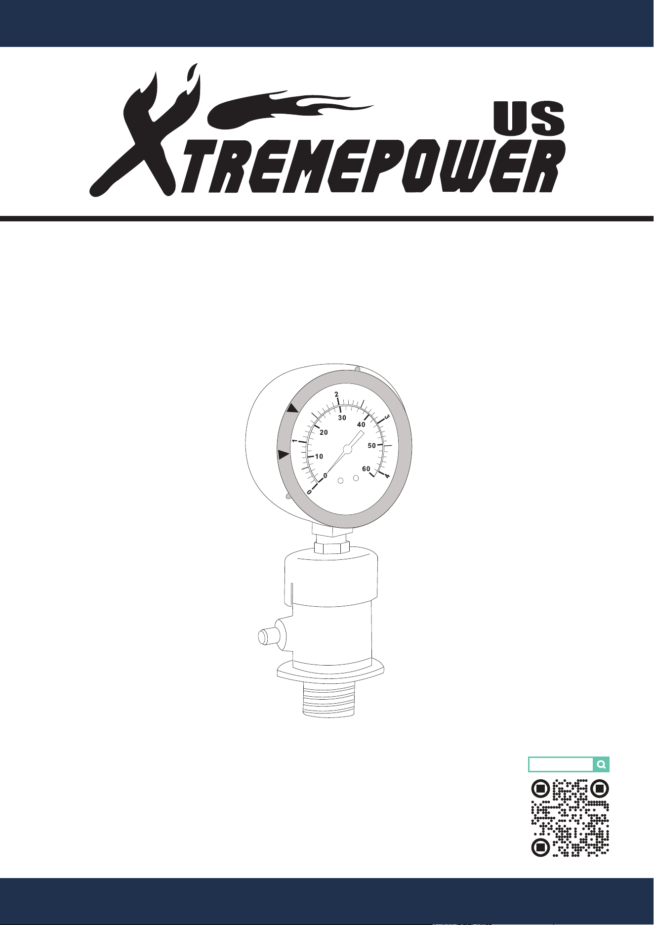
POOL FILTER MANUAL AIR RELIEF VALVE
90165
psi
bar
S
T
A
R
T
C
L
E
A
N
F
I
L
T
E
R
WITH AIR PRESSURE GAUGE


TABLE OF CONTENTS
1
6DISCLAIMER
INTRODUCTION
5INSTALLATION INSTRUCTIONS
5INSTALLATION
4
4PACKAGING CONTENTS
4PRODUCT INFORMATION
2
Legends and Symbols
2IMPORTANT SAFETY INSTRUCTIONS
1TABLE OF CONTENTS
6Customer Service
6Disclaimer
5Step 2: New Manual Air Relief Assembly
5Step 1: Initial Setup
5Step 4: Air Pressure Gauge Installation
5Step 3: New Manual Air Relief Installation
IMPORTANT SAFETY INSTRUCTIONS
2
For safety reasons, children should not be allowed to use this product.
Packing materials and plastic bags are not toys. Keep them away from children to prevent the risk
of suffocation.
Failure to comply with all instructions and warnings may lead to severe bodily
injury or even death. For optimal safety and functionality, it is advisable to have the product installed
and serviced by a certified service professional. Prior to using this product, installers, operators, and
owners must carefully review these warnings and all instructions provided in the owner's manual. It
is essential to leave these warnings and the owner's manual with the owner for their reference and
safety.
ATTENTION INSTALLER: This manual contains vital information regarding the installation,
operation, and safe use of this product. It is essential to provide this manual to the end user of the
product. Failure to read and follow all instructions could lead to severe injuries.
USE OF NON-XTREMEPOWERUS REPLACEMENT PARTS VOIDS WARRANTY
DANGER: Ignoring these hazards can result in death, severe personal injury, or
significant property damage.
WARNING: Indicates potential hazards that can result in severe personal injury,
death, or significant property damage. Ignoring these warnings presents a real
danger.
CAUTION: Indicates potential hazards that can result in minor or moderate
personal injury, property damage, or actions that are unpredictable and unsafe.
Ignoring these cautions presents a potential hazard.
NOTICE: This label indicates important special instructions that are not directly
related to hazards.
This guide provides instructions for installing and using the DE FILTER REPLACEMENT GRID
SET. If you have any questions about the equipment, please contact XtremepowerUS.
This guide contains important information about safely installing and operating this product. After
installation, make sure to share this information with the owner/operator or leave it with them for
their reference.
Legends and Symbols
When you come across the safety-alert symbol on your equipment or in this manual, pay attention
to the following signal words and remain vigilant about the potential for personal injury.
IMPORTANT SAFETY INSTRUCTIONS
DANGER
WARNING
WARNING
CAUTION
NOTE
DANGER
IMPORTANT SAFETY INSTRUCTIONS
3
GENERAL SAFETY INFORMATION
DANGER
• Pressure Precautions: Never open the air relief valve while the system is pressurized.
Ensure all pressure is safely released from the system to avoid the risk of injury or damage
due to sudden discharge of air or water.
• Power Safety: Ensure the pool pump and any associated systems are powered off before
attempting installation or maintenance on the air relief valve to prevent electrical hazards.
• Proper Installation: Incorrect installation may lead to water leakage, system malfunction, or
failure, potentially causing damage to pool equipment or the environment.
• Keep Clear During Operation: Maintain distance from the air relief valve during operation,
as sudden discharges of air or water can occur.
WARNING
CAUTION
NOTE
• Hand Tighten Only: When installing the valve and pressure gauge, avoid over-tightening to
prevent stripping or damage to the threads.
• Check for Leaks: After installation, inspect the connections for leaks and tighten if neces-
sary without over-tightening.
• Use Recommended Components: Always use parts and replacement items specified by the
manufacturer to prevent malfunctions and ensure safety.
• Read Instructions Thoroughly: Familiarize yourself with the operation and safety features of
the manual air relief valve by reading all accompanying documentation.
• Regular Maintenance: Periodically check the valve and gauge for signs of wear, corrosion,
or damage and replace components as necessary to maintain functionality.
• Safety Gear: Utilize appropriate safety gear, such as goggles and gloves, when handling
the air relief valve to protect against potential hazards.
4
XtremepowerUS Pool Filter Manual Air Relief Valve with Air Pressure Gauge is essential for
optimal performance and maintenance of pool filtration systems.
This durable valve includes an air pressure gauge for real-time pressure monitoring and
manual adjustments, helping to prevent pressure buildup that can lead to equipment damage.
Ideal for maintaining pool water and bringing efficient operation, this valve is perfect for both
new installations and upgrades, promoting long-term reliability and performance of pool sys-
tems.
INTRODUCTION
PRODUCT INFORMATION
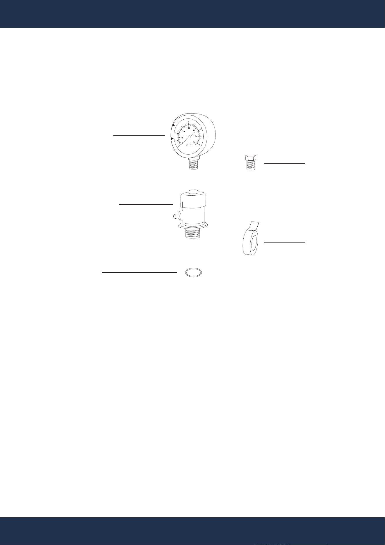
PACKAGING CONTENTS
PRODUCT INFORMATION
PARTS # 1
AIR PRESSURE GAUGE
1 PC(S)
psi
bar
S
T
A
R
T
C
L
E
A
N
F
I
L
T
E
R
PARTS # 5
TEFLON TAPE
1 PC(S)
PARTS # 3
LARGE O-RING
1 PC(S)
PARTS #
2
MANUAL AIR RELIEF VALVE
1 PC(S)
PARTS #
4
VALVE PLUG
1 PC(S)

INSTALLATION
5
INSTALLATION
INSTALLATION INSTRUCTIONS
Step 1: Initial Setup
• Power Off the Pump: Turn off the pump and disconnect it from the power source to elimi-
nate electrical hazards.
• Remove Existing Gauge:
▪ Rotate the valve stem counterclockwise to release air pressure.
▪ Carefully detach the existing air relief valve from the filter tank by rotating the valve
nozzle counterclockwise.
Step 2: New Manual Air Relief Assembly
• Apply Teflon Tape: Wrap two complete turns of Teflon tape counterclockwise around the
thread section of the manual air relief valve, the valve plug, and the pressure gauge to
ensure a secure seal.
• Install O-Ring: Position the O-ring on the thread section of the manual air relief valve.
• Attach Valve Plug: Screw the valve plug into the top of the manual air relief valve securely.
Step 3: New Manual Air Relief Installation
• Locate Installation Point: Identify the threaded hole at the top of the filter tank where the
valve will be installed.
• Install the Valve: Carefully thread the new manual air relief valve clockwise into the identi-
fied hole. Tighten by hand to avoid damaging the tank or valve threads.
Step 4: Air Pressure Gauge Installation
• Remove Valve Plug: Unscrew the valve plug from the top of the manual air relief valve.
• Attach Pressure Gauge: Secure the pressure gauge to the top of the manual air relief valve.

6
DISCLAIMER
DISCLAIMER
PLEASE READ THE FOLLOWING CAREFULLY
The manufacturer and/or distributor have provided the parts list and assembly diagram in this
manual for reference purposes only. They do not make any representation or warranty to the buyer
that they are qualified to make repairs to the product or replace any parts of the product. In fact, the
manufacturer and/or distributor expressly state that all repairs and parts replacements should be
undertaken by certified and licensed technicians, and not by the buyer.
The buyer assumes all risk and liability arising from their repairs to the original product or
replacement parts or arising from their installation of replacement parts. It is strongly advised that
qualified professionals handle any repairs or replacements to ensure safety and proper functioning
of the product. Improper installation and operation may result in injury, property damage, or voiding
of warranty. The manufacturer and/or distributor shall not be held responsible for any accidents,
damages, or malfunctions resulting from the buyer's installation and operation of the product. It is
essential to follow all safety guidelines and recommendations provided in this manual and to seek
professional assistance if unsure about the installation or operation procedures.
CUSTOMER SERVICE
If you have any questions about ordering our pool pumps and replacement parts or pool products,
please feel free to contact us using the following contact information:
Customer Service and Technical Support
Phone: (909) 628-0880
Email: [email protected]
Hours of Operation: Monday – Friday, 9AM – 4PM (CST)
