
ESP-LXD Controller
Installation, Programming & Operation Guide

Symbols
bb
NOTE: Symbol is intended to alert the user to important operating,
functionality or maintenance or installation instructions.
bc
WARNING: Symbol is intended to alert the user to the presence
of electricity within the controller which may constitute a risk of
electronic shock or other hazard.
bd
CAUTION: Symbol is intended to alert the user to important
instructions or conditions that could seriously aect irrigation
eectivity or controller operation.
bg
DIAL: Symbol indicates that the user is required to turn the dial
on the controller to the appropriate setting in order to follow
subsequent instructions as described in that section.
be
REPEAT: Symbol indicates that a repetition of previous steps
or actions may be required in order to continue or complete the
controller programming process.
Safety Information
bc
WARNING: A circuit breaker or cuto switch must be provided
in the xed wiring to isolate the controller.
bc
WARNING: The current date and time on the controller is
retained by a long-life lithium battery, which must be disposed of
in accordance with local regulations.
Regulatory Information
This equipment has been tested and found to comply with the limits
for a Class B digital device, pursuant to Part 15 of the FCC Rules. These
limits are designed to provide reasonable protection against harmful
interference in a residential installation.
This equipment generates, uses, and can radiate radio frequency energy
and, if not installed and used in accordance with the instructions, may
cause harmful interference to radio communications. However, there is
no guarantee that interference will not occur in a particular installation.
If the equipment does cause harmful interference to radio or television
reception, which can be determined by turning the equipment o and
on, the user is encouraged to try to correct the interference by the
following measures:
bl
Reorient or relocate the receiving antenna.
bl
Increase the separation between the equipment and the receiver.
bl
Connect the equipment into an outlet on a circuit dierent from
that to which the receiver is connected.
bl
Consult the dealer or an experienced radio/TV technician for help.
Changes or modications not expressly approved by Rain Bird
Corporation could void the user’s authority to operate the equipment.
This product was FCC certied under test conditions that included the
use of shielded I/O cables and connectors between system components.
To be in compliance with FCC regulations, the user must use shielded
cables and connectors and install them per instructions.
For technical assistance contact Rain Bird at 800 RAINBIRD (1-800-724-6247) U.S. and Canada
Visit us on the web at www.rainbird.com

I
ESP-LXD Controller
Contents
Section A - Introduction & Overview ................... 1
Welcome to Rain Bird ....................................................... 1
ESP-LXD Controller ..........................................................1
Controller Features ..................................................................................1
Controls, Switches and Indicators ....................................................2
2-Wire Path Overview .......................................................3
Star Pattern ..................................................................................................3
Loop Pattern ...............................................................................................4
Decoders ......................................................................................................5
Types of Decoders ...............................................................................5
Field Decoder Addresses ..................................................................5
Basic Operation .........................................................................................6
Programming Overview ................................................... 7
Irrigation Controller Definitions ........................................................7
Programs ..................................................................................................7
Watering Days .......................................................................................7
Watering Start Time ............................................................................7
Station Run Time ..................................................................................7
Programming Guide ...............................................................................7
Fill Out Programming Guide ..........................................................7
Apply Decoder Address Labels .....................................................8
Storing the Programming Guide ..................................................8
Remote Programming ...........................................................................8
Programming Checklist ........................................................................9
Set Up Hardware ..................................................................................9
Set Up Programs ...................................................................................9
Set Up Programs (Optional) ............................................................9
Review Setup .........................................................................................9
Optional Setup ......................................................................................9
AUTO
...............................................................................10
Automatic Operation ..........................................................................10
Alarm Conditions ..................................................................................11
Decoder Address Alarms ...............................................................11
FloWatch
TM
Alarms ............................................................................11
Review Alarm Messages ................................................................11
Resetting the Controller ....................................................................12
Optional Features ...........................................................12
Station Expansion Module (ESP-LXD-SM75) ............................12
Section B - Basic Programming .......................... 13
Set Current Date & Time .................................................13
Program Select Switch ...................................................14
Select Program .......................................................................................14
Setup Wizards .................................................................14
Valve Types Setup .................................................................................14
Master Valves Setup .............................................................................16
Weather Sensors Setup ......................................................................18
Set Up Decoder-Based Weather Sensors ...............................18
Weather Sensors Bypassed/Active Switch ............................19
Local Weather Sensors ...................................................................19
Custom Pause Sensors ...................................................................19
Custom Prevent Sensors ...............................................................19
Station Setup ...........................................................................................20
Flow Sensors Setup ..............................................................................22
Set Up Rain Bird Flow Sensor ......................................................22
Set Up Custom Flow Sensor ........................................................23
Set Watering Start Times ................................................25
Select Days to Water .......................................................26
Station Run Times ...........................................................27

II
ESP-LXD Controller
Section C - System Diagnostics .......................... 29
Test All Stations/Check System ......................................29
Confirm Programs .................................................................................29
Program Summary ...........................................................................29
Review Program .................................................................................30
Program Run Time ............................................................................33
Station Run Time ...............................................................................34
Test All Stations ......................................................................................35
2-Wire Path Diagnostics .....................................................................36
Short Finding ......................................................................................36
Decoder Test ........................................................................................38
Line Survey ...........................................................................................40
Ping Decoders ....................................................................................42
Weather Sensor Status ........................................................................44
Master Valve Status ..............................................................................45
Section D - Advanced Programming .................. 47
Seasonal Adjust %..........................................................47
Adjust Individual Program ................................................................47
Adjust By Month ....................................................................................48
Select Months to Adjust ................................................................48
Select Programs To Adjust ............................................................49
Delay Watering ...............................................................50
Rain Delay .................................................................................................50
Calendar Day Off ...................................................................................51
Water Windows ......................................................................................52
Set Up Water Window .....................................................................52
Watering Cycles ..............................................................53
Watering Cycle Definitions ...............................................................53
Custom, Odd, Odd no 31st, Even ..................................................53
Cyclical Days ............................................................................................55
Station Settings ..............................................................56
Set Up Cycle+Soak
TM
...........................................................................56
Set Up Station Delay ............................................................................57
Set Up SimulStations
TM
......................................................................58
Set SimulStations
TM
for Program ................................................58
Set SimulStations
TM
for Controller .............................................59
Station Sequencing ..............................................................................60
Section E - Options & Special Features .............. 61
Backup and Recall Programs .........................................61
Store Default Programs ......................................................................61
Recall Default Programs .....................................................................62
Delayed Recall ........................................................................................63
Programming Backup Cartridge (PBC-LXD) ..................64
PBC-LXD Features .................................................................................64
Barcode Scanning Feature ................................................................64
Installing a PBC-LXD ............................................................................65
Backup Programs to PBC-LXD .........................................................66
Restore Programs from PBC-LXD...................................................67
Decoder Barcode Scanning ............................................68
Install Barcode Scanning Pen ..........................................................68
Set Up Barcode Scanning Pen ........................................................70
Test Barcode Scanning Pen ..............................................................71
Scan Field Decoder Addresses .......................................................72
Special Features .............................................................74
Set Language ..........................................................................................74
Set Hours Mode .....................................................................................74
NOMV Cycling .........................................................................................75
Section F - Flow Management ............................ 77
Introduction to Flow .......................................................77
FloZones
TM
Overview...........................................................................77
ESP-LXD Flow Management Features .........................................77
FloManager
TM
Overview ................................................................77
FloWatch
TM
Overview ......................................................................77
Set Flow Units .........................................................................................78
FloManager
TM
.................................................................78
Set Up and Use FloManager
TM
.......................................................79
Enable (Or Disable) FloManager
TM
...........................................79
Set Flow Rates Manually ....................................................................80
Set Station Rates................................................................................80
Set FloZone
TM
Rates .........................................................................81

III
ESP-LXD Controller
FloWatch
TM
.....................................................................82
Set Up and Use FloWatch
TM
.............................................................82
Enable (or Disable) FloWatch
TM
.................................................83
SEEF and SELF Settings and Actions ............................................84
Set Up and Configure SEEF and SELF ......................................84
Learn Flow ................................................................................................87
Learn Flow Automatically (All Stations) .................................87
Learn Flow Automatically (Custom Stations) ......................88
View and Clear Flow Alarms .............................................................90
View Station Flow Alarms .............................................................90
View FloZone
TM
Flow Alarms .......................................................91
Clear Flow Alarms .............................................................................92
View Flow Rates .....................................................................................93
View Flow Rates for Stations ........................................................93
View Flow Rates for FloZones
TM
................................................94
View and Clear Flow Logs .................................................................95
View Current Flow .................................................................................96
Clear Flow Rates .....................................................................................97
Section G - Auxiliary Operation ......................... 99
Module Status ................................................................99
Smart Module Status ...........................................................................99
Check Station Module(s) ...............................................................99
Clear Programs .............................................................100
Clear Individual Program ................................................................ 100
Clear All Programs.............................................................................. 101
Restore Defaults .................................................................................. 102
Manual Watering ..........................................................103
Start Station Manually ..................................................................... 103
Start Program Manually .................................................................. 104
MV Water Window.............................................................................. 105
Set Up MV Water Window .......................................................... 105
Manually Opening a MV ............................................................ 107
Test All Stations ................................................................................... 108
OFF ................................................................................110
Adjust Display Contrast ................................................................... 110
Turn Off 2-Wire Path .......................................................................... 110
Close Master Valves ........................................................................... 112
Section H - Installation .................................... 113
Install the Controller ....................................................113
Installation Checklist ........................................................................ 113
Check Box Contents .......................................................................... 113
Select Location for Controller ...................................................... 114
Gather Installation Tools ................................................................. 114
Access Controller Cabinet .............................................................. 115
Open or Remove Controller Front Panel ............................ 115
Mount Controller ................................................................................ 116
Install Modules .................................................................................... 117
Install LXD Decoder Module .................................................... 117
Install Station Expansion Modules ........................................ 118
Connect Field Wiring ....................................................118
Connecting the 2-Wire Cable ....................................................... 118
Connecting Power to the Controller ............................120
Connect Ground Wire ...................................................................... 120
Connect Power Source .................................................................... 120
Complete Installation ...................................................122
Programming Under Battery Power ......................................... 122
Connect Decoders to Field Wiring ................................123
Wire Splices ........................................................................................... 123
Field Decoder Connections........................................................... 124
Master Valves and MV Decoders ................................................. 124
Surge Protection and Grounding ............................................... 125
Install Lightning Surge Protectors (LSP-1s) ....................... 125
Decoder Managed Flow Sensors ................................................ 126
Connect Flow Sensors ................................................................. 126
Decoder Managed Weather Sensors ........................................ 126
Local Weather Sensors ..................................................................... 127
Connect Local Weather Sensors ............................................. 127
Verifying Field Installation ............................................................. 127
Appendix ......................................................... 129
Electrical Requirement Code of Magnetic Solenoid ........ 129
Master Valve and Pump Set-up Tips .......................................... 130
Using a Field Decoder With a Pump Start Relay ............. 130

this page intentionally left blank

1
ESP-LXD Controller
Section A - Introduction & Overview
Welcome to Rain Bird
Thank you for purchasing your new state-of-the-art Rain
Bird ESP-LXD controller.
For over seven decades Rain Bird has led the irrigation industry in
meeting water management needs by providing the highest quality
products and services available.
ESP-LXD Controller
Your new Rain Bird controller is designed to provide years of
highly manageable irrigation control.
The ESP-LXD is an irrigation controller designed for commercial use. It
accommodates up to 50 stations and through the addition of Station
Modules can easily be expanded to address up to 200 total stations.
Controller Features
The ESP-LXD controller has a variety of advanced features to help you
manage water eciently, including:
bl
Flow, power, and priority management
bl
2-Wire and controller-based diagnostics
bl
Large variety of user-congurable irrigation program options to
meet the most demanding irrigation needs while still addressing
municipal mandates and restrictions
bl
Upgrade features including Station Modules, Programming Backup
Cartridge (PBC), IQ Central Control Communication and ET Manager
Cartridges.
bl
Supports one local and three decoder-based sensor inputs.
bl
Outdoor-rated plastic cabinet which can be upgraded to the
optional metal cabinet (LXMM) and pedestal (LXMMPED).
bl
UL and CE certied.

2
ESP-LXD Controller
D
Display
Displays time of day during normal operation; shows commands
during programming; shows active station and remaining run
time during watering
E
Programming Buttons
Press buttons to enter and change program information.
bl
Press and HOLD buttons to accelerate settings for hours,
minutes and seconds, dates or percentages.
F
Alarm Light
Illuminates to indicate various types of alarm conditions. See
Alarm Conditions for more details on how to review and clear
alarms).
Controls, Switches and Indicators
Key operational features of the ESP-LXD Controller front panel:
A
Programming Dial
Used for programming and to turn the controller on and o.
B
Weather Sensors Switch
Set the controller to obey or ignore input from optional sensors.
See Section B, Weather Sensors Setup for more details.
C
Program Select Switch
Select watering Program A, B, C, or D. See Section B, Program
Select Switch for more details.
ESP-LXD Controller Front Panel Features
1
2
3
4
5
6
3
ESP-LXD Controller
2-Wire Path Overview
The ESP-LXD controller with 2-Wire path has some key
advantages over traditionally wired controllers.
In a traditionally wired system, separate wires are required for each
valve which can be no further than a few hundred yards or meters from
the controller.
The ESP-LXD utilizes a 2-Wire electrical path, upon which decoders can
be attached at any location. This allows greater design exibility and
signicantly greater distances to be supported. Valves in a two wire
system can be managed using up to 3.3 miles (5.5 Km) of total wire
path. Two types of 2-Wire path designs are supported:
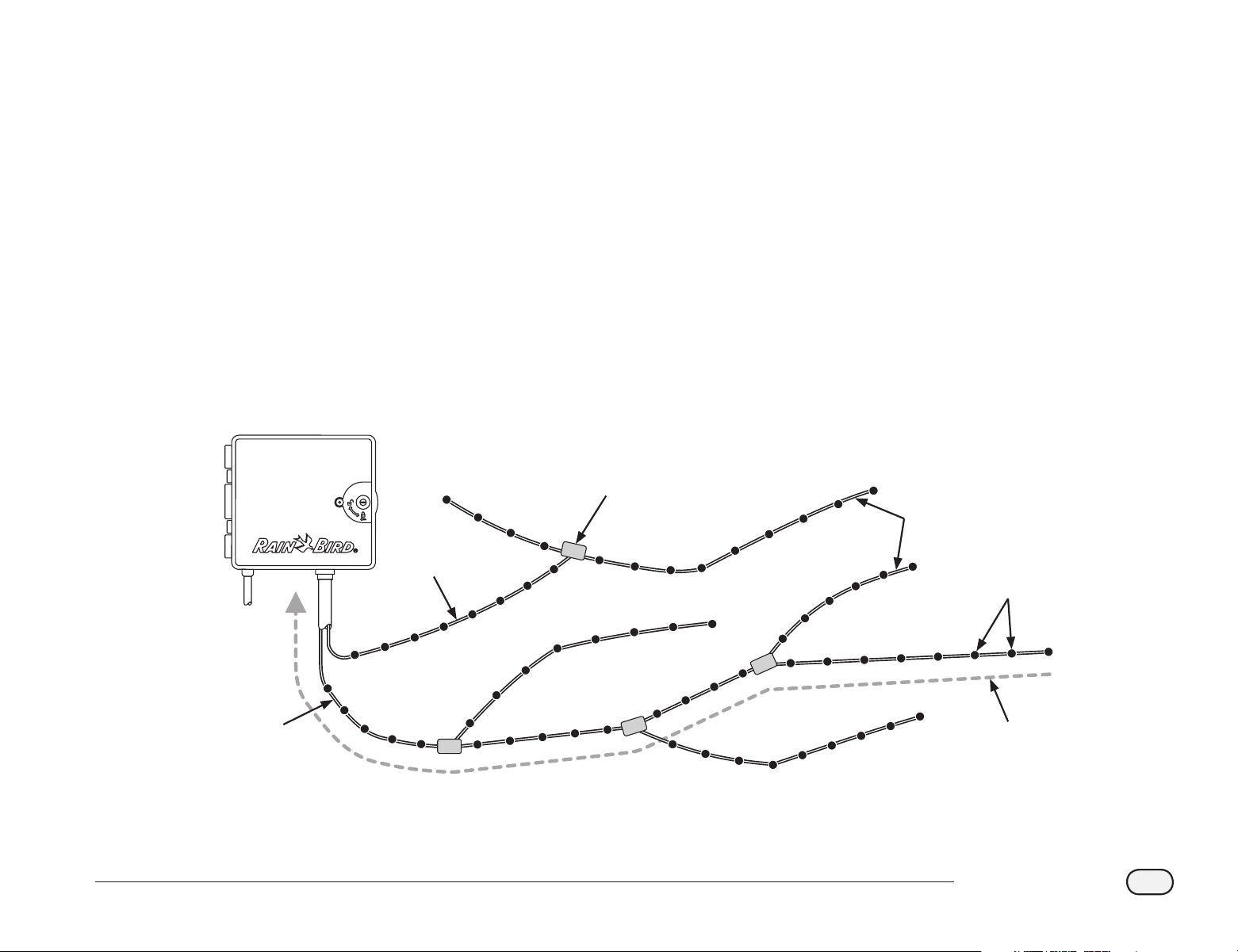
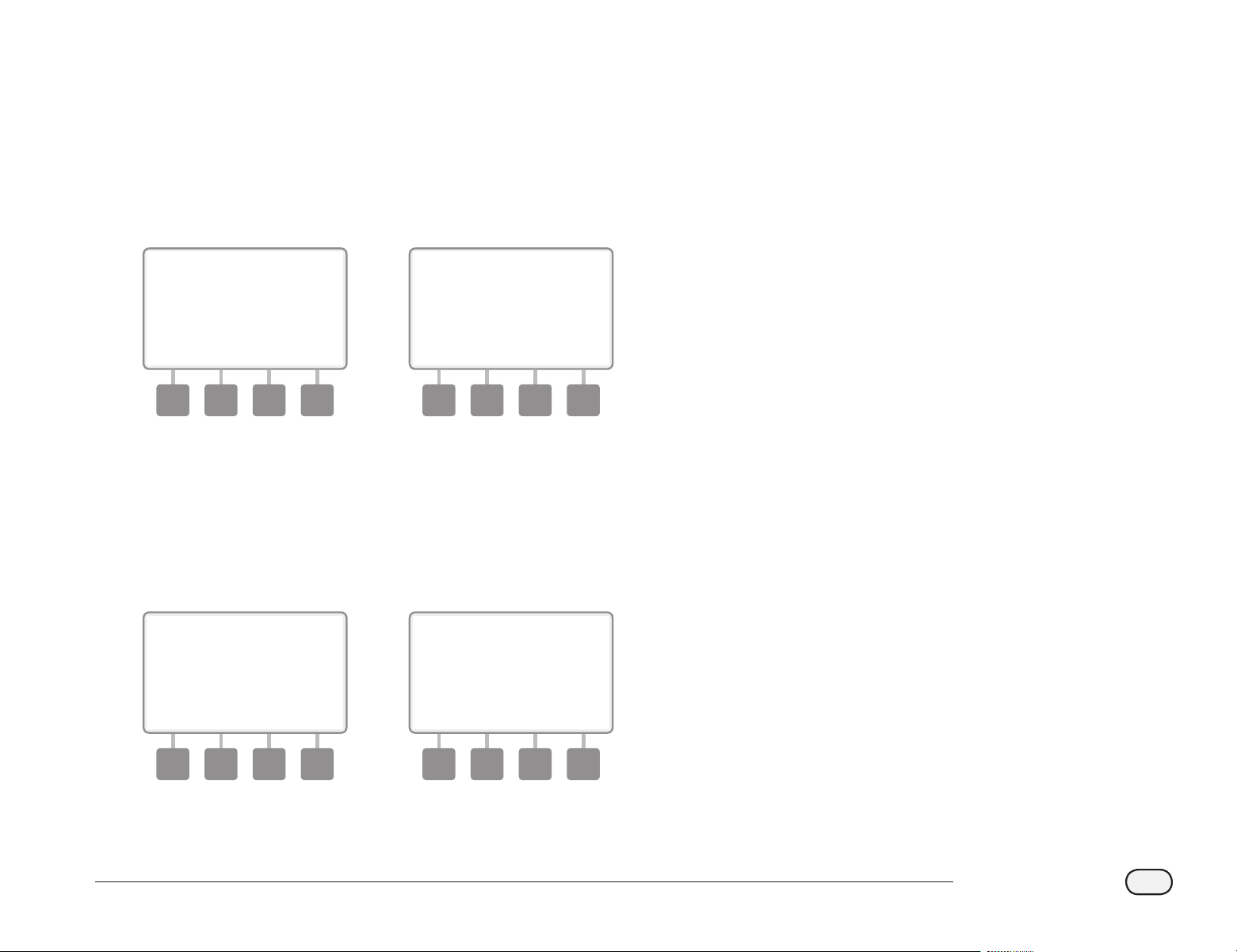
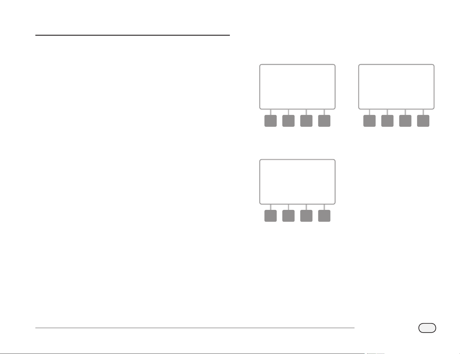
Star Pattern
A Star Pattern allows branching as often as necessary without ever
looping the wire back to the controller.
This generally allows more design exibility but at the expense of some
distance. The distance from the controller to the farthest decoder is
known as the critical path; the greatest distance supported with 14
AWG cable is 1.65 miles (2.66 Km).
bb
NOTE: The ESP-LXD controller has 8 connections for up to four
separate 2-Wire paths.
2-Wire Path Star Pattern Design
Valve Boxes (Typical)
2-Wire splice at branch
take-offs allow easy
breaking of loop for
troubleshooting
Decoders
(Typical)
ESP-LXD Controller
Critical Path
Distance from farthest
decoder back to
controller (maximum
1.65 miles (2.66 Km)
using 14 AWG cable)
First
2-Wire
Path
Second
2-Wire
Path
Branches
4
ESP-LXD Controller
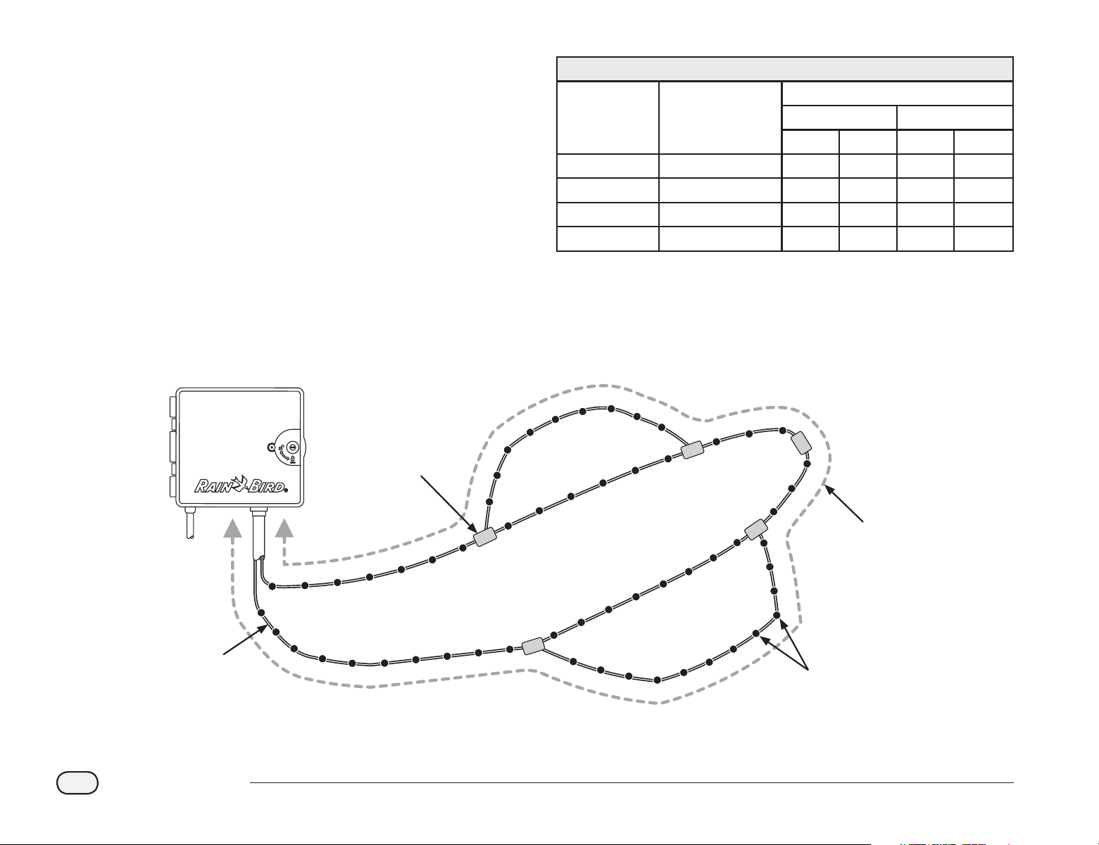
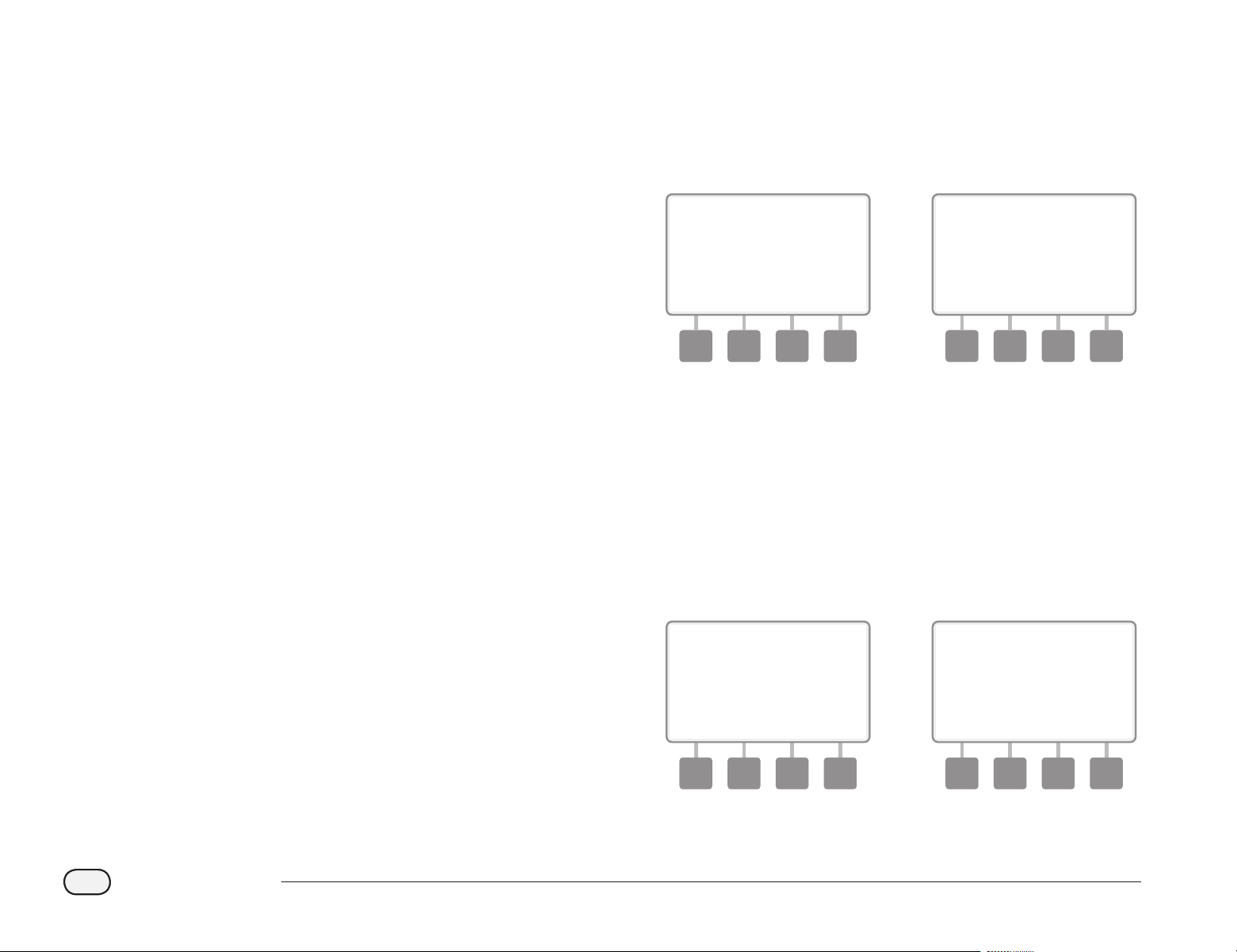
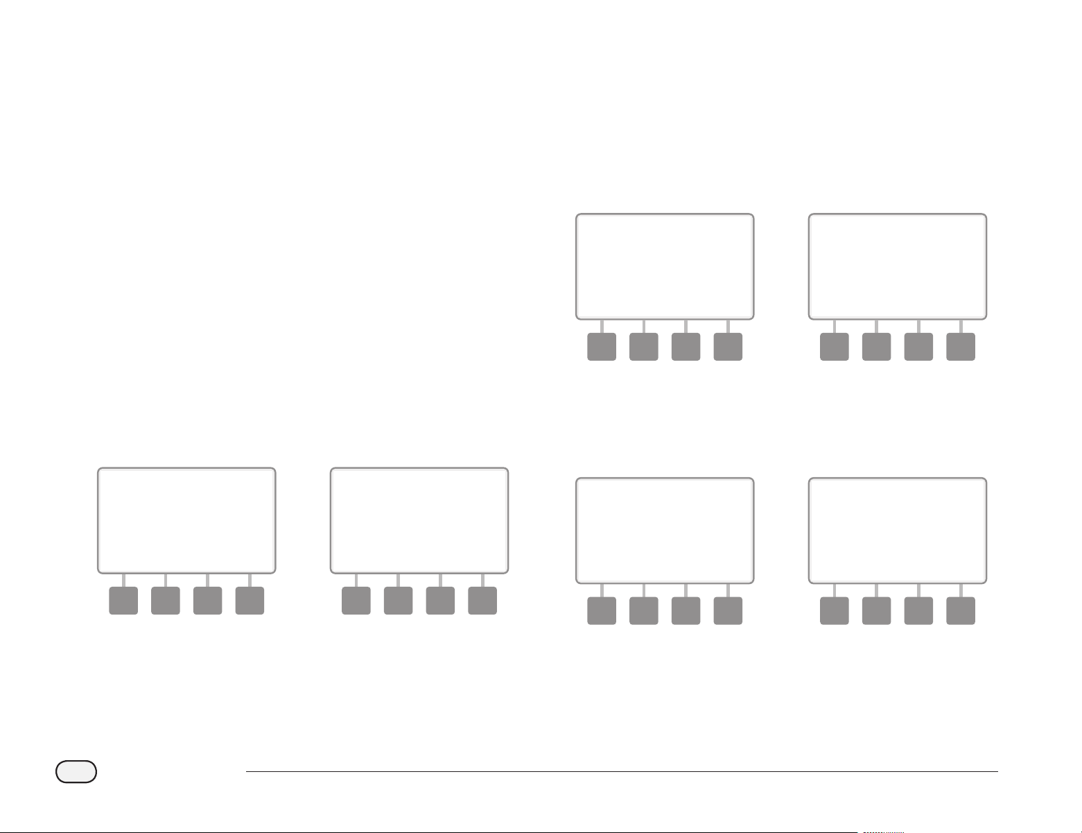
Loop Pattern
A Loop Pattern supports the greatest distance from controller to
decoders.
However the Loop Pattern requires that the 2-Wire path loop back and
return to the controller. The critical path for a Loop design is determined
by calculating the distance around the loop to the farthest decoder
and back to the controller. For both the Star and Loop designs, dierent
distances can be supported with larger gauge cable.
Maximum Critical Path Lengths for 2-Wire Paths
Nominal Wire
Size
Ohms per 1000’ or
Ohms per Km (per
conductor)
Max. Length For Critical Path
Star Loop
Km Miles Km Miles
2.5 mm2 7.5 Ohms/Km 3.00 1.86 12.00 7.46
14 AWG 2.58 Ohms/1000’ 2.66 1.65 10.63 6.61
12 AWG 1.62 Ohms/1000’ 4.23 2.63 16.93 10.52
10 AWG 1.02 Ohms/1000’ 6.72 4.18 26.89 16.71
2-Wire Loop Pattern Design Decoders and Valves
Valve Boxes (Typical)
2-Wire splice at branch
take-offs allow easy
breaking of loop for
troubleshooting
Decoders
(Typical)
ESP-LXD Controller
Critical Path
Total cable length of
the loop’s critical path
(maximum 6.61 miles
(10.63 km) using
14 AWG cable)
Branch #2 Loop
Main Trunk Loop
2-Wire
Loop
Branch #1 Loop
5
ESP-LXD Controller
Decoders
The ESP-LXD controls your irrigation system using decoders.
A decoder is a device which attaches to the 2-Wire path and performs
a task such as opening a valve for irrigation. Some, such as sensor
decoders can be used to provide weather sensor status to the controller.
Typically a controller has several decoders connected, each with one or
more valves attached. Valve outputs at the controller are called stations
and are numbered sequentially. ESP-LXD controller is designed to keep
track of your decoders so that once installed and set up all you have to
do is manage irrigation for the various stations.
Types of Decoders
Field Decoders
Used to open and close valves for irrigation, these are the most
commonly used decoders.
Master Valve (MV) Decoders
Used to open and close master valves. Both Normally Open master
valves (NOMVs) and Normally Closed master valves (NCMVs) are
supported. The ESP-LXD controller can manage up to ve Master Valves.
Weather Sensor Decoders
Used to provide an interface between the weather device and the
controller. The ESP-LXD controller can support up to three weather
sensor decoders.
Local Sensor
The ESP-LXD controller can also interface to a local sensor, such as a rain
shuto device. The local weather sensor connects directly to the ESP-
LXD-M50 module via a separate wired or wireless connection rather
than through a Sensor Decoder connected to the 2-Wire path. The ESP-
LXD controller supports one Local Sensor.
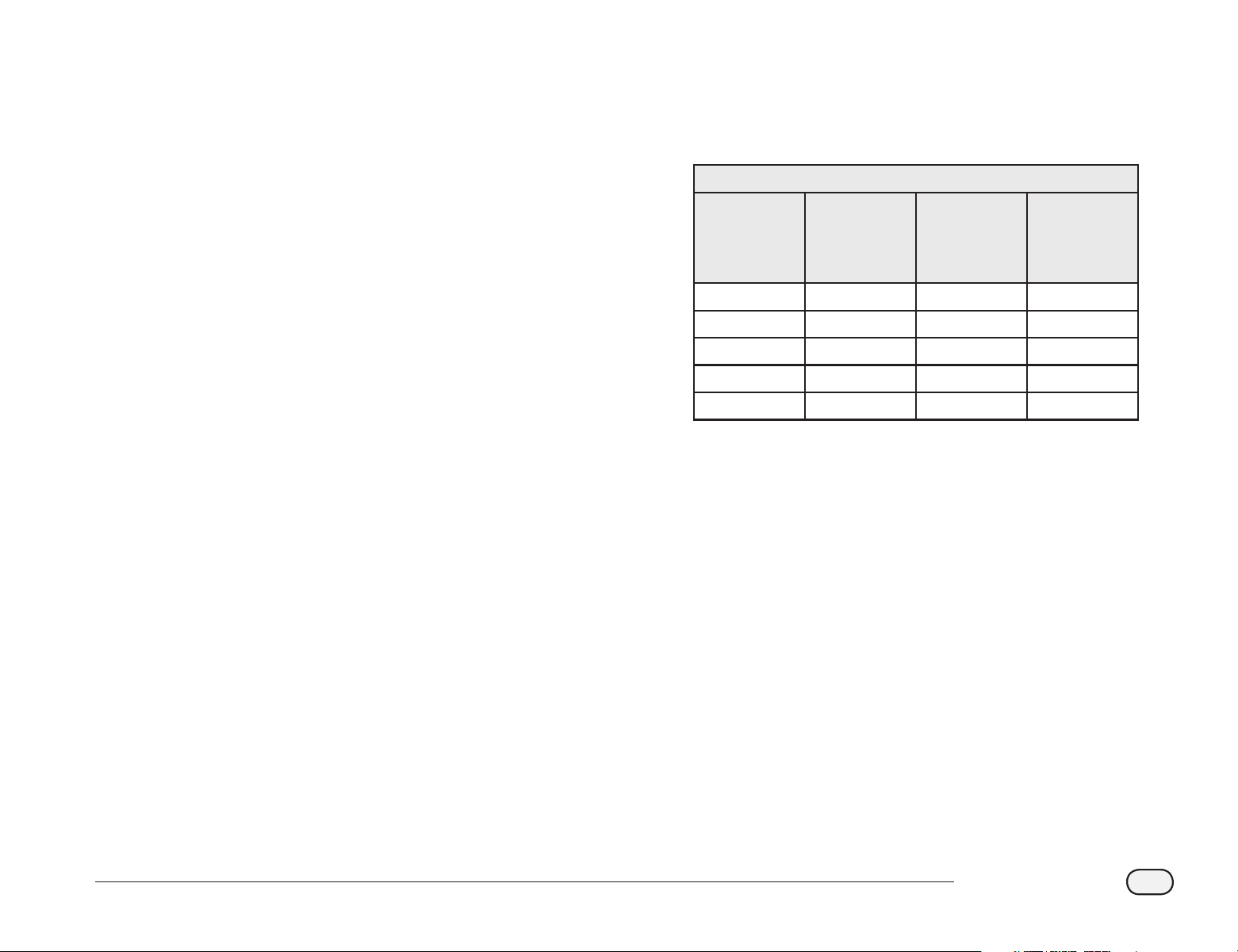
Field Decoder Addresses
Field decoders have unique five digit address identifiers.
Rain Bird Field Decoder Models
Decoder
Model
Number of
Addresses
Per Decoder
Maximum
Number Of
Solenoids
Per Address
Maximum
Addresses
Operating At
Once
FD-101 1 1 1
FD-102 1 2 1
FD-202 2 2 2
FD-401* 4 1 4
FD-601* 6 1 4
* Decoder includes Line Surge Protection.
Some decoders can support more than one valve. For example, an
FD-102
decoder has a single address, but can control 2 dierent
valves. However both valves would always have to open and close
simultaneously since the FD102 only has a single address. An FD-401
could manage four valves, each independently since four addresses are
available.
b
6
ESP-LXD Controller
The ESP-LXD lets you set a delay between stations. For example, if you
set a one minute delay, station 1 will run until nished, followed by
a one minute delay. Then station 2 will run, followed by another one
minute delay, and so on. See Section D, Station Delay for more details.
The order in which stations are selected to operate depends on the
following settings:
bl
Station Sequencing settings
bl
Station priorities
bl
Station run times
bl
Station program assignment
bl
Station ow rate (FloManager)
bl
POC ow rate (FloManager)
bl
SimulStation settings
bb
NOTE: When using Station Sequencing by priorities, set station
priorities higher for stations you want selected earlier in a program
and lower for stations you want selected later in a program.
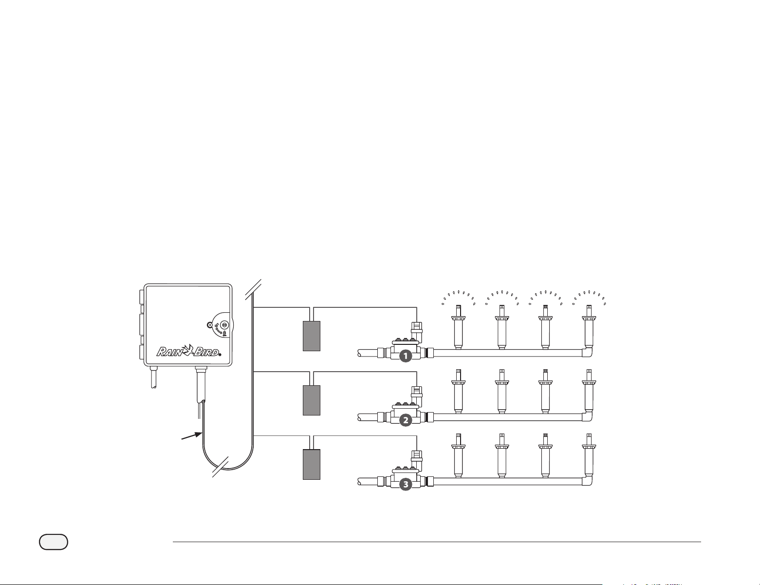
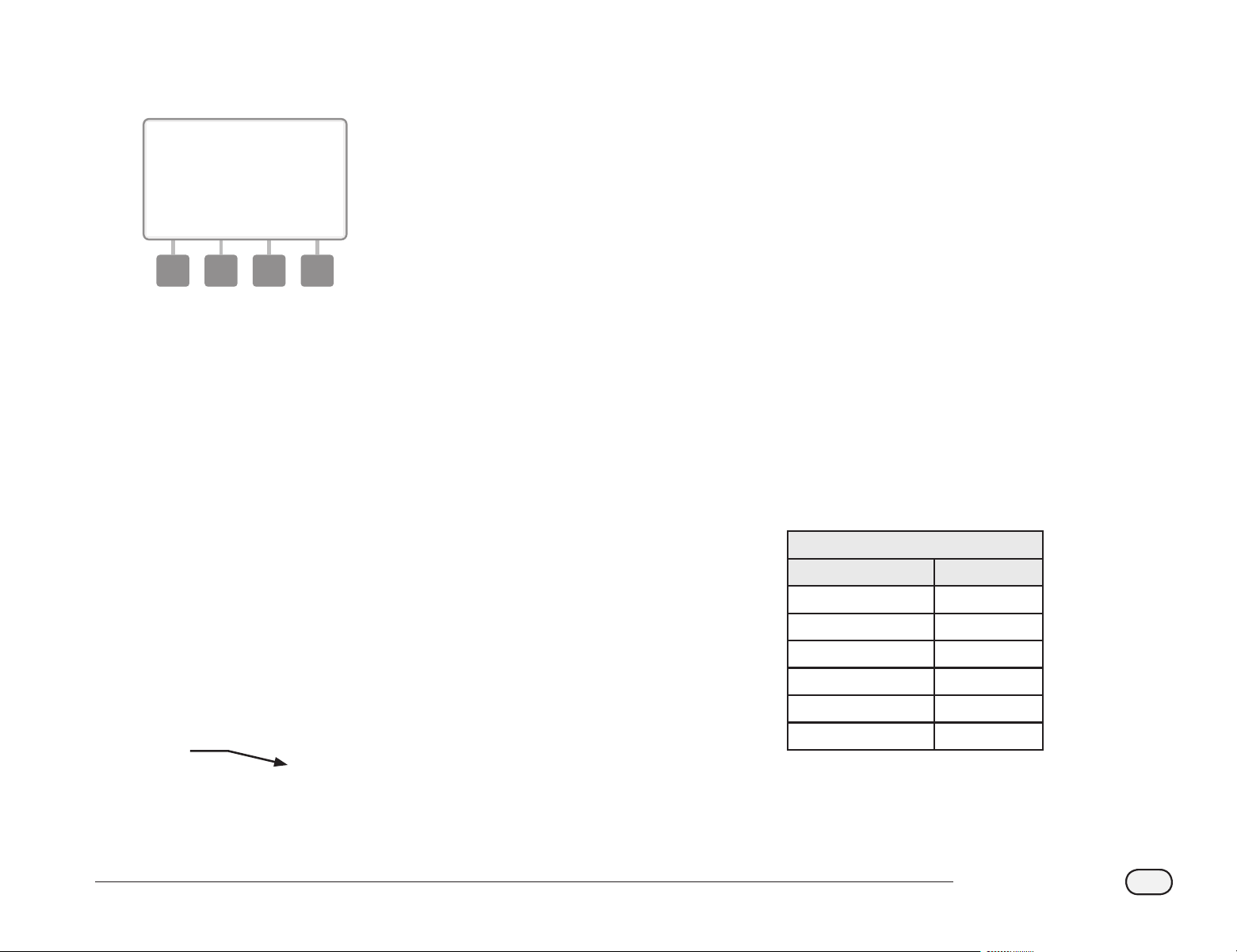
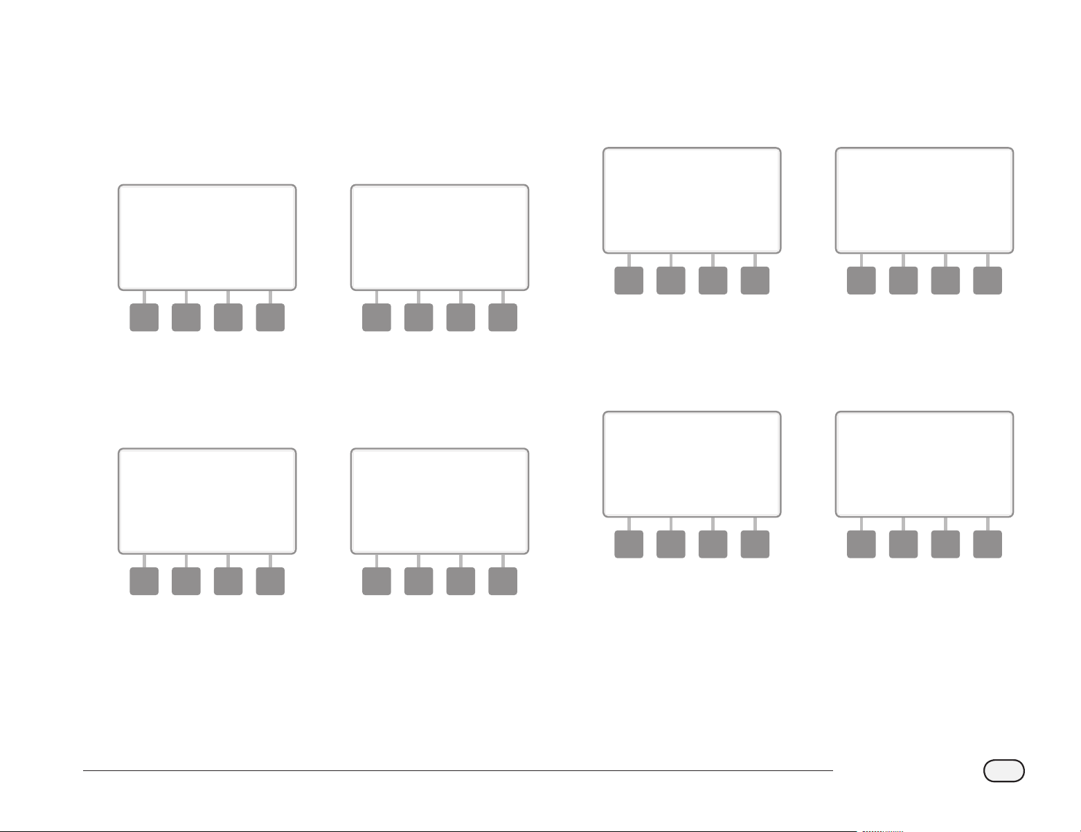
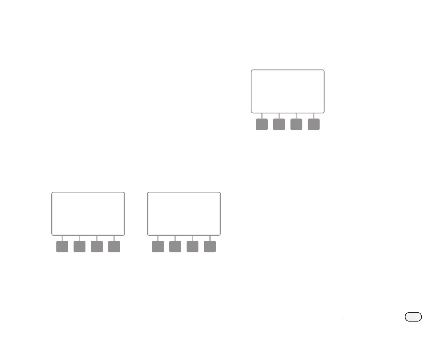
Valves (Stations)
Valves (or stations) operate at times as specified by irrigation programs.
The controller sends signals to the appropriate decoder, powering
the valve solenoid to open or close. When additional stations are
scheduled, another signal is sent to the next decoder and the cycle
continues. For example, the controller sends the rst decoder a signal
to open it’s valve, allowing irrigation. When nished, the controller
signals the decoder to shut o it’s valve and then signals the second
decoder to open the valve. Then when the second station is nished,
the third station will begin watering and so on.
bb
NOTE: The ESP-LXME’s SimulStations feature allows you to operate
multiple stations at the same time. See section D for more details.
bb
NOTE: The ESP-LXD’s Cycle+Soak feature may delay valve
operation. See Section D, Cycle+Soak
for more details.
Typical Decoder and Valve Operation
2-Wire
Path
ESP-LXD Controller
2nd Decoder
3rd Decoder
Valves
1st Decoder
Sprinklers

7
ESP-LXD Controller
Programming Overview
Irrigation Controller Definitions
Programs
The process of telling the controller exactly when and for how long
you want to water. The controller opens and closes the remote control
valves according to a program you set.
Each program contains:
Watering Days
The days of the week or calendar dates on which irrigation is allowed.
For example, specic days such as Monday, Wednesday and Friday
could be designated as your “watering days”. Or else cyclical, such as
every third day, or perhaps only on even or odd days of the month.
Watering Start Time
The time(s) of day that irrigation begins; this is the time that the
rst station in the program begins watering; all other stations in the
program then follow in sequence.
bb
NOTE: The term “start time” refers to the time that a program
starts, not to the time that each individual station begins to run.
Station Run Time
The length of time (in hours and minutes) that each individual station
is programmed to run.
Programming Guide
Before you begin programming, ll out the Programming Guide. See
the Programming Guide instructions for more details.
A
Locate the Programming Guide that came with the ESP-LXD
controller.
1
Fill Out Programming Guide
B
Follow the instructions to enter information about your
system hardware and settings in the appropriate elds on the
Programming Guide.
2
Continued on next page...

8
ESP-LXD Controller
Apply Decoder Address Labels
C
Follow the instructions to apply station, master valve, ow and
weather sensor decoder address labels in the appropriate elds
on the Programming Guide.
3
Storing the Programming Guide
Return the Programming Guide to a permanent, safe location when
you’re nished working with it. We recommend hanging it on the hook
inside the controller cabinet door as shown below.
Remote Programming
The ESP-LXD controller can be programmed while operating under
battery power.
This feature is useful if the controller is installed in an area that is not
easily accessible. It also lets you enter program information before
installing the controller at the job site. See Section H, Programming
Under Battery Power for more details.

9
ESP-LXD Controller
Programming Checklist
When programming the ESP-LXD controller for the rst time, it is
recommended that you complete the following steps in order.
For your convenience a check-o box is provided for each step.
Set Up Hardware
11
Install LXD decoder module ..................................................... Page 117
11
Install SM Station Modules ....................................................... Page 118
11
Fill out Programming Guide (see Programming Guide instructions)
11
Apply decoder address labels (see Programming Guide instructions)
11
Clear program information....................................................... Page 101
11
Set language .................................................................................. Page 74
11
Set time ............................................................................................ Page 13
11
Set date ............................................................................................ Page 13
11
Set up valve types ........................................................................ Page 14
11
Set up master valves ................................................................... Page 16
11
Set up weather sensors (optional) ......................................... Page 18
11
Set up stations and decoders .................................................. Page 20
11
Set up ow sensors (optional) ................................................. Page 22
Set Up Programs
A B C D
14
Select program (A, B, C or D) ............................. Page 14
14
Set watering start times ..................................... Page 25
14
Select watering days * ......................................... Page 26
14
Set station run time(s) ......................................... Page 27
* See Watering Cycles dial position for Odd, Odd31, Even and
Cyclical watering cycles.
Set Up Programs (Optional)
11
Set seasonal adjust ............................................................. Page 47
11
Create a water window ..................................................... Page 52
11
Set up a station delay ........................................................ Page 57
11
Set up Simulstations .......................................................... Page 58
Review Setup
11
Conrm program ......................................................................... Page 29
11
Test stations ................................................................................... Page 35
11
Check 2-Wire setup ..................................................................... Page 36
11
Check installed modules ........................................................... Page 99
Optional Setup
11
Check weather sensor status .......................................... Page 18
11
Schedule calendar days o .............................................. Page 51
11
Create a MV manual water window .............................. Page 105
11
Set Cycle+Soak ..................................................................... Page 56
11
Set ow units ........................................................................ Page 78
11
Activate FloManager .......................................................... Page 78
11
Activate FloWatch ............................................................... Page 82
11
Set up SEEF and SELF actions ......................................... Page 84
11
Set controller to AUTO ............................................................... Page 10
10
ESP-LXD Controller
AUTO
Automatic Operation
The controller will operate automatically with the controller dial set
to AUTO.
If you forget to return the dial to AUTO, the controller will automatically
continue to run programs, unless the dial is set to the OFF position
when all irrigation is canceled.
bg
Turn the controller dial to AUTO.
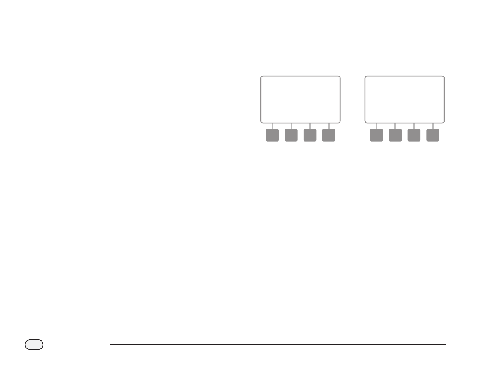
A
The Auto screen is displayed with the current day and time shown.
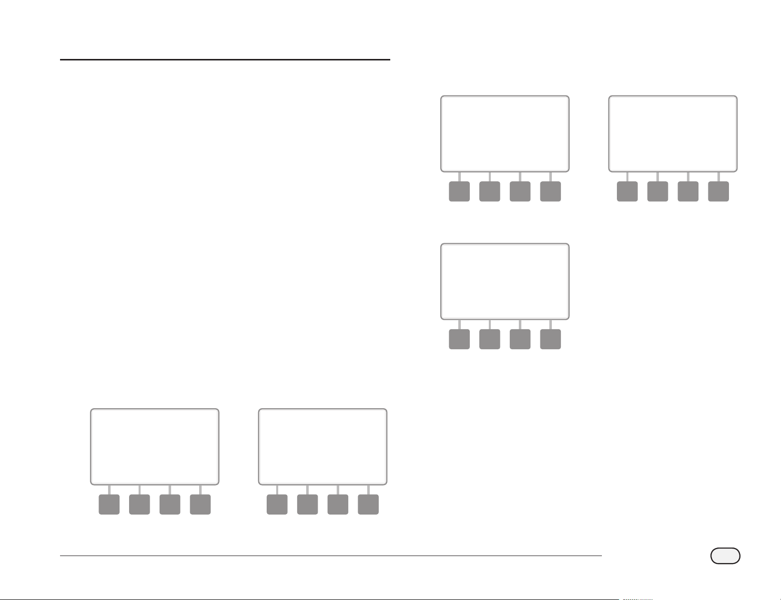
B
When a program is running in AUTO mode, the station number will
display on the screen. Press the + or – buttons to add or subtract
minutes from the run time for the currently running station. To
advance to the next station in a program, press the Adv button.
1 2
bg
To cancel a currently running program, turn the controller dial to
OFF for three seconds and then return the dial to AUTO.
11
ESP-LXD Controller
Alarm Conditions
An alarm condition can occur when programming omissions or other
issues prevent normal irrigation.
Decoder Address Alarms
The controller will alarm if duplicate decoder addresses are entered
for one or more weather sensors, ow sensors or stations. To clear the
alarm, enter a dierent decoder address for one of the decoders. Only
the rst two duplicates will be shown, so you may need to repeat this
process until all duplicate addresses have been cleared.
FloWatch
TM
Alarms
The controller will alarm for certain ow conditions if you have FloWatch
set up. See Section F, Flow Management for more details.
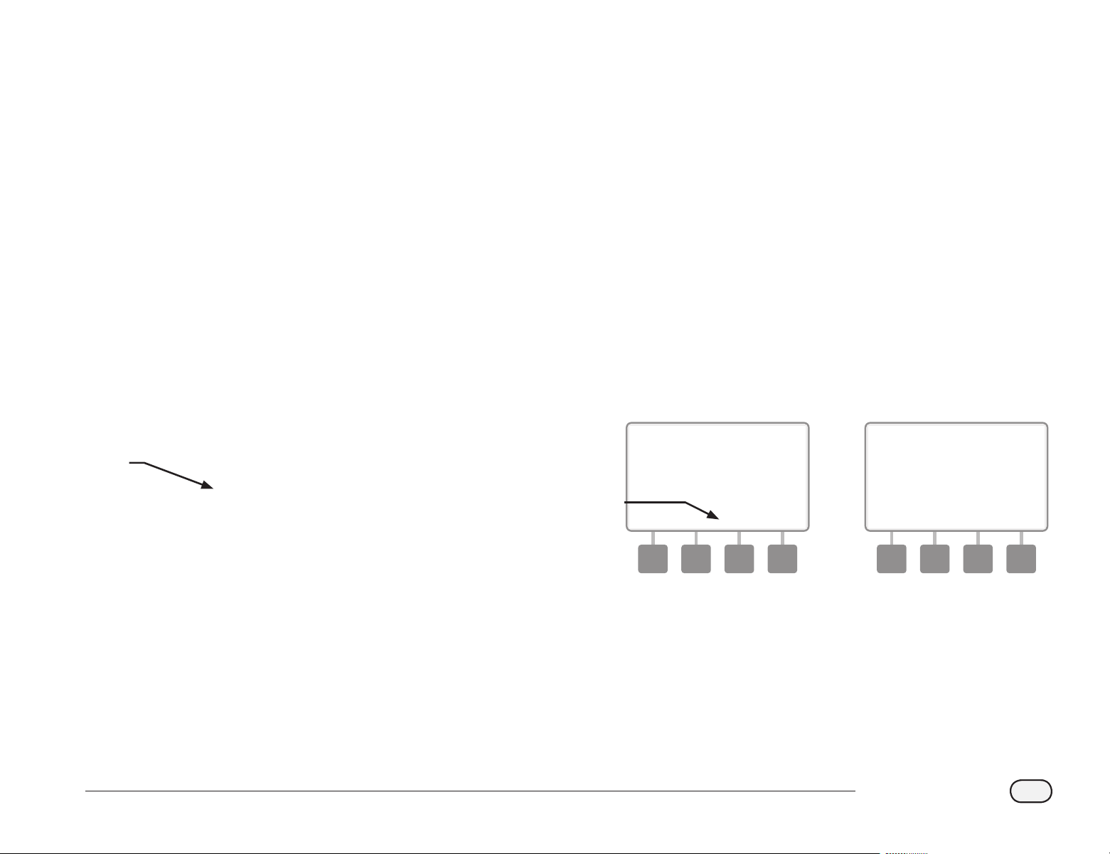
Review Alarm Messages
A
When an alarm condition is detected, the alarm light on the
controller front panel will illuminate.
1
bg
Turn the controller dial to AUTO.
B
When an alarm condition is present, the Alarm button label will be
present on screen. Press the Alarm button to view alarm details.
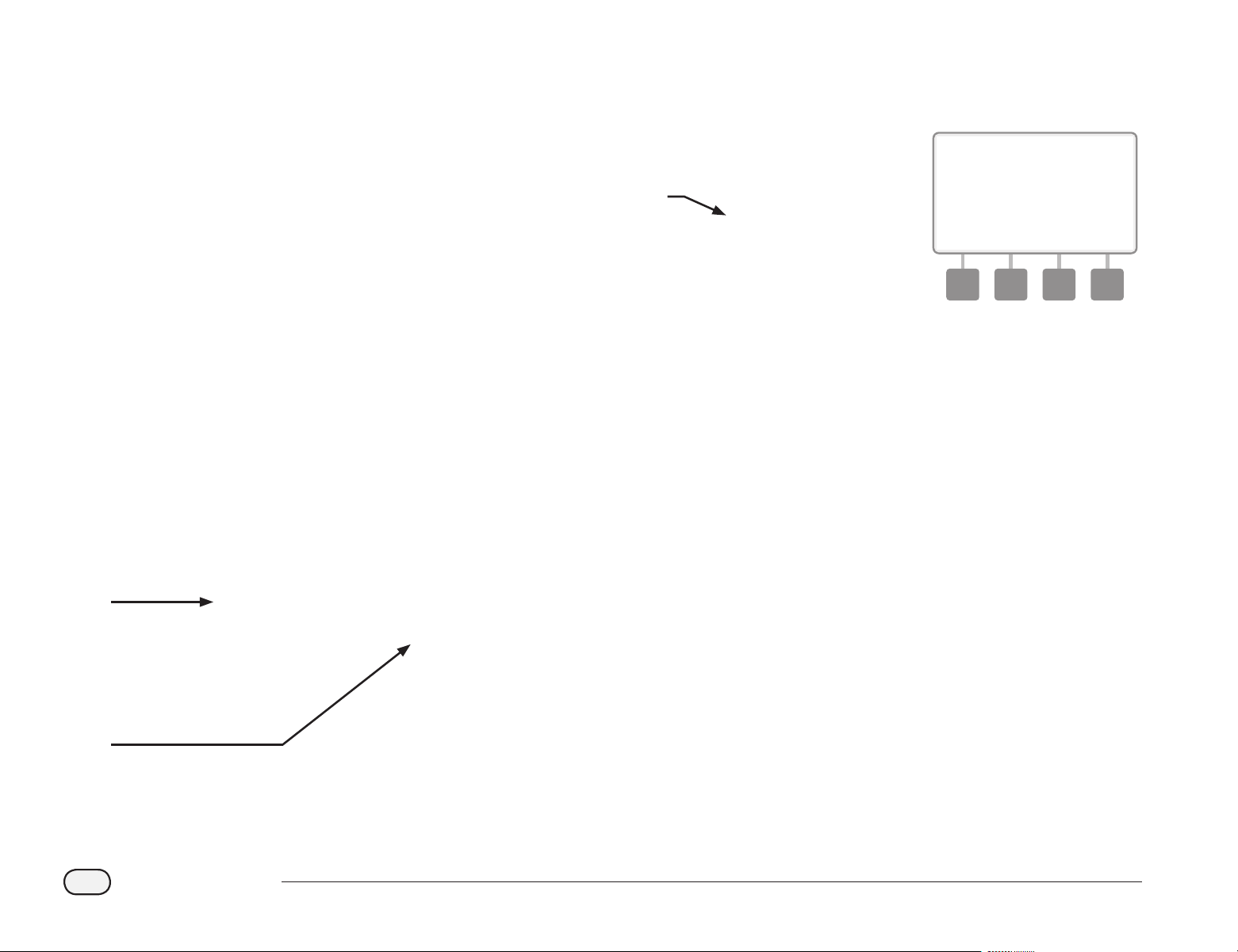
C
Any present alarm conditions will then be displayed. Press the
Next button if necessary, to advance to the next page.
b
c
bb
NOTE: Take the appropriate action to address each alarm
condition. When all alarms have been addressed, the alarm light
on the front panel will no longer be illuminated.
12
ESP-LXD Controller
Resetting the Controller
Sometimes you may want to reset (or reboot) the ESP-LXD controller.
Using the controller’s reset feature does not change or delete the
programs you have loaded into the controller.
bg
Turn the controller dial to AUTO.
A
Open the controller outer cabinet door and inner front panel.
B
Locate the RESET button on the back of the front panel.
1
2
C
Use a pen or pencil to depress the RESET button.
D
The “Rain Bird” screen appears, conrming reset.
3 4
Optional Features
Station Expansion Module (ESP-LXD-SM75)
The ESP-LXD controller comes standard with 50 stations available. This
can easily be expanded by adding one or two optional ESP-LXD-SM75
Station Modules. Each station module adds 75 additional stations to
increase capacity to 125 or 200 stations.
ESP-LXD-SM75 Station Expansion Module
13
ESP-LXD Controller
Section B - Basic Programming
Set Current Date & Time
bg
Turn the controller dial to Set Current Date and Time.
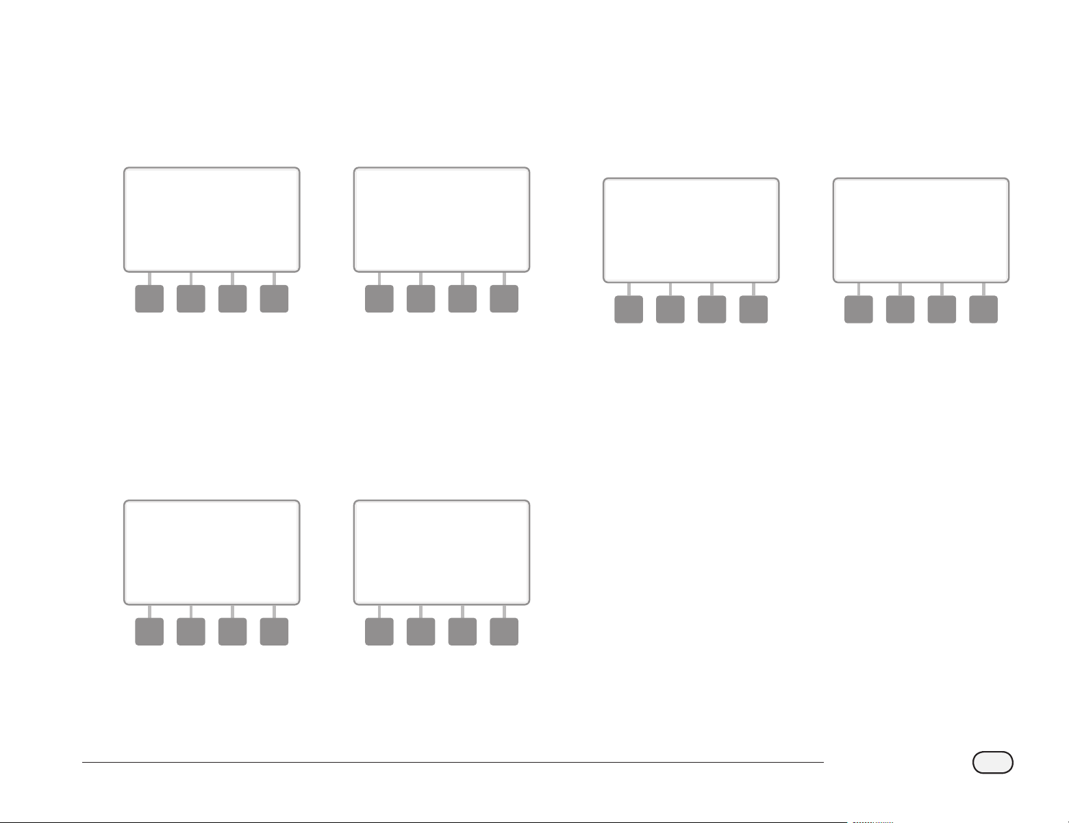
A
The Set Date and Time screen appears. Press the + and – buttons
to set the current hour; then press Next.
bb
NOTE: Be sure to set the hour correctly to either AM or PM.
bl
Press and HOLD buttons to accelerate settings for hours and
minutes.
B
Press the + and – buttons to set the current minute; then press
Next.
1 2
C
Press the + and – buttons to set the current day; then press Next.
D
Press the + and – buttons to set the current month; then press
Next.
3 4
E
Press + and – to set the current year.
5
14
ESP-LXD Controller
Program Select Switch
Always begin programming by setting the Program Select
switch to the desired program.
Four independent Programs, A, B, C and D are available in the ESP-
LXD controller. Multiple programs allow you to set watering schedules
to meet dierent requirements for plant materials, soils, slopes, and
shady or sunny areas. Programs can operate simultaneously with
the only limitation being the number of stations you program to run
simultaneously.
Select Program
On the controller front panel, slide the Program Select switch under
the A, B, C, or D, then begin programming.
Program
Select
Switch
bb
NOTE: When programming the controller, any program-specic
information you enter, such as start times or watering days, will
aect only the selected program.
Setup Wizards
Setup Wizards take you through each step for setting up your
hardware in the ESP-LXD controller.
It’s most eective to use the Setup Wizards in the order they appear
on the screen: Valve Types, Master Valves, Weather Sensors (if present),
Station Setup, and nally Flow Sensors (if present).
Valve Types Setup
The Valve Type Setup Wizard tells the ESP-LXD controller what types
of valves are used by your irrigation system.
Up to ve dierent valve types are supported by ESP-LXD, set up as V1,
V2, V3, V4, and V5.
bb
NOTE: It’s not necessary to set up additional valve types if you’re
only using one or two types of valves at your job site.
bg
Turn the controller dial to Setup Wizards.
15
ESP-LXD Controller
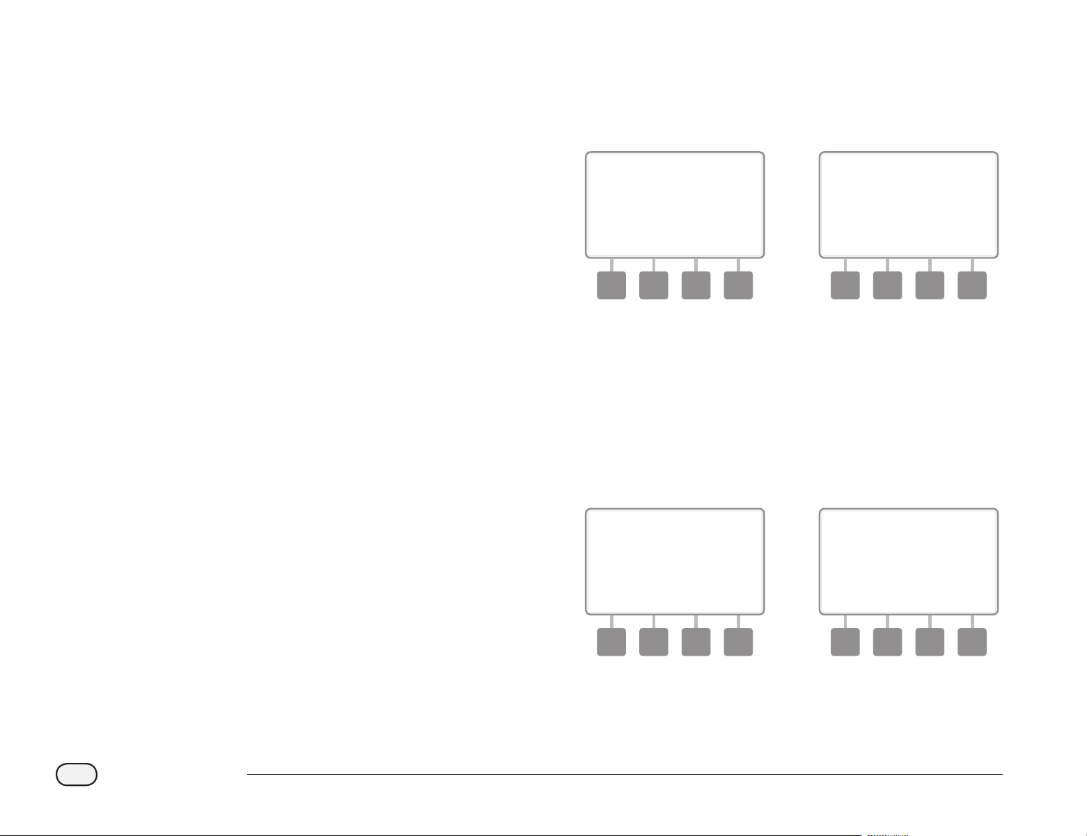
A
The Setup Wizards screen appears with Valve Types selected;
press Next.
B
The Valve Type Setup screen appears. Press the + and – buttons to
choose a name for the rst valve type (V1 is default); then press
Next.
1 2
C
Press the + and – buttons to select the quantity of solenoids your
V1 valve type supports; then press Next.
bb
NOTE: The default quantity of solenoids is 1, however some
decoders can control 2 solenoids.
D
Press the + and – buttons to see the models of Rain Bird valves
which the ESP-LXD supports. Select your valve type (if present);
then press Next.
3 4
bb
NOTE: Rain Bird residential valves (DV and JTV series) are not
compatible with ESP-LXD decoders. Use Rain Bird commercial
valves (PGA, PEB, GB, EFB-CP and BPE series).
E
If you do not see your valve type, select Custom; then press Next.
F
Press the + and – buttons to enter the switch code for your valves.
bb
NOTE: For custom switch codes for non Rain Bird valves, contact
the Rain Bird Global Support Plan group or see values in the
Appendix.
5 6
be
Repeat this process to set up additional valve types.
bb
NOTE: Be sure to note each valve type on your Programming
Guide for future reference.
16
ESP-LXD Controller
Master Valves Setup
The Master Valves Setup Wizard tells the ESP-LXD controller what
types of master valves (MVs) are used by your irrigation system.
The ESP-LXD supports up to 5 Master Valves or pumps. Each MV must
be connected to a Field Decoder and set up in the controller. Both
Normally Open master valves (NOMVs) and Normally Closed master
valves (NCMVs) are supported. Pumps are set up in the controller as
Master Valves. If you are installing a pump, follow the instructions
below, choosing the Pump Start Relay valve type in step 4. For wiring
instructions for a pump please see Appendix B.
bb
NOTE: Follow the previous instructions to set up valve types
before setting up master valves.
bg
Turn the controller dial to Setup Wizards.
A
The Setup Wizards screen appears. Press the Down Arrow button
to select Master Valves; then press Next.
B
The Master Valve Setup screen appears. Press the + and – buttons
to enter the desired MV number; then press Next.
1 2
C
Press the + and – buttons to enter the decoder address, pressing
Next and Back to navigate between the number setting elds;
then press Next.
bb
NOTE: An alarm will show if a duplicate master valve decoder
address is entered for more than one MV. See Section A, Alarm
Conditions for more details.
D
Press the + and – buttons to select the type of valve you’re using
for this MV; then press Next.
3 4
bb
NOTE: Rain Bird residential valves (DV and JTV series) are not
compatible with ESP-LXD decoders. Use Rain Bird commercial
valves (PGA, PEB, GB, EFB-CP and BPE series).
17
ESP-LXD Controller
E
Press the + and – buttons to select Normally Open or Normally
Closed for the MV; then press Next.
bb
NOTE: Standard irrigation valves are Normally Closed (powered
to open). Normally Open valves are specialty valves that are
powered to close.
F
A conrmation screen appears asking you to assign MVs to
FloZones; press Next to continue.
5 6
G
On the FloZone assignment screen, press the + and – buttons to
associate the MV with the appropriate FloZone; then press Next.
bb
NOTE: A FloZone can use more than one MV as it’s source(s), but
an MV can only be assigned to a single FloZone.
H
The Shared MVs screen shows the other MVs associated with the
selected FloZone.
7 8
be
Repeat this process to set up additional master valves. Be sure to
note each MV on your Programming Guide for future reference.
18
ESP-LXD Controller
Weather Sensors Setup
The Weather Sensor Setup Wizard tells the ESP-LXD controller what
types of weather sensors are used by your irrigation system.
Weather sensors are not required for the ESP-LXD controller, but they
increase functionality by allowing you to prevent or pause irrigation
based on changing weather conditions. The ESP-LXD can support up
to three decoder-based weather sensors and one local weather sensor.
See Section H, Weather Sensor Installation for more details.
Set Up Decoder-Based Weather Sensors
bg
Turn the controller dial to Setup Wizards.
A
The Setup Wizards screen appears. Press the Down Arrow button
to select Weather Sensors then press Next.
B
The Weather Sensor Setup screen appears. Press the + and –
buttons to enter the desired weather sensor number; then press
Next.
1 2
C
Press the + and – buttons to enter the decoder address, pressing
Next and Back to navigate between the number setting elds;
then press Next.
bb
NOTE: An alarm will show if a duplicate sensor decoder address
is entered for more than one weather sensor. See Section A, Alarm
Conditions for more details.
D
Press the + and – buttons to select the type of weather sensor.
(Rain, Wind, Freeze and Soil moisture sensors are supported); then
press Next.
3 4
19
ESP-LXD Controller
E
Press the + and – buttons to set the desired settling time; then
press Next.
5
bb
NOTE: Settling time is how long a weather condition must last
before the controller takes action. For example, if a freeze sensor
has a 5 minute settling time then the temperature would have
to remain below the sensor’s threshold set point for 5 minutes
before irrigation is paused. Settling time can be set for immediate
(0 seconds) or up to 10 minutes long.
be
Repeat this process to set up additional weather sensors. Be sure
to note each weather sensor on your Programming Guide for
future reference.
Weather Sensors Bypassed/Active Switch
You can set the controller to ignore or obey input from weather sensors.
The Weather Sensors switch activates or bypasses all installed weather
sensors on your system
F
On the controller front panel, slide the Weather Sensors switch to
Bypassed (to ignore) or Active (to obey).
6
Local Weather Sensors
Follow the manufacturer’s installation instructions. See Section H,
Weather Sensor Installation for more details.
Custom Pause Sensors
When a weather condition becomes true, a Custom Pause sensor will
stop irrigation and also stop the irrigation timer. When the condition
becomes false again, irrigation will start exactly where it left o. For
example, if a station is set to irrigate for 20 minutes but is shut down
by a Pause sensor after only 5 minutes; when the weather condition
becomes false again and after Resume, that station will receive the full
remaining 15 minutes of irrigation left on the timer.
Custom Prevent Sensors
When a weather condition becomes true, a Custom Prevent sensor
will stop irrigation but allow the irrigation timer to continue to run.
When the condition becomes false again, irrigation will resume at the
same time had the weather condition never occurred. For example, if
a station is set to irrigate for 20 minutes but is shut down by a Prevent
sensor after only 5 minutes, if the condition becomes false again after
10 minutes then that station will only receive the remaining 5 minutes
of irrigation left on the timer.
Sensor Types
Type Action
Rain Prevent
Wind Pause
Freeze Pause
Soil Moisture Prevent
Custom Pause Pause
Custom Prevent Prevent

20
ESP-LXD Controller
Station Setup
The Station Setup Wizard tells the ESP-LXD controller how many and
what type of stations are used by your irrigation system.
Each valve within an irrigation system is referred to as a station. Be sure
to note the location of each station on the Programming Guide so they
can be set up correctly in the controller.
The ESP-LXD controller also supports station setup by scanning decoder
barcode labels using the optional Programming Backup Cartridge
(PBC-LXD). See Section E for more details.
bb
NOTE: Before setting up stations, follow the previous instructions
to set up valve types, master valves and weather sensors (if
present).
bg
Turn the controller dial to Setup Wizards.
A
The Setup Wizards screen appears. Press the Down Arrow button
to select Station Setup then press Next.
B
The Station Setup screen appears. Press the + and – buttons to
enter the desired station number; then press Next.
1 2
C
Press the + and – buttons to enter the decoder address, pressing
Next and Back to navigate between the number setting elds;
then press Next.
bb
NOTE: An alarm will show if a duplicate decoder address is
entered for more than one station. See Section A, Alarm Conditions
for more details.
D
Press the + and – buttons to select the type of valve you’re using
for this station; then press Next.
3 4

21
ESP-LXD Controller
bb
NOTE: Station Priorities are only used when Station Sequencing
is set to Sequence by Station Priority. If you’re using the default
Sequence by Station Numbers, then skip the next step by pressing
Next.
E
Press the + and – buttons to set station priority. Each station can
be set to high, medium, low or Non-irrigation. Station priority is
especially important when multiple programs run simultaneously.
The controller will run all high priority stations rst, then all
medium and nally all low priority, regardless of the station’s
program settings.
bb
NOTE: Non-irrigation stations such as fountains and landscape
lighting receive priority to always run, regardless of weather
conditions.
F
The FloZone Assignment screen lets you assign stations to
FloZones if you’re using either the FloWatch or FloManager
features. Press the + and – buttons to see available FloZones, or if
you’re not using FloZones, select zero; then press Next.
5 6
bb
NOTE: If you have already set up your MVs and FloZones, the MV
assignments for the currently selected FloZone will be shown in
the bottom portion of the screen.
G
The Weather Sensor Assignment screen lets you select which
weather sensors a particular station will obey. Press the + and –
buttons to set Y, for weather sensors which that station should
obey, or set N, for sensors which that station should ignore. Press
Next and Back to navigate between the WS elds.
7
bb
NOTE: All weather sensors, both decoder-based and local, can
be turned on (Active) or o (Bypassed) using the Weather Sensors
switch on the controller front panel. See Weather Sensors Setup
for more details.
be
Repeat this process to set up additional stations.
22
ESP-LXD Controller
Flow Sensors Setup
The Flow Sensor Setup Wizard tells the ESP-LXD controller what ow
sensors are used by your irrigation system.
Flow sensors are not required for the ESP-LXD controller, but they add
functionality by alerting you to abnormally high or low ow rates and
even shutting down aected MVs or stations if ow rates exceed set
thresholds. The ESP-LXD can support up to ve ow sensors.
Set Up Rain Bird Flow Sensor
bg
Turn the controller dial to Setup Wizards.
A
The Setup Wizards screen appears. Press the Down Arrow button
to select Flow Sensors; then press Next.
B
The Flow Sensor Setup screen appears. Press the + and – buttons
to enter the desired ow sensor number; then press Next.
1 2
C
Press the + and – buttons to enter the decoder address, pressing
Next and Back to navigate between the number setting elds;
then press Next.
bb
NOTE: An alarm will show if a duplicate sensor decoder address
is entered for more than one ow sensor. See Section A, Alarm
Conditions for more details.
D
Press the + and – buttons to select the Rain Bird ow sensor model
that you’re using.
3 4
E
Press the + and – buttons to enter the MV you wish to assign to
the ow sensor. Each assigned FloZone will be shown below the
MV eld.
5
be
Repeat this process to set up additional ow sensors. Be sure to
note each ow sensor on your Programming Guide for future
reference.
23
ESP-LXD Controller
Set Up Custom Flow Sensor
bg
Turn the controller dial to Setup Wizards.
A
The Setup Wizards screen appears. Press the Down Arrow button
to select Flow Sensors; then press Next.
B
The Flow Sensor Setup screen appears. Press the + and – buttons
to enter the desired ow sensor number; then press Next.
1 2
C
Press the + and – buttons to enter the decoder address, pressing
Next and Back to navigate between the number setting elds;
then press Next.
bb
NOTE: An alarm will show if a duplicate sensor decoder address
is entered for more than one ow sensor. See Section A, Alarm
Conditions for more details.
D
Press the + and – buttons to select Custom; then press Next.
3 4
E
Press the + and – buttons to set the ow sensor K Factor, pressing
Next and Back to navigate between the number setting elds;
then press Next.
F
Press the + and – buttons to set the ow sensor Oset, pressing
Next and Back to navigate between the number setting elds;
then press Next.
5 6

24
ESP-LXD Controller
G
Press the + and – buttons to enter the MV you wish to assign to
the ow sensor. Each assigned FloZone will be shown below the
MV eld.
7
be
Repeat this process to set up additional custom ow sensors. Be
sure to note each ow sensor on your Programming Guide for
future reference.
25
ESP-LXD Controller
Set Watering Start Times
Start times are the time(s) of day that the program begins.
You can assign up to eight Start Times to a single program. Multiple
Start Times allow you to run a program more than once on each day.
For example, if you’re growing new lawn seed, you may want to water
several times a day to keep the seedbed or top dressing damp.
bb
NOTE: Start times apply to the entire program and not just to an
individual station.
bg
Turn the controller dial to Set Watering Start Times.
A
The Set Start Times screen appears. Press the + and – buttons to
set Start Time for the current program; then press Next.
bl
Press and HOLD buttons to accelerate settings for hours and
minutes.
bb
NOTE: If the desired program is not selected, use the Program
Select switch to change it. See Section B, Program Select Switch
for more details.
B
Press the + and – buttons to set the start number (1 through 8).
1 2
be
Change the Program Select switch and repeat this process to set
up additional Watering Start Times for other programs as desired.
bb
NOTE: Cycle+Soak
TM
is an alternative method of dividing the
total Station Run Time into smaller cycle times. If you plan to use
Cycle+Soak, only a single Watering Start Time is required for each
program. See Section D, Cycle+Soak for more details.
26
ESP-LXD Controller
Select Days to Water
Watering Days are the specific days of the week on which
irrigation is allowed to take place.
The ESP-LXD controller can be programmed to irrigate on dierent
days, dates and cycles. Regardless of which Watering Cycle you set,
the controller will only irrigate on the days or dates that you select. For
additional information see Watering Cycles later in this section.
bb
NOTE: The selections you make on the day positions of the
controller dial will carry over to the Watering Cycles day settings
and vice versa.
bg
Turn the controller dial to Mon 1.
A
The Custom screen appears. Press the Allow or Prevent buttons to
choose whether or not to allow irrigation starts to occur for that
day of the week.
bb
NOTE: If the desired program is not selected, use the Program
Select switch to change it. See Section B, Program Select Switch
for more details.
B
Turn the controller dial to Tue 2 and repeat the process.
1 2
be
Repeat this process for all other days of the week in the program.
Then change the Program Select switch and repeat this process to
select Days to Water for other programs as desired.
27
ESP-LXD Controller
Station Run Times
Run Times are the number of minutes (or hours and minutes)
that each station runs.
Once your stations are set up, you will want to assign irrigation Run
Times for each one. Station Run Times are particular to programs; so
typically stations are set for a single program.
bg
Turn the controller dial to Set Station Run Times.
A
The Set Run Times screen appears. Press the + and – buttons to
enter the station to program; then press Next.
bb
NOTE: If the desired program is not selected, use the Program
Select switch to change it. See Section B, Program Select Switch
for more details.
B
Press the + and – buttons to set the Station Run Time. Range can
be from 00 hours, 00 minutes (no Run Time) up to 24:00 hours.
bl
Press and HOLD buttons to accelerate settings for hours and
minutes.
1 2
be
Change the Program Select switch and repeat this process to set
up additional Station Run Times for other programs as desired.
bb
NOTE: Seasonal Adjust % adjustments will adjust the Station Run
Time down to the second. For example, if the Run Time is set for 1
minute and the Seasonal Adjust % is set to 50% then the adjusted
Run Time equals 30 seconds.

28
ESP-LXD Controller
this page intentionally left blank
29
ESP-LXD Controller
Section C - System Diagnostics
Test All Stations/Check System
Review and confirm scheduled irrigation Programs, Program
Run Times and Station Run Times.
Confirm Programs
The ESP-LXD controller can make calculations and provide feedback on
Start Times and total Run Times for programs and stations.
Program Summary
Review program information for all programs:
bg
Turn the controller dial to Test All stations/Check System.
A
The System Diagnostics screen appears with Conrm Programs
selected; press Next.
B
The Conrm Programs screen appears with Program Summary
selected; press Next.
1 2
C
The Program Summary screen appears, providing a summary of
Run Times, Start Times and water days for all programs.
3
bb
NOTE: In the above example, Program A will run because it has
Station Run Times, Start Times and Watering Days all programmed,
as indicated by the “Y” in each column for PGM A.
Program B however will not run as it is missing both the Start Time
and Water Days programming, as indicated by the “N” in each of
those columns for PGM B. Programs C and D will not run since
both lack Station Run Times, Start Times and Watering Days.
30
ESP-LXD Controller
Review Program
Review program information for a station:
bg
Turn the controller dial to Test All stations/Check System.
A
The System Diagnostics screen appears with Conrm Programs
selected; press Next.
B
The Conrm Programs screen appears. Press the Down Arrow
button to select Review Program; then press Next.
a b
C
The Watering Start Times review screen appears with start times
displayed for the currently selected program. Press Next.
bb
NOTE: If the desired program is not selected, use the Program
Select switch to change it. See Section B, Program Select Switch
for more details.
D
The Watering Day Cycle review screen appears with the current
watering day cycle displayed. Press Next.
c d
E
The Watering Starts Allowed On review screen appears with
allowed watering days displayed. Press Next.
F
The Run Times review screen appears with run times for each
station displayed. Press Next.
e f
31
ESP-LXD Controller
G
The Seasonal Adjust review screen appears with seasonal
adjustment percentage displayed. Press Next.
H
The Seasonal Adjust by Month review screen appears with seasonal
adjustment percentage displayed for the rst allowed month.
Press the + and – buttons to see Seasonal Adjust percentage for
other months as desired; then press Next.
g h
I
The Rain Delay review screen appears with number of days
remaining until next watering date displayed. Press Next.
J
The Calendar Day O review screen appears with all selected
calendar days o displayed. Press Next.
i j
K
The Station Delay review screen appears with delay time between
stations displayed. Press Next.
L
The Cycle+Soak Minutes review screen appears with the
Cycle+Soak times for each station displayed. Press Next.
k l
M
The Master Valve Assignment review screen appears with MV and
associated FloZone information displayed. Press Next.
N
The Weather Sensor Assignment review screen appears with
stations that use sensor override displayed. Press Next.
m n
32
ESP-LXD Controller
O
The Water Window review screen appears with water window
open time, close time and duration displayed. Press Next.
P
The Maximum Number of SimulStations for program review
screen appears with the maximum number of stations that can
operate simultaneously for that program are displayed. Press
Next.
o p
Q
The Maximum Number of SimulStations for controller review
screen appears with the maximum number of stations that can
operate simultaneously for that controller are displayed. Press
Next.
R
The Backup Programs review screen appears with the Contractor
Default backup program status displayed. Press Next.
q r
33
ESP-LXD Controller
Program Run Time
Review total Run Time for an individual program:
bg
Turn the controller dial to Test All stations/Check System.
A
The System Diagnostics screen appears with Conrm Programs
selected; press Next.
B
The Conrm Programs screen appears. Press the Down Arrow
button to select Program Run Time; then press Next.
1 2
C
The Total Run Time screen appears and total Run Time is displayed
for the currently selected program.
bb
NOTE: If the desired program is not selected, use the Program
Select switch to change it. See Section B, Program Select Switch
for more details.
3
bb
NOTE: For stations set up for Cycle+Soak, the Cycle Time (when
irrigation is occurring) will be included in Program Run Time
calculations but Soak times will NOT be included. See Section D,
Cycle+Soak, for more details.
be
Change the Program Select switch and repeat this process to
review and conrm Program Run Times for other programs as
desired.
34
ESP-LXD Controller
Station Run Time
Review total Run Time for all stations:
bg
Turn the controller dial to Test All stations/Check System.
A
The System Diagnostics screen appears with Conrm Programs
selected; press Next.
B
The Conrm Programs screen appears. Press the Down Arrow
button to select Station Run Time; then press Next.
1 2
C
The Sta Run Time Per Day screen appears with total Run Time
displayed for the currently selected station in all four programs.
For programs where a particular station is not used no runtime
will show.
D
Press the + and – buttons to advance and see additional stations.
3 4
bb
NOTE: Soak times for stations set up with Cycle+Soak
are not
included in the Station Run Time calculations. See Section D,
Cycle+Soak for more details.
35
ESP-LXD Controller
Test All Stations
You can test all stations connected to your controller by running each
of them in station number sequence.
Sometimes this is useful after installation, for general maintenance or
as a rst step in troubleshooting your system.
bb
NOTE: Only stations with programmed run times are included in
the Test All Stations operation.
bg
Turn the controller dial to Test All stations/Check System.
A
The System Diagnostics screen appears. Press the Down Arrow
button to select Test All stations; then press Next.
B
The Test All stations screen appears. Press the + and – buttons to
adjust the Test Run Time (adjustable from 1 to 10 minutes) per
station; then press Run.
1 2
C
A conrmation screen appears.
D
Once Run is pressed, stations can be monitored and advanced by
turning the dial to the AUTO position and using the Adv button.
Press the + and – buttons to increase or decrease Run Time
minutes for the current station.
3 4

36
ESP-LXD Controller
2-Wire Path Diagnostics
Although nding the exact location of issues in the eld often requires
some amount of in-the-eld troubleshooting with a clamp meter, the
controller has some built-in features to help you narrow down the
possible issues.
Before beginning 2-Wire path diagnostics, it may be helpful to take the
following steps to eliminate possible other causes:
1. Review and Confirm Programs to check station priorities.
If a suspect station isn’t watering as scheduled, the underlying
issue could be programming-related. The ESP-LXD controller
irrigates based on the station priorities. If multiple programs are
running, higher priority stations will irrigate prior to medium
priority stations, and medium priority stations will irrigate prior to
lower priority stations. See Section B, Station Setup and Conrm
Programs for more details.
2. Run a Test All Stations check to ensure valves are working properly.
The Test All Stations manual test will take priority above pre-
programmed irrigation and allow you to determine which stations
are working properly. See Test All Stations for more details.
Short Finding
The ESP-LXD controller can quickly determine if shorts are present on
the two-wire path.
bg
Turn the controller dial to Test All stations/Check System.
A
The System Diagnostics screen appears. Press the Down Arrow
button to select 2-Wire Diagnostics; then press Next.
B
The 2-Wire Diagnostics screen appears with Short Finding
selected; press Next.
1 2
37
ESP-LXD Controller
C
The Short Finding Mode screen will appear. Press the On button
to begin the Short Finding process.
D
A conrmation screen appears to warn that irrigation will be
disabled during the Short Finding process. Press and hold Yes to
proceed with Short Finding.
3 4
E
A conrmation screen appears, stating that irrigation has been
disabled.
F
A second conrmation screen appears showing that Short Finding
is now On and in progress.
5 6
bb
NOTE: Use a clamp meter to isolate and repair shorts in the
two-wire path. Once repairs are nished, be sure to return to the
controller and turn the dial to exit short nding mode. Irrigation
can not occur until short nding mode has been cancelled.
38
ESP-LXD Controller
Decoder Test
The ESP-LXD controller may be able to provide specic information
on particular decoders.
bg
Turn the controller dial to Test All stations/Check System.
A
The System Diagnostics screen appears. Press the Down Arrow
button to select 2-Wire Diagnostics; then press Next.
B
The 2-Wire Diagnostics screen appears. Press the Down Arrow
button to select station Decoder Test; then press Next.
1 2
C
A conrmation screen appears; press Start.
D
A second conrmation screen appears to conrm the Decoder
Test is In Progress.
3 4
E
The Decoder Test Result screen appears. If no issues are found, the
screen will display a No Issues Found message; press Back.
F
If the controller found issues with one or more decoders, the
information will be displayed. If multiple issues are found, this
may require more than a single screen. Press the Next button to
continue through the issue screens, noting the issues as you go.
5 6

39
ESP-LXD Controller
this page intentionally left blank
40
ESP-LXD Controller
Line Survey
If you determine that one or more stations are not working properly,
then before going into the eld to address the issue you can take steps
at the controller starting with a Line Survey.
Calculate System Amperage
For the Line Survey it’s helpful to know what the total (approximate)
amperage for your system should be. This can be estimated using the
following formula:
System Amperage Calculation
Quantity of single address station decoders X 0.5 mA
+ Quantity of multiple address station decoders X 1.0 mA
+ Quantity of active decoders X 17.5 mA
+ Quantity of other SD210 decoders X 8.0 mA
= Approximate total system amperage (in mA)
* Single address station decoders include the FD-101 & FD-102 decoders
** Multiple address station decoders include the FD-202, FD-401 & FD-601 decoders
Run a Line Survey
Once you have calculated the approximate amperage for your system,
use the following steps to perform a line survey for your system:
bg
Turn the controller dial to Test All stations/Check System.
A
The System Diagnostics screen appears. Press the Down Arrow
button to select 2-Wire Diagnostics; then press Next.
B
The 2-Wire Diagnostics screen appears. Press the Down Arrow
button to select Line Survey; then press Next.
1 2

41
ESP-LXD Controller
C
The Line Survey results will be displayed on a single screen.
3
Interpreting Line Survey Results
A and B represent the two phases of the 2-Wire control system (not
the two wires in the 2-Wire path). The Voltage1 reading for a normal
healthy system is typically in the +14.0 to + 16.0 range for both A and
B. The Voltage2 reading is typically in the -20.0 to -21.0 range for both
A and B. The Voltage1 reading should be approximately equal for A and
B, and the Voltage2 reading should also be approximately equal for A
and B.
If the Voltage1 or Voltage2 readings are 0.0 for either A or B, then one of
the wires on the 2-Wire path are probably shorted to ground.
Milliamperage (mA) varies with the number of decoders installed on
your system and should be approximately equal to the amperage
calculations detailed above for both A and B.
Three ags also appear below the voltage and amperage readings. For
a normal healthy system the ags should typically read OK; abnormal
readings will cause the ag to change to Not OK.
If the temperature ag reads Not OK, discontinue irrigation and allow
your system to cool for an hour or more before repeating the line survey.
If the Current or Overload ags read Not OK, short circuits within your
2-Wire path are typically to blame. However, a Not OK Current ag can
also be due to one or more miscongured decoders, and a Not OK
Overload ag can be caused by a dead short.
If any of the Line Survey results are irregular, it’s best to attempt to
carefully check the 2-Wire path for short circuits and rerun the test.
If you have checked your 2-Wire path and believe it to be in good
condition, checking specic decoders can often help identify specic
issues (see Ping Decoders below).
42
ESP-LXD Controller
Ping Decoders
The ESP-LXD controller can provide detailed information on a specic
decoder.
This can be helpful to narrow a repair trip into the eld to one decoder
or a set of decoders on a particular branch of the two wire path. You can
ping a Station decoder, MV decoder or Sensor decoder. Interpretation
of the results is essentially the same for station and MV decoders.
Ping Station or MV Decoder
bg
Turn the controller dial to Test All stations/Check System.
A
The System Diagnostics screen appears. Press the Down Arrow
button to select 2-Wire Diagnostics; then press Next.
B
The 2-Wire Diagnostics screen appears. Press the Down Arrow
button to select Ping Decoders; then press Next.
1 2
C
The Ping Decoder screen appears with Station Decoder selected.
Press Next to ping a Station decoder (or else press the Down
Arrow button to select MV Decoder); then press Next.
D
The Ping Station (or MV) Decoder screen appears. Press the + and
– buttons to select the desired Station (or MV); then press Ping.
3 4
E
The controller will ping the selected decoder and report;
amperage Prior to the ping, plus In-Rush and Holding current, all
in milliamps.
5
Interpreting Ping Results
bl
The Prior amperage is based on line current for your system and
should be about the same as the previously Calculated System
Amperage.
bl
The In-Rush current reading is typically less than 200 mA. A reading
of 100 mA or less typically indicates an open output, often caused
by a poor connection from the solenoid to the valve.
43
ESP-LXD Controller
bl
The Holding current is typically 10 mA or less. A reading of 50 mA or
greater typically indicates a shorted decoder output.
Ping Sensor Decoder
bg
Turn the controller dial to Test All stations/Check System.
A
The System Diagnostics screen appears. Press the Down Arrow
button to select 2-Wire Diagnostics; then press Next.
B
The 2-Wire Diagnostics screen appears. Press the Down Arrow
button to select Ping Decoders; then press Next.
1 2
C
The Ping Decoder screen appears. Press the Down Arrow button
to select Sensor Decoder; then press Next.
D
The Ping Sensor Decoder screen appears. Press the + and –
buttons to select the desired Sensor; then press Ping.
3 4
E
The controller will ping the selected sensor decoder and report
the D-Level and Reading. Typically these will show as OK. If a Not
OK reading is reported, check the connections to that sensor
decoder or replace it.
5
44
ESP-LXD Controller
Weather Sensor Status
bg
Turn the controller dial to Test All stations/Check System.
A
The System Diagnostics screen appears. Press the Down Arrow
button to select Wthr Sensor Status; then press Next.
B
The Weather Sensor Status screen appears, showing installed
weather sensors and their current status.
1 2
Each sensor will display one of ve status conditions:
a. Monitoring - sensor is active monitoring current weather
conditions.
b. <Inactive> installation has not been completed or the sensor is
not linked to any stations.
c. PAUSING - current weather condition has caused the sensor to
pause irrigation.
d. PREVENTING - current weather condition has caused the sensor
to prevent irrigation.
e. BYPASSED - sensor switch is in the Bypassed position and the
sensor is not monitoring current weather conditions.
bb
NOTE: If current weather conditions are sucient for a weather
sensor to prevent or pause irrigation, then a message appears on
the Auto screen. This is not considered an alarm, so the controller
alarm light will not illuminate.
45
ESP-LXD Controller
Master Valve Status
bg
Turn the controller dial to Test All stations/Check System.
A
The System Diagnostics screen appears. Press the Down Arrow
button to select Wthr Sensor Status; then press Next.
B
The MV Status screen appears, showing installed master valves
and their current status.
1 2

46
ESP-LXD Controller
this page intentionally left blank
47
ESP-LXD Controller
Section D - Advanced Programming
The ESP-LXD controller has a wide variety of advanced but
easy-to-use features designed to simplify irrigation.
Seasonal Adjust %
Seasonal Adjust % allows you to use the heaviest irrigation season as a
baseline and adjust to lesser amounts of watering at other times of the
year. For example, you could set July at 100% and set October to 50% so
there would be half as much watering in Fall than in Summer. Seasonal
adjustments can be managed by month or by program.
bd
CAUTION: Multiple Seasonal Adjustment settings aect each
other and can signicantly impact irrigation. For example, if
you set a program-level Seasonal Adjustment of 10% and then
a monthly Seasonal Adjustment of 10% then irrigation will be
reduced to 1% of normal (10% of 10%). Consider using only one
type of Seasonal Adjustment setting.
bd
CAUTION: Setting a small number for the Seasonal Adjustment
percentage will greatly reduce watering and setting to 0% will
cancel irrigation entirely. Use caution when making Seasonal
Adjustment settings.
bb
NOTE: Do not use Seasonal Adjustments if you’re already using
an ET Manager Cartridge (ETC-LX) with your controller. The ETC-
LX automatically manages Seasonal Adjustments. For more
information consult the Rain Bird web site or the ETC-LX user
documentation.
Adjust Individual Program
bg
Turn the controller dial to Seasonal Adjust %.
A
The Seasonal Adjust screen appears with Individual PGM selected;
press Next.
B
Press the + and – buttons to set the seasonal adjustment
percentage (from 0 - 300% ).
bl
Press and HOLD buttons to accelerate settings for percentages.
bb
NOTE: If the desired program is not selected, use the Program
Select switch to change it. See Section B, Program Select Switch
for more details.
1 2
be
Change the Program Select switch and repeat this process to set
Seasonal Adjustments for other programs as desired.
48
ESP-LXD Controller
Adjust By Month
Select Months to Adjust
bg
Turn the controller dial to Seasonal Adjust %.
A
The Seasonal Adjust screen appears. Press the Down Arrow button
to select By Month; then press Next.
B
The Seasonal Adjust by Month screen appears with % Adjust
selected; press Next.
1 2
C
Press the + and – buttons to select the month you would like to
adjust; then press Next.
D
Press the + and – buttons to set the Seasonal Adjustment
percentage (from 0 - 300% ).
bl
Press and HOLD buttons to accelerate settings for percentages.
3 4
be
Repeat this process to set Seasonal Adjustments for other months
as desired. Then change the Program Select switch and repeat
this process to set Seasonal Adjustments By Month for other
programs as desired.
bb
NOTE: The % Adjust will automatically change to the new
month’s percentage setting on the rst day of the month.

49
ESP-LXD Controller
Select Programs To Adjust
bg
Turn the controller dial to Seasonal Adjust %.
A
The Seasonal Adjust screen appears. Press the Down Arrow button
to select By Month; then press Next.
B
The Seasonal Adjust by Month screen appears. Press the Down
Arrow button to select Select PGMs; then press Next.
1 2
C
Press the Yes or No buttons to set Monthly Adjust for the current
selected program.
D
To set another program, change the Program Select switch to the
desired program; a conrmation appears.
3 4
be
Repeat this process to set Monthly Adjustments for other
programs as desired.

50
ESP-LXD Controller
Delay Watering
Rain Delay
The ESP-LXD controller’s Rain Delay feature lets you discontinue
irrigation for a few days after a period of heavy rain.
The ESP-LXD can also be equipped with an optional Rain Bird ET
Manager Cartridge to automatically calculate and automate rain
shutdown. Ask your Rain Bird distributor for more details or visit the
Rain Bird web site, www.rainbird.com.
bb
NOTE: If you have a rain sensor attached to your controller, it may
be unnecessary to manually program a Rain Delay. Consult the
rain sensor device documentation for more details.
bg
Turn the controller dial to Delay Watering.
A
The Delay Watering screen appears with Rain Delay selected;
press Next.
B
The Rain Delay screen appears. Press the + and – buttons to set
the number of days (from 0 to 14 days) for the Rain Delay. The
next irrigation date after the Rain Delay calculates and displays
automatically.
1 2
bb
NOTE: A Rain Delay aects all programs, but stations set up as
Non-irrigation will still run during a Rain Delay.
51
ESP-LXD Controller
Calendar Day Off
You can schedule certain days of the year as Non-irrigation, such as
holidays when landscape may receive heavy use.
The ESP-LXD controller can be programmed to suspend irrigation on a
particular calendar date, up to 5 dierent days of the year.
bb
NOTE: Calendar Day O dates can only be selected 365 days
in advance. Then once a Calendar Day O has passed, it will
be removed from the list and must be reprogrammed for the
following year if desired.
bg
Turn the controller dial to Delay Watering.
A
The Delay Watering screen appears. Press the Down Arrow button
to select Calendar Day O; then press Next.
B
The Calendar Day o screen appears, showing (up to 5) scheduled
calendar days o in chronological order. Unprogrammed days will
show as Unused.
1 2
C
Press the + and – buttons to set the Calendar Day O date as
desired. Press the Next and Back buttons to select other days as
desired.
bl
Press and HOLD buttons to accelerate settings for dates.
3
bb
NOTE: Calendar Day O aects ALL programs and stations,
including non-irrigation stations. Consider not using this feature
if any of your programs include essential functions such as door
locks or sports eld lighting.
52
ESP-LXD Controller
Water Windows
You can specify certain times of the day/night when irrigation is
allowed.
Otherwise watering is not allowed outside these “Water Windows”. This
is helpful to comply with local regulations which may prohibit irrigation
during certain hours.
bd
CAUTION: Be sure a Water Window is sucient to allow irrigation
programs to run completely. Irrigation scheduled outside the
Water Window will not run but will resume when the Water
Window opens again. This can cause irrigation programs to “stack”
and eventually create an alarm condition if the controller stacks 8
or more programs.
bb
NOTE: Water windows can be scheduled to cross midnight. For
example, a Water Window can start at 10:00 PM and continue until
4:00 AM the next morning. Be sure your Watering Start Times are
set to occur within the Water Window. See Section A, Watering
Start Times for more details.
Set Up Water Window
bg
Turn the controller dial to Delay Watering.
A
The Delay Watering screen appears. Press the Down Arrow button
to select Water Window; then press Next.
B
The Water Window screen appears. Press the + and – buttons to
set the time when the Watering Window opens; then press Next.
bl
Press and HOLD buttons to accelerate settings for hours and
minutes.
1 2
C
Press the + and – buttons to set the time when the Watering
Window closes. As you adjust the close time, the duration of your
Water Window calculates automatically.
bb
NOTE: To clear a previously set Water Window, press the + and
– buttons to set both the Open and Close times to OFF (between
11:59 and 12:00 AM).
D
To set another program, change the Program Select switch to the
desired program; a conrmation appears.
3 4
be
Repeat this process to set or clear Water Windows for other
programs as desired.

53
ESP-LXD Controller
Watering Cycles
The ESP-LXD controller supports a variety of flexible
watering day cycle options.
Watering Cycle Definitions
b
Custom Days: irrigation starts every day; but only on days of the
week where program starts are allowed.
b
Odd Dates: irrigation starts on all odd numbered calendar days,
such as the 1st, 3rd, 5th, etc.
b
Odd Dates no 31st: irrigation starts on all odd numbered calendar
days, such as the 1st, 3rd, 5th, etc., but not on the 31st.
b
Even Dates: irrigation starts on all even numbered calendar days,
such as the 2nd, 4th, 6th, etc.
b
Cyclical Dates: irrigation starts at regular chosen intervals such as
every 3rd or 5th day, regardless of the calendar date.
bd
CAUTION: Regardless of the Watering Cycle, irrigation will start
only on days of the week where program starts are allowed See
Section B, Select Days to Water for more details. It’s important
to select allowed irrigation days carefully to avoid landscape
damage in case irrigation delays are lengthy.
Custom, Odd, Odd no 31st, Even
The process for setting up Custom, Odd, Odd no 31st, and Even
Watering Cycles is very similar.
bg
Turn the controller dial to Watering Cycles.
A
The Watering Cycle screen appears. Press the up and Down Arrow
buttons to select the desired Watering Cycle; then press Next.
bb
NOTE: If the desired program is not selected, use the Program
Select switch to change it. See Section B, Program Select Switch
for more details.
B
The Program start allowed screen appears. Press the Yes button
to allow irrigation to start on a given day or press No to prevent
irrigation from starting.
1 2

54
ESP-LXD Controller
C
Press the Next and Back buttons to navigate through the days of
the week and repeat the selection process as desired.
3
be
Change the Program Select switch and repeat this process to set
Watering Cycles for other programs as desired.
bb
NOTE: Watering day selections carry over to Watering Days dial
positions and vice-versa. See Section B, Select Days to Water for
more details.
55
ESP-LXD Controller
Cyclical Days
bg
Turn the controller dial to Watering Cycles.
A
The Watering Cycle screen appears. Press the Down Arrow button
to select Cyclical Days; then press Next.
bb
NOTE: If the desired program is not selected, use the Program
Select switch to change it. See Section B, Program Select Switch
for more details.
B
The Day Cycle screen appears. Press the + and – buttons to set the
watering day cycle (from 1 to 30 days). For example, set to 03 if
you want to water every third day; then press Next.
1 2
C
Press the + and – buttons to set the rst date for the Watering
Cycle to begin; then press Next.
bl
Press and HOLD buttons to accelerate settings for dates.
D
The Watering Day Cycle screen appears. Press the Yes button to
allow irrigation to start on a given day of the week or else press No
to prevent irrigation from starting.
3 4
E
Press the Next and Back buttons to navigate through the days of
the week and repeat the selection process as desired.
5
be
Change the Program Select switch and repeat this process to set
Cyclical Watering for other programs as desired.
bb
NOTE: Watering day selections carry over to Watering Days dial
positions and vice-versa. See Section B, Select Days to Water for
more details.
56
ESP-LXD Controller
Station Settings
Set Up Cycle+Soak
TM
The ESP-LXD controller Cycle+Soak feature allows water to be applied
to stations intermittently and without creating complex programs. It
can apply to any station and is useful for locations such as hillsides
which can be dicult to irrigate eectively.
Cycle+Soak consists of two settings, the cycle time (how long a station
will run before soaking) and soak time (how long irrigation is paused
before applying another cycle). For example, a station can be set up to
receive 15 minutes of irrigation in three 5 minute cycles, with two 10
minutes periods of soak time in between waterings.
bb
NOTE: Cycle+Soak settings apply to stations no matter which
programs it may be used in.
bg
Turn the controller dial to Station Settings.
A
The Station Settings screen appears with Cycle+Soak selected;
press Next.
B
The Cycle+Soak screen appears. Press the + and – buttons to enter
the desired station number; then press Next.
1 2
C
Press the + and – buttons to set the Cycle time (between 1-60
minutes). Or to cancel Cycle+Soak on that station, set to 0 minutes;
then press Next.
bl
Press and HOLD buttons to accelerate settings for minutes.
D
Press the + and – buttons to set the Soak time (between 1-60
minutes). Or to cancel Cycle+Soak on that station, set to 0 minutes;
then press Next.
3 4
bb
NOTE: Consider using short Soak times, particularly if your
watering schedule or Water Window is short. Long soak times
could prevent irrigation from completing prior to the end of the
Water Window. See previous Water Windows for more details.
bb
NOTE: The controller is designed to allow additional stations in
the irrigation queue to run during the soak time for Cycle+Soak
stations.
be
Repeat this process to set up Cycle+Soak on other stations.
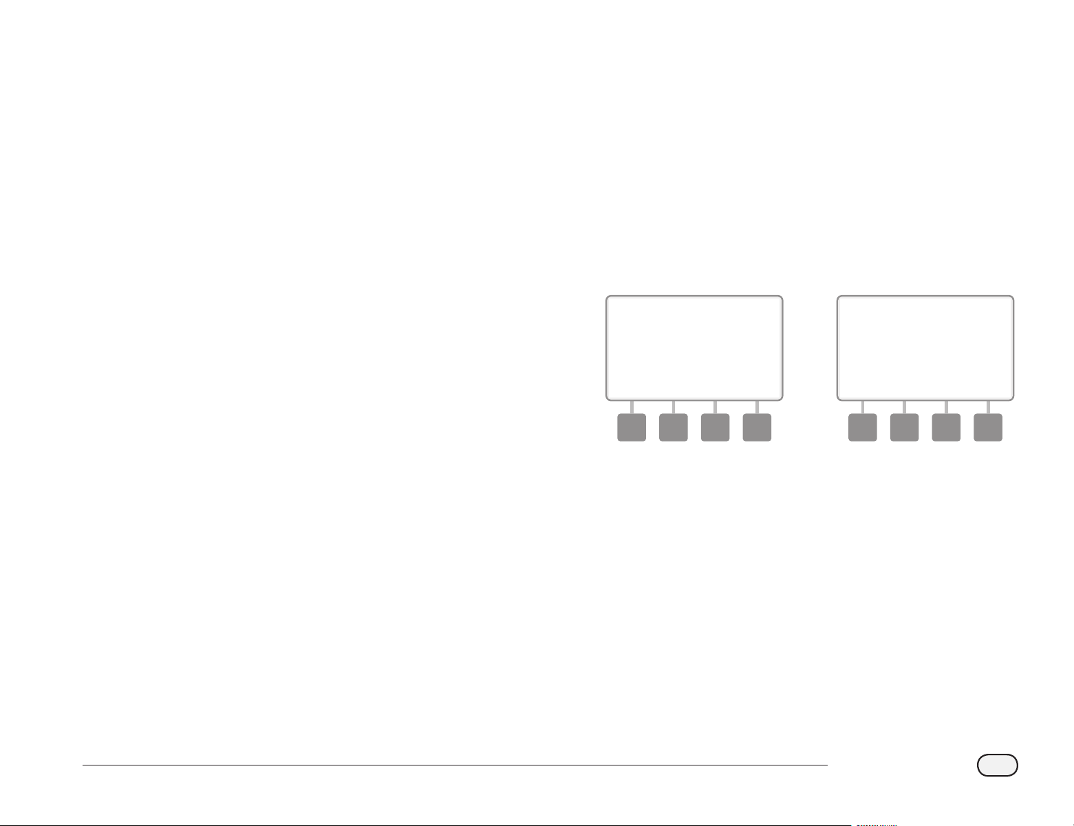
57
ESP-LXD Controller
Set Up Station Delay
The ESP-LXD controller can be programmed to include a delay between
stations. This feature delays the start of the next sequential station in a
program after the previous station completes.
bd
CAUTION: Consider using short Station Delay times, particularly
if your watering schedule or Water Window is short. Long delay
times could prevent scheduled irrigation from completing prior
to the end of the Water Window. See previous Water Windows for
more details.
bg
Turn the controller dial to Station Settings.
A
The Station Settings screen appears. Press the Down Arrow button
to select Station Delay; then press Next.
B
The Delay Between stations screen appears. Press the + and
– buttons to set the delay time (from 00:01 second to 10:00
minutes). Or to clear Station Delay on that station, set to 00:00;
then press Next.
bl
Press and HOLD buttons to accelerate settings for minutes and
seconds.
bb
NOTE: If the desired program is not selected, use the Program
Select switch to change it. See Section B, Program Select Switch
for more details.
1 2
be
Change the Program Select switch and repeat this process to set
Station Delay for other programs as desired.
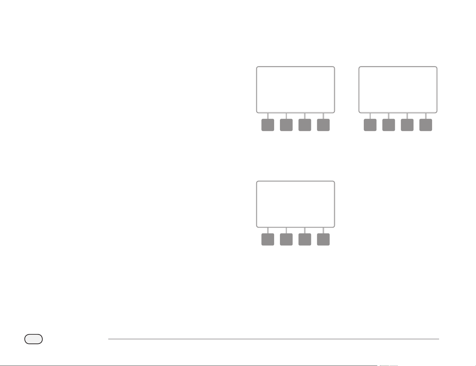
58
ESP-LXD Controller
Set Up SimulStations
TM
To prevent the ESP-LXD controller from irrigating too many stations
simultaneously, you can set the maximum number of stations per
program that are allowed to run. This can be benecial for systems with
a small water source and to help ensure uniform water distribution.
bd
CAUTION: The ESP-LXD can run multiple programs and stations
concurrently. If all four programs are running two stations, then
theoretically 8 stations could be operating at the same time.
Many irrigation systems do not have sucient hydraulic capacity
to accommodate such a load. SimulStations can be used to limit
the maximum number of stations per program or for the entire
controller, but in general we recommend enabling FloManager
and setting program-level and LXD-level SimulStations to a fairly
high number. This will allow FloManager to provide maximum
irrigation based on your system’s hydraulic capacity. Consult the
FloManager portion of this manual in Section F and Appendix C
for additional details.
Set SimulStations
TM
for Program
bg
Turn the controller dial to Station Settings.
A
The Station Settings screen appears. Press the Down Arrow button
to select SimulStations; then press Next.
B
The Station Settings screen appears with PGM SimulStations
selected; press Next.
1 2
C
The Maximum Number of SimulStations screen appears. Press the
+ and – buttons to set the maximum number of irrigation stations
(from 1 to 8) that can operate simultaneously for this program;
then press Next.
3
be
Change the Program Select switch and repeat this process to set
the Maximum Number of Stations for other programs as desired.
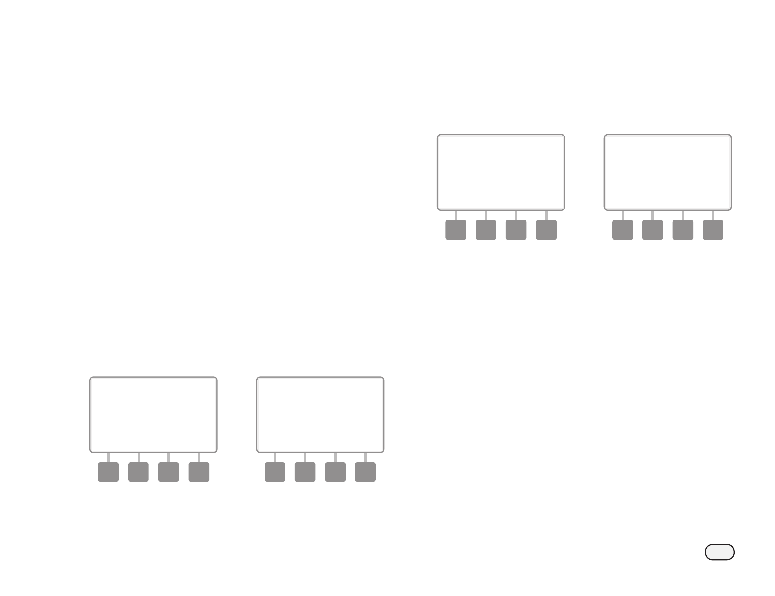
59
ESP-LXD Controller
Set SimulStations
TM
for Controller
bb
NOTE: The LXD SimulStations settings will supersede program-
level settings. For example, if the LXD setting is 2 but three
programs have a maximum setting of 4, then only 2 stations will
be allowed to run simultaneously.
bg
Turn the controller dial to Station Settings.
A
The Station Settings screen appears. Press the Down Arrow button
to select SimulStations; then press Next.
B
The Station Settings screen appears. Press the Down Arrow button
to select LXD SimulStations selected; then press Next.
1 2
C
The ESP-LXD Maximum Number of SimulStations screen appears.
Press the + and – buttons to set the maximum number of irrigation
stations (from 1 to 8) that can operate simultaneously; then press
Next.
D
Press the + and – buttons to set the maximum number of non-
irrigation stations (from 1 to 4).
3 4
bb
NOTE: The Non-Irrigation SimulStations setting is used to
congure the maximum number of Non-Irrigation stations
that can operate simultaneously and allows you to balance the
number of Irrigation and Non-Irrigation stations that can operate
simultaneously. Also note that when SimulStations are set to a
maximum of 8, if a Normally Closed Master Valve has to be held
open for irrigation to occur, it will limit the maximum number of
SimulStations to 7.
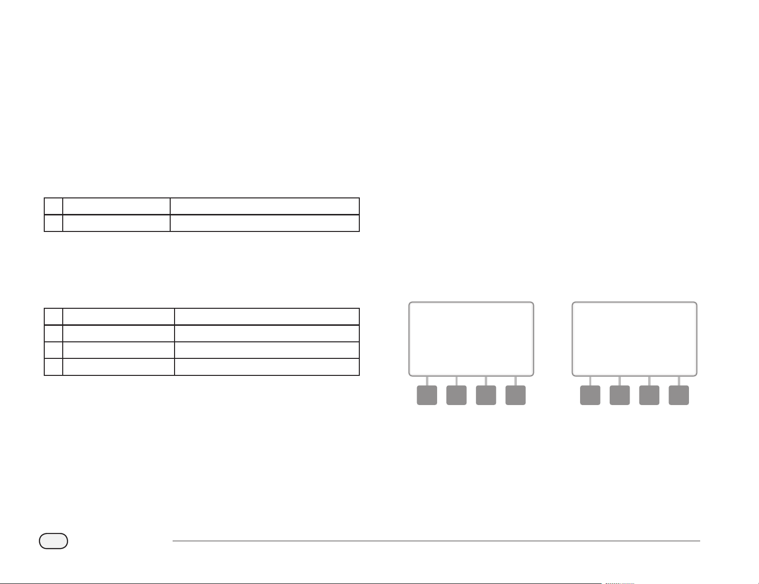
60
ESP-LXD Controller
Station Sequencing
The ESP-LXD oers advanced programming features to optimize water
windows. The Station Sequencing option allows you to select from two
methods of station sequencing for program operation:
bl
Sequence by Station Number (system default).
bl
Sequence by Station Priority (required when using FloManager).
This option decreases the overall time required to complete the
program when operating multiple stations simultaneously.
Station Sequencing by Station Numbers will select stations to
operate in the following order:
1 Station number 1 > 2 > 3 . . .
2 Program assignment A > B > C > D
bb
NOTE: Non-irrigation priority stations will always be selected to
operate rst.
Station Sequencing by Station Priority will select stations to
operate in the following order:
1 Station priority Non-Irrigation > High > Medium > Low
2 Station run time Longest run time > shortest run time
3 Station number 1 > 2 > 3 . . .
4 Program assignment A > B > C > D
bb
NOTE: If FloManager is turned ON, then the default Station
Sequencing setting is Sequence by Station Priorities. To select
Station Sequencing by Station Number, FloManager must rst
be turned OFF. See Section F, Flow Management, Enable/Disable
FloManager for more details.
bg
Turn the controller dial to Station Settings.
A
The Station Settings screen appears. Press the Down Arrow button
to select Station Sequencing; then press Next.
B
The Station Sequencing screen appears. Press the + and – buttons
to set Station Sequencing by either Station Numbers or Station
Priorities, as desired.
1 2
bb
NOTE: When Station Sequencing is set to Sequence by Station
Priorities, you can still manually operate stations in station
number sequence using the Test All Stations option from the
Manual Watering dial position. See Section G, Auxiliary Operation,
Manual Watering, Test All Stations for more details.
61
ESP-LXD Controller
Section E - Options & Special Features
Backup and Recall Programs
The ESP-LXD controller comes standard with a simple to use
backup programs feature.
Backup Programs allows you to save your programs as Contractor
Default and then recall them at a later time. It also includes a Delayed
Recall feature that lets you save a normal irrigation schedule as the
Backup and then restore it later automatically. This may be useful for
new seed or sod where frequent irrigation can be programmed to
occur until a set date when Delayed Recall automatically returns the
controller programming to the normal irrigation schedule.
bd
CAUTION: The Backup Programs feature saves and restores ALL
irrigation programming in ALL programs (A, B, C & D).
bb
NOTE: The ESP-LXD also supports eight program backups using
the optional Programming Backup Cartridge (PBC-LXD). See
Programming Backup Cartridge for more details.
Store Default Programs
bg
Turn the controller dial to Special Features.
A
The Special Features screen appears. Press the Down Arrow
button to select Backup Programs; then press Next.
B
The Backup Programs screen appears with Store Programs
selected; press Next.
1 2
C
A conrmation screen appears. To Store Programs, press and hold
down the Yes button for four seconds. If you’re not sure, press No.
D
A conrmation screen appears.
3 4
62
ESP-LXD Controller
Recall Default Programs
bg
Turn the controller dial to Special Features.
A
The Special Features screen appears. Press the Down Arrow
button to select Backup Programs; then press Next.
B
The Backup Programs screen appears. Press the Down Arrow
button to select Recall Programs; then press Next.
1 2
C
A conrmation screen appears. To Recall Programs, press and hold
down the Yes button for four seconds. If you’re not sure, press No.
D
A conrmation screen appears.
3 4
bd
CAUTION: Once current programs have been replaced using
Recall Programs they can not be restored.
63
ESP-LXD Controller
Delayed Recall
Use the Delayed Recall feature to automatically replace the currently
loaded programs with a previously stored program at a future date.
bd
CAUTION: Once current programs have been replaced with the
Delayed Recall feature, they can not be restored.
bg
Turn the controller dial to Special Features.
A
The Special Features screen appears. Press the Down Arrow
button to select Backup Programs; then press Next.
B
The Backup Programs screen appears. Press the Down Arrow
button to select Delayed Recall; then press Next.
1 2
C
The Recall Delay screen appears. Press the + and – buttons to
enter the number of days (from 0 to 90 days) before Contractor
Defaults are restored. For example, set it to 7 days if you want your
original programs to be restored in one week. If you want to clear
a previously Delayed Recall, set the number of days to 0.
3

64
ESP-LXD Controller
Programming Backup Cartridge (PBC-LXD)
The optional PBC-LXD allows you to manage multiple
Backups of irrigation programming.
An optional Programming Backup Cartridge (PBC-LXD) is available for
the ESP-LXD controller which allows you to create and Restore multiple
Backups of irrigation programs. The PBC-LXD is portable and easy to
install and un-install so you can use a single PBC-LXD with multiple ESP-
LXD controllers.
PBC-LXD Features
A
Reset button - to reset the PBC-LXD.
B
Controller Connectivity - illuminates, blinking when the PBC-LXD
has connectivity to the controller.
C
Barcode Scanning Functionality - illuminates solid when optional
barcode scanning pen is connected.
1
2
3
Programming Backup Cartridge (PBC-LXD)
Barcode Scanning Feature
With a PBC-LXD cartridge installed, you can also set up Field Decoder
addresses using an optional barcode scanning feature.
The PBC-LXD unit ships complete with an accessory PBC-LXD RJ45
Connector Cable for use with a barcode scanning pen. If you do not
plan to use the barcode scanning feature right away then store the
cable away for possible use at a later date.
If you do plan to use a barcode scanning pen then follow the additional
instructions to attach it to the PBC-LXD before closing the cartridge bay
(see Install Barcode Scanning Pen for more details).
PBC-LXD RJ45 Connector Cable
bb
NOTE: It’s not necessary to install the barcode pen feature in
order to use the PBC-LXD Backup and Restore functions.
65
ESP-LXD Controller
Installing a PBC-LXD
The Programming Backup Cartridge (PBC-LXD) gets installed in the
back of the controller front panel.
A
Open the controller outer cabinet door and inner front panel. See
Section H, Access Controller Cabinet for more details.
B
Press down on the top-latch of the cartridge bay cover and
remove it from the back of the controller front panel.
1
2
C
Connect the PBC-LXD ribbon cable to the knife-edge connector
located at the top-left corner inside the cartridge bay of the
controller front panel.
3
D
Orient the cartridge so that the two bottom hinges t into the
hinge openings at the bottom of the cartridge bay. Then gently
swing the PBC-LXD up into place, snapping the top-latch.
4
bg
Turn the controller dial to ETM/IQ/PBC Settings to check that the
controller has recognized the PBC-LXD.
bb
NOTE: There may be a short delay while the ESP-LXD controller
recognizes the newly installed cartridge for the rst time.
bb
NOTE: The PBC-LXD can be operated only in a controller
connected to power. It can not be operated in front panels
powered only by a 9 volt battery.
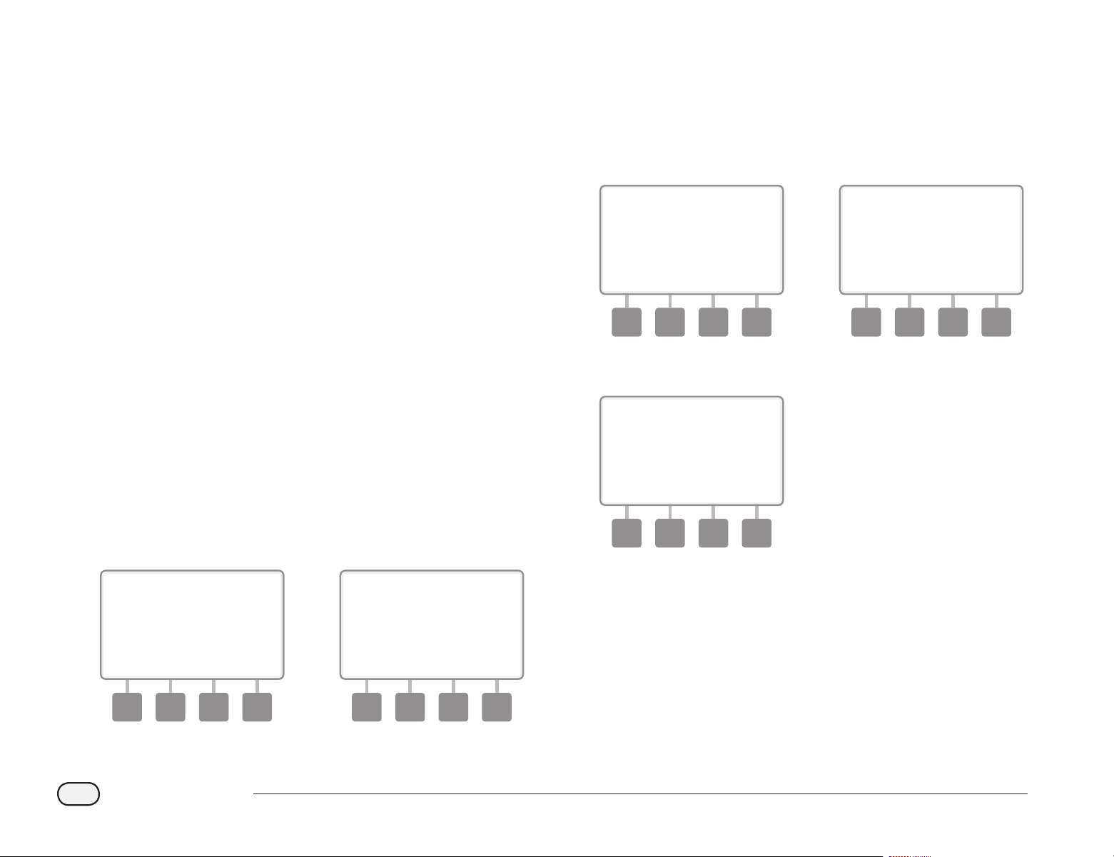
66
ESP-LXD Controller
Backup Programs to PBC-LXD
Follow this procedure to backup irrigation programs.
bg
Turn the controller dial to ETM/IQ/PBC Settings.
A
The PBC Main Menu appears with Backup selected; press Next.
B
The PBC Backup screen appears. Press the + or – buttons to choose
a Backup le; then press Next.
bb
NOTE: 8 dierent Backup les are available, with names that
are assigned automatically (Backup01 through Backup08). The
names cannot be changed but the date and time stamp update
automatically whenever a particular le is used. Unused les
display as <Unused>.
1 2
C
A conrmation screen appears showing the selected Backup le.
Press Next to begin Backup.
bd
CAUTION: If you select a previously used Backup le as the
destination, that le will be overwritten and cannot be recovered.
D
A conrmation screen appears showing that Backup is in progress.
3 4
E
A second conrmation screen appears when Backup is complete.
5
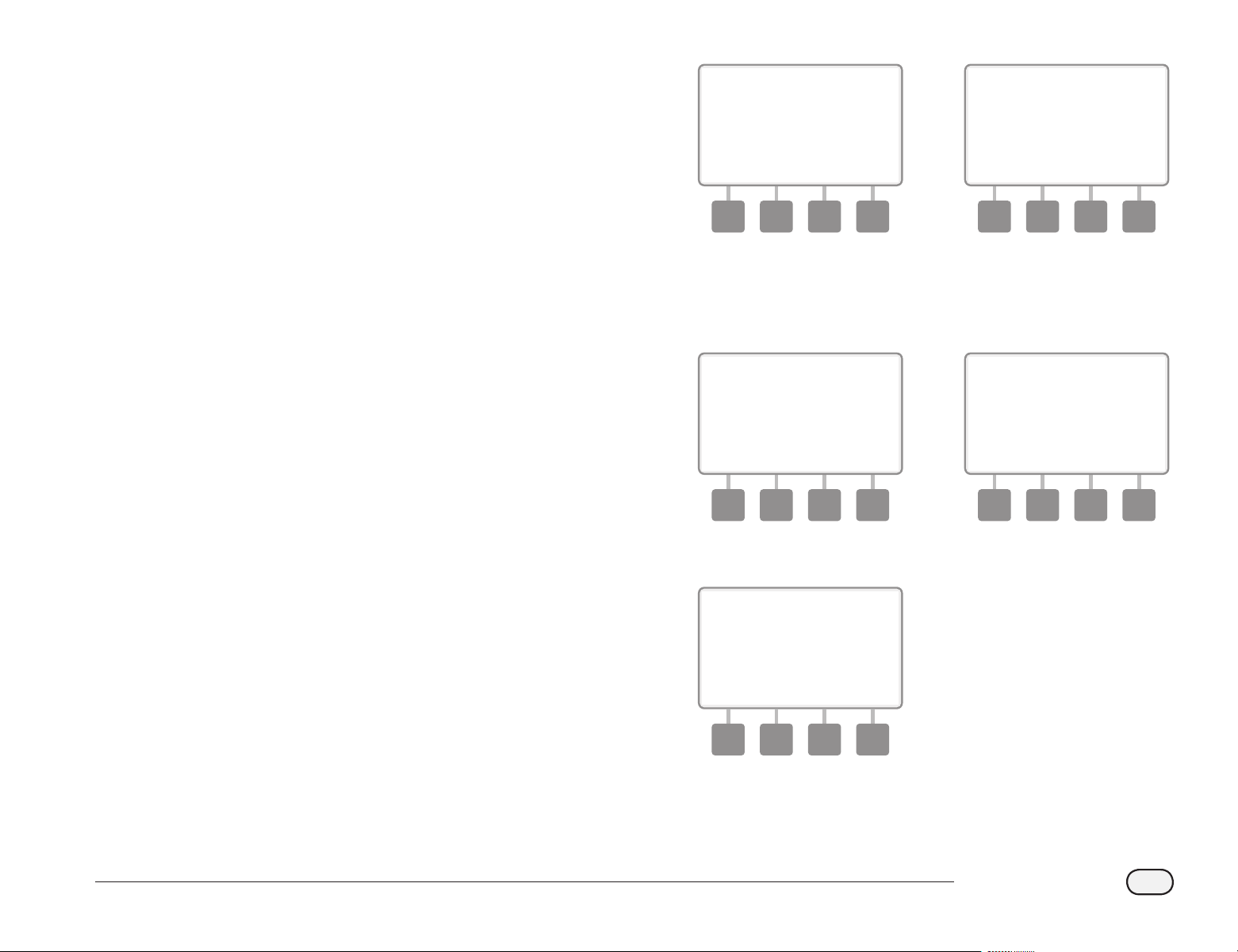
67
ESP-LXD Controller
Restore Programs from PBC-LXD
Follow this procedure to Restore irrigation programs from a previous
Backup.
bd
CAUTION: Restore deletes all current programs and replaces
them with stored programs from the selected Backup le. It’s
recommended to create a temporary Backup of current programs
before using Restore.
bg
Turn the controller dial to ETM/IQ/PBC Settings.
A
The PBC Main Menu appears. Press the Down Arrow button to
select Restore Programs; then press Next.
B
The PBC Restore screen appears. Press the + or – buttons to
choose a Restore le; then press Next.
bb
NOTE: Available les display a creation date and time stamp.
Unused les display as <Unused> and are not available for Restore.
1 2
C
A conrmation screen appears, showing the Backup le selected
for Restore. Press Next to begin Restore.
D
A conrmation screen appears showing that Restore is in progress.
3 4
E
A second conrmation screen appears when Restore is complete.
5
68
ESP-LXD Controller
Decoder Barcode Scanning
The optional Decoder Barcode Scanning feature allows you
to automatically enter Field Decoder Addresses into the ESP-
LXD controller.
Decoder barcode scanning is an optional feature of the Programming
Backup Cartridge (PBC-LXD) that lets you set up Field Decoder addresses
in the ESP-LXD controller by using a barcode scanning pen to read the
removable barcode labels attached to Rain Bird’s eld decoders (see
Programming Guide instructions for more details).
bb
NOTE: The optional barcode scanning pen must be purchased
separately. Rain Bird recommends using a Unitech MS100-2
barcode pen with 9 pin (female) serial connector. Go to www.ute.
com for more details.
Install Barcode Scanning Pen
For this installation, you will need the following:
Programming Backup
Cartridge (PBC-LXD)
Barcode Scanning Pen
(Unitech MS100-2
recommended)
PBC-LXD RJ45
Connector Cable
(Included with PBC-
LXD)
Barcode Scanning Pen Installation Components
A
Open the controller outer cabinet door and inner front panel. See
Section H, Access Controller Cabinet for more details.
B
Press down on the top-latch of the cartridge bay cover (or PBC if
already connected) and remove it from the back of the controller
front panel.
1
2
C
Plug the PBC-LXD RJ45 Connector Cable into the connection jack
on the back-side of the PBC-LXD.
3
69
ESP-LXD Controller
D
Ensure the PBC-LXD ribbon cable is connected to the knife-edge
connector located at the top-left corner inside the cartridge bay
of the controller front panel.
4
E
Orient the PBC-LXD so that the two bottom hinges t into the
hinge openings at the bottom of the cartridge bay. Then gently
swing the PBC-LXD up into place, snapping the top-latch.
5
F
Route the PBC-LXD RJ45 Connector Cable through the cable
channel on the back of the controller front panel.
6
G
Attach the Barcode Scanning Pen cable’s serial connector (9 pin
female) to the PBC-LXD Connector cable’s serial connector (9 pin
male).
7

70
ESP-LXD Controller
Set Up Barcode Scanning Pen
The barcode scanning pen requires initial setup before using.
bb
NOTE: The optional barcode scanning pen must be purchased
separately. Rain Bird recommends using a Unitech MS100-2
barcode pen with 9 pin (female) serial connector. Go to www.ute.
com for more details.
A
Locate the Programming Guide that came with the ESP-LXD
controller.
1
B
On page 26 of the Programming Guide, under Barcode Scanning
Pen Setup, locate Setup Barcode #1. Scan the barcode lengthwise
as shown. You’ll hear audible beep(s) to conrm that the rst scan
was successful.
2
C
Then scan Setup Barcode # 2 and again you’ll hear audible beep(s)
to conrm that the second scan was successful. The barcode
scanning pen is now ready for use.
bb
NOTE: If you do not hear audible beep(s) to conrm scan success
then repeat the process until you hear the beeps.
3

71
ESP-LXD Controller
Test Barcode Scanning Pen
A
Locate the Programming Guide that came with the ESP-LXD
controller.
1
bg
Turn the controller dial to ETM/IQ/PBC Settings.
B
The PBC Main Menu appears. Press the Down Arrow button to
select Test Barcode Pen; then press Next.
C
The PBC Test Barcode Pen screen appears with instructions.
2 3
D
Scan any station Number Barcode (as shown on pages 6-25 of
the Programming Guide). You’ll hear an audible beep to conrm
when the scan was successful.
E
The Success! screen will appear and the station # eld will display
the station number of the scanned barcode.
4 5
bb
NOTE: Return the Programming Guide to a permanent, safe
location when you’re nished working with it. We recommend
hanging it on the hook inside the controller cabinet door.
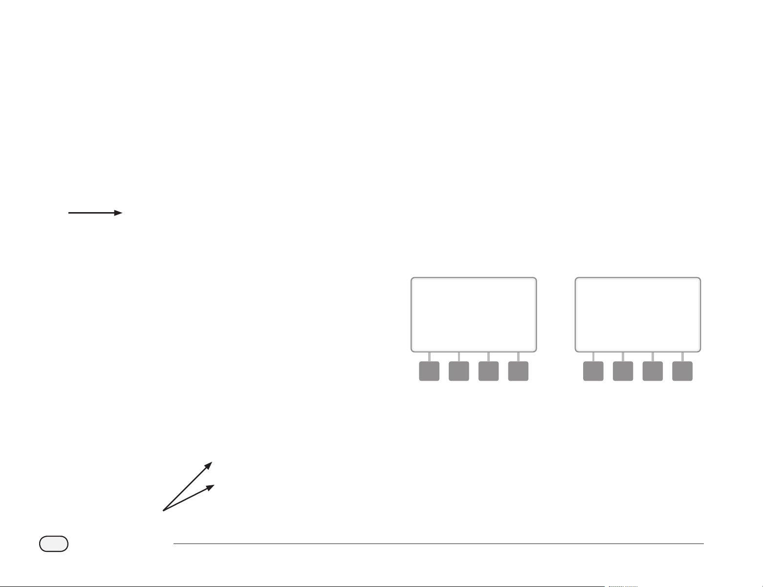
72
ESP-LXD Controller
Scan Field Decoder Addresses
Set up eld decoders automatically by scanning.
bd
CAUTION: Barcode scanning replaces any previous decoder
addresses stored in the controller. Be sure to complete the
previous Test Barcode Scanning Pen process before starting as the
test process will not update or replace your decoder addresses.
A
Locate the Programming Guide that came with the ESP-LXD
controller.
1
B
Ensure that the station Decoder Address Labels are axed in the
proper locations on the Programming Guide (see Programming
Guide instructions for more details).
2
bg
Turn the controller dial to ETM/IQ/PBC Settings.
C
The PBC Main Menu appears. Press the Down Arrow button to
select station Setup; then press Next.
D
The PBC station Setup (Scan When Ready) screen appears.
3 4
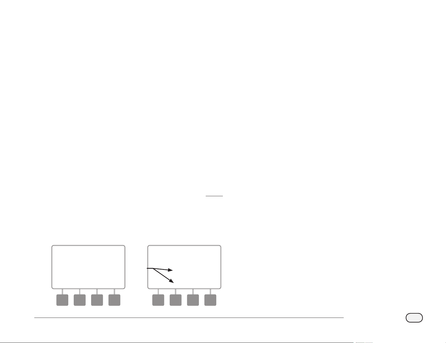
73
ESP-LXD Controller
E
On the Programming Guide, scan a station Number barcode and
corresponding station Decoder Address Label in sequence. You’ll
hear audible beep(s) to conrm when scans are successful.
5
F
The Successful Scan screen appears and the station # and Decoder
# elds will be updated with the scanned barcode data (the screen
will always display the most recently scanned data).
Press the Save button to store the scanned station Number and
station Decoder Address in the controller. Or else press Cancel to
go back or retry scanning again.
bb
NOTE: It’s not necessary to scan Field Decoder addresses
sequentially. Station, Sensor or MV addresses can be scanned in
any numeric order. For example, you could scan station 2 before
scanning station 1, if necessary.
G
To scan master valve, ow sensor or weather sensor decoders;
from the Scan When Ready screen, press the Type button to
select the desired device. Then repeat the scanning process as
previously described.
6 7
bb
NOTE: If either barcode does not scan on the rst attempt, try
scanning one or both barcodes again until you hear the beep(s)
and until the screen has updated to show both the station (or
Sensor or MV) Number and the Decoder Address. If scanning
problems persist, you can still enter decoder addresses manually.
See Section B, Setup Wizards for more details.
be
Repeat this process and continue to scan and set up additional
Field Decoder addresses as desired.
bb
NOTE: Even if you don’t plan to use a barcode scanning pen, we
recommend carefully removing the peel-o barcodes from your
eld decoders and axing them to the proper positions in the
Programming Guide (see the Programming Guide instructions for
more details).
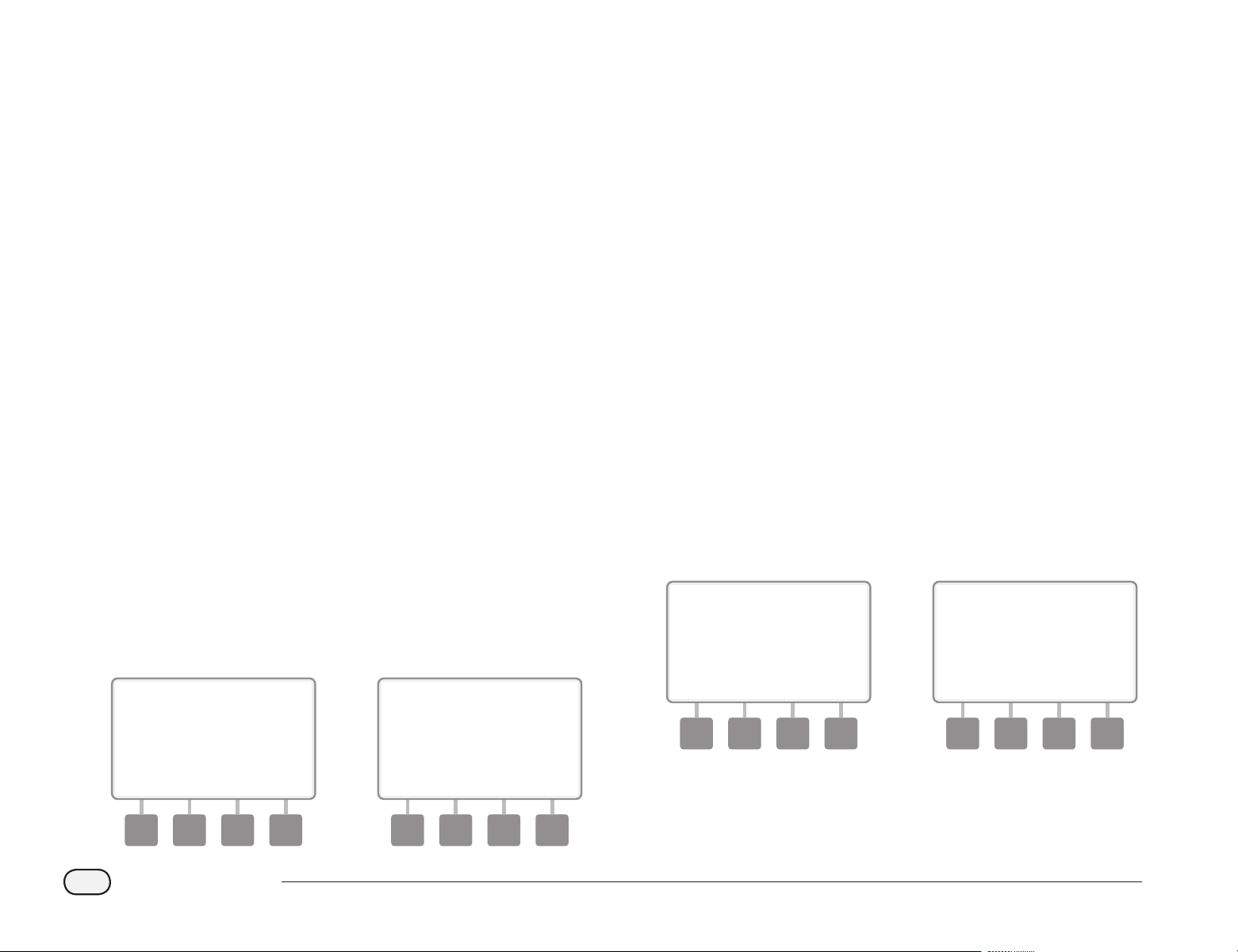
74
ESP-LXD Controller
Special Features
Set Language
You can set the ESP-LXD controller to one of six supported languages;
English, Spanish, French, Portuguese, Italian or German. Changes to the
default language aect all screens and menus.
bg
Turn the controller dial to Special Features.
A
The Special Features screen appears with Set Language selected;
press Next.
bb
NOTE: If the controller is set to a language you do not speak, Set
Language is the top item on the Special Features main menu.
B
The Set Language screen appears. Press the + and – buttons to
select the desired language.
1 2
Set Hours Mode
You can set the ESP-LXD controller to display time in one of three hours
modes; Auto, AM/PM or 24 Hour.
bg
Turn the controller dial to Special Features.
A
The Special Features screen appears with Set Language selected.
Press the Down Arrow button to select Set Hours Mode; then
press Next.
B
The Set Hours Mode screen appears. Press the + and – buttons to
select the desired hours mode.
1 2
bb
NOTE: Auto defaults to AM/PM when 60 Hz power is detected
and to 24 Hour mode when 50 Hz power is detected.
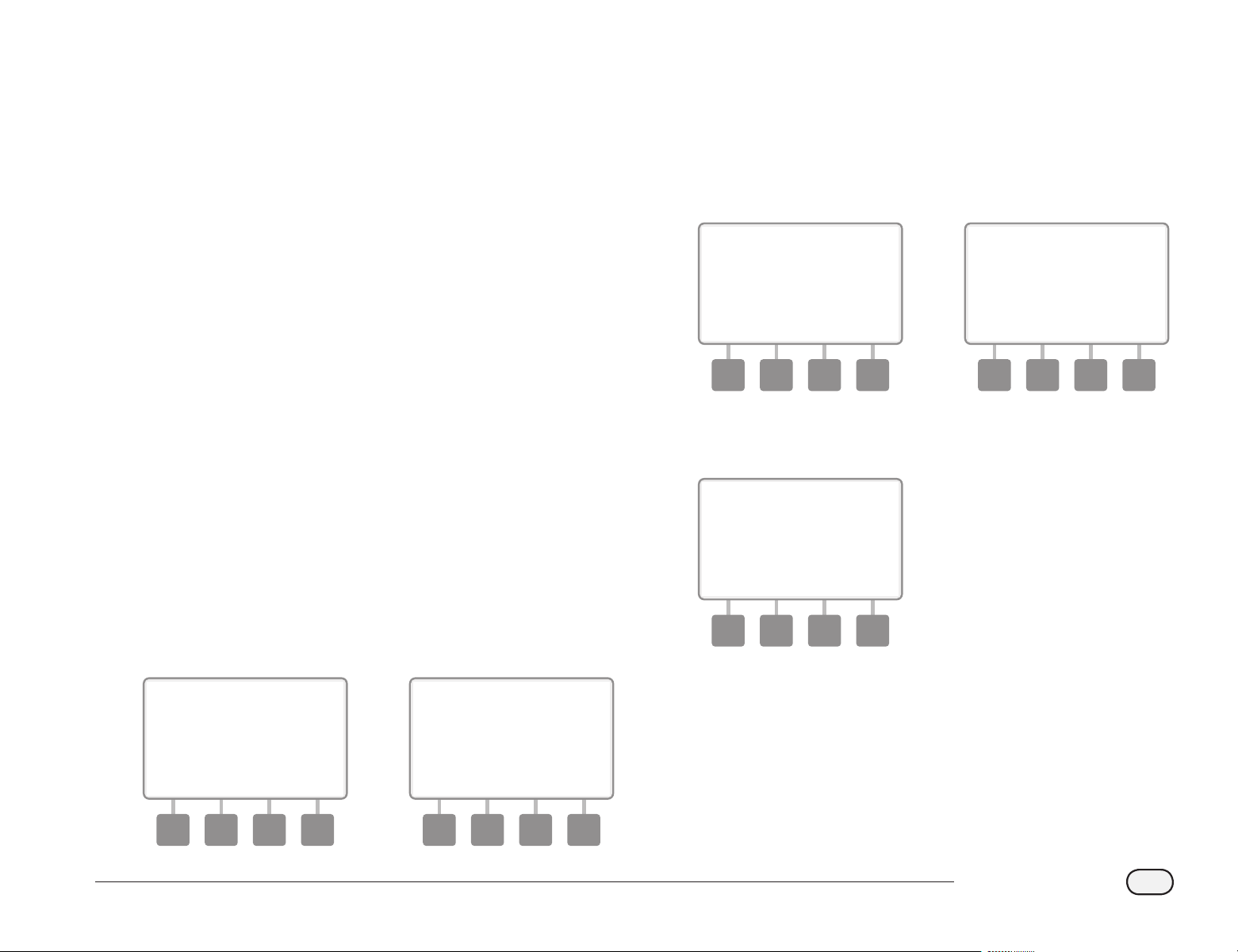
75
ESP-LXD Controller
NOMV Cycling
Since Normally Open Master Valves (NOMVs) are always open, it’s
sometimes helpful to cycle them closed for a minute in order to
maintain the continuity of your valve diaphragms and solenoids. The
controller can be programmed to perform this task automatically.
bb
NOTE: Each NOMV will be cycled closed for 60 seconds on the
rst day of each month. Since irrigation is suspended when the
NOMV is shut, choose a time when irrigation is not scheduled for
this operation.
bg
Turn the controller dial to Special Features.
A
The Special Features screen appears. Press the Down Arrow
button to select NOMV Cycling; then press Next.
B
A conrmation screen appears; press Next when ready.
1 2
C
The NOMV Cycling screen appears. Press the + and – buttons to
set the desired time for cycling to start; then press Next.
bl
Press and HOLD buttons to accelerate settings for hours and
minutes.
D
Press the Yes button to allow cycling to start for each MV or press
No to prevent cycling from starting; then press Next.
3 4
E
Press the Next and Back buttons to navigate through the MVs and
repeat the selection process as desired.
5
bb
NOTE: There is no need to cycle Normally Closed Master Valves
(NCMVs) open, so they are not included in the selection screen.
NCMVs will show as - and can not be changed.
be
Once you advance past the last MV, you will be returned to the
Special Features screen.

76
ESP-LXD Controller
this page intentionally left blank

77
ESP-LXD Controller
Section F - Flow Management
The ESP-LXD controller offers a wide variety of flow-related
functionality to utilize your system more efficiently, with or
without additional flow sensing hardware.
Introduction to Flow
FloZones
TM
Overview
To optimize the controller’s ow features, it’s important to rst
understand FloZones. A FloZone is a collection of one or more stations
all using the same water source. In a simple irrigation system such as a
private residence, water is often supplied from a single source (typically
from the local municipality) and in that case all stations are part of a
single FloZone.
In a typical commercial installation, each FloZone will have it’s water
source(s) controlled by individual Master Valve(s) (or MVs). For this
reason, the number of FloZones is often the same as the number of
MVs. The number of FloZones can never be greater than the number
of water sources and if multiple water sources (and likely MVs) supply
the same section, then the number of FloZones will be less than the
number of MVs.
It’s important to fully understand your system’s hydraulic properties to
set up your water sources, MVs and FloZones appropriately. For more
information on setting up MVs and FloZones. See Section B, Master
Valves Setup for more details.
ESP-LXD Flow Management Features
After understanding and correctly setting up the MVs and FloZones
for your system, the next step is to decide which ow-related features
you’d like to use.
The ESP-LXD controller ow features can be divided into two dierent
functional groups; FloManager and FloWatch.
FloManager
TM
Overview
FloManager adds basic hydraulic management features to your system
to ensure that sucient water pressure and volume is available to
operate all stations. Although it is helpful, ow sensing hardware is not
required to use FloManager. You can manually enter estimated ow
rates even if ow sensing hardware is not installed.
FloWatch
TM
Overview
FloWatch allows you to use any or all of the FloManager features but
adds additional functionality such as alarms for high ow (SEEF) and
low ow (SELF) situations based on parameters you set and control. See
SEEF and SELF Settings and Actions for more details.
bb
NOTE: Flow sensing hardware is required to use FloWatch.
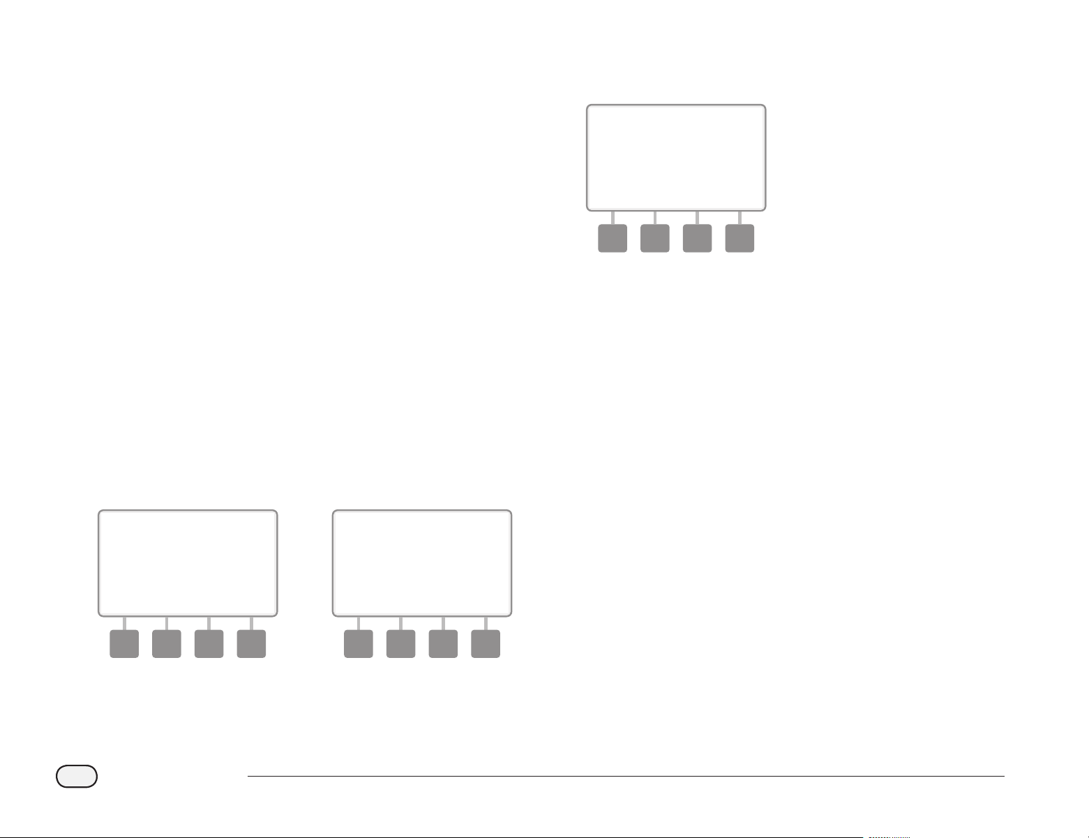
78
ESP-LXD Controller
Set Flow Units
To use FloManager or FloWatch with the ESP-LXD controller, you rst
need to set the measurement units for ow management.
bg
Turn the controller dial to Special Features.
A
The Special Features screen appears. Press the Down Arrow
button to select Set Flow Units; then press Next.
B
The Flow Units screen appears. Press the + and – buttons to select
the desired ow measurement (English or metric); then press
Next.
1 2
C
Press the + and – buttons to select the desired pipe size
measurement (English or metric).
3
bb
NOTE: If Auto is selected, Flow Rate will default to GPM when 60
Hz is detected and to LPS when 50 Hz is detected. Pipe Size will
default to Inches on 60 Hz and to millimeters on 50 Hz.
FloManager
TM
One of the most powerful ow management features in the ESP-LXD
controller is FloManager, which enables the controller to allocate
available water pressure and volume to various stations based on their
hydraulic requirements. This can be done even if ow sensors are not
present.
FloManager works by adding another layer of station or FloZone
prioritization based on available water resources. For example, if
FloZone 1 has 20 GPM available ow and two stations each consuming
6 GPM are currently in operation for a total of 12 GPM, FloManager will
not allow an additional station to start unless it consumes 8 GPM or
less. This helps ensure that your system’s hydraulic resources are not
overtaxed and that sucient water is available to every sprinkler in
every station.
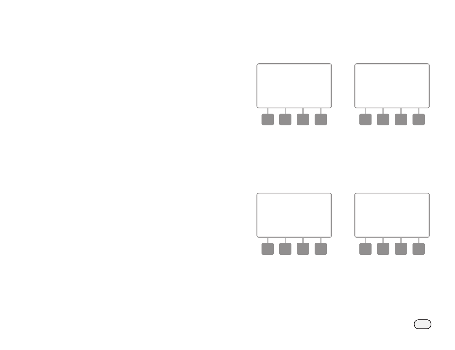
79
ESP-LXD Controller
Set Up and Use FloManager
TM
If you have not already done so, use the Setup Wizards to set up all
master valves and their FloZones. It’s not necessary to install or set
up ow sensors to use FloManager, but if you do have this hardware
present it’s usually helpful to set it up prior to activating FloManager.
See Section B, Flow Sensors Setup for more details.
Once FloManager has been activated we recommend that you Learn
Flow or manually enter ow rates for all stations and FloZones. This will
allow FloManager to dynamically allocate water resources. If you do not
have ow sensing hardware installed you may be able to estimate ow
rates based on the irrigation hardware installed on a particular station
or FloZone and manually enter this rate.
Enable (Or Disable) FloManager
TM
bg
Turn the controller dial to Module Programming.
A
The Smart Module PGM screen appears with Flow Smart Module
selected; press Next.
B
The Flow Smart Module PGM screen appears. Use the Down
Arrow to select FloManager; then press Next.
1 2
C
Press the On button to enable FloManager, or press O to disable.
D
If Station Sequencing was previously set to Station Numbers,
then turning FloManager ON will automatically change the
setting to Station Priorities. Press Accept to make the change or
else press Reject. See Section D, Advanced Programming, Station
Sequencing for more details.
3 4
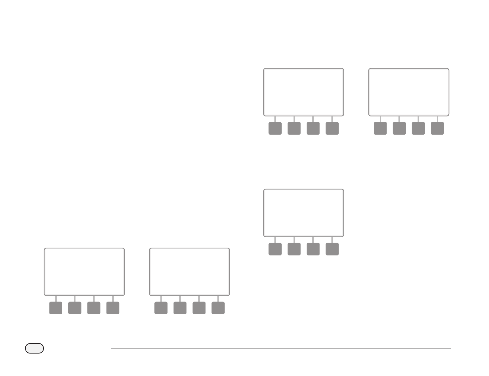
80
ESP-LXD Controller
Set Flow Rates Manually
Allowing the controller to Learn Flow automatically is the easiest, most
accurate method to enter ow readings. However, you can manually
enter ow rates for one or more stations or ow zones before or after
an automatic Learn Flow exercise.
Set Station Rates
bg
Turn the controller dial to Module Programming.
A
The Smart Module PGM screen appears with Flow Smart Module
selected; press Next.
B
The Flow Smart Module PGM screen appears with Set Flow Rates
selected; press Next.
1 2
C
The Set Flow Rates screen appears. Press the Down Arrow button
to select Set Station Rates; then press Next.
D
Press + and – (buttons 1 and 2) to select the desired station
number; then press - (button 4).
3 4
E
Press + and – (buttons 3 and 4) to enter the desired Flow Rate
for that station. Press - (buttons 2 and 4) to navigate between the
station and ow rate elds.
bl
Press and HOLD buttons to accelerate settings for GPM.
5
be
Repeat this process to manually set up Flow Rates for additional
stations as desired.
81
ESP-LXD Controller
Set FloZone
TM
Rates
bg
Turn the controller dial to Module Programming.
A
The Smart Module PGM screen appears with Flow Smart Module
selected; press Next.
B
The Flow Smart Module PGM screen appears with Set Flow Rates
selected; press Next.
1 2
C
The Set Flow Rates screen appears. Press the Down Arrow button
to select Set FloZone Rates; then press Next.
D
The FloZone Flow Rates screen appears. Press + and – (buttons 1
and 2) to select the desired FloZone number; then press - (button
4).
3 4
E
Press + and – (buttons 3 and 4) to enter the desired Flow Rate for
that FloZone. Press – (buttons 2 and 4) to navigate between the
FloZone and Flow Rate elds.
bl
Press and HOLD buttons to accelerate settings for GPM.
bb
NOTE: Maximum FloZone ow rates are used only by FloManager.
FloWatch is unaected by user-entered FloZone ow rates.
5
be
Repeat this process to manually set up Flow Rates for additional
FloZones as desired.
After FloManager is enabled and station and/or FloZone ow rates
are entered, FloManager works automatically in the background to
run stations based on available hydraulic capacity
bb
NOTE: FloManager can be used with or without ow sensing
hardware. If ow sensors are not present it will rely on manually
entered information; if ow sensors are present it will rely on
Learned Flow information, which is typically more accurate.

82
ESP-LXD Controller
FloWatch
TM
FloWatch unleashes the true power of the ESP-LXD controller. FloWatch
compares current ow conditions to expected learned or user-entered
ow rates and takes various actions based on your settings and input.
Since current ow conditions are required, FloWatch can only be used
when ow sensors are present. To use FloWatch, you must do all of the
following:
A. Install ow monitoring hardware into the appropriate locations
of your irrigation system. You should install one ow sensor just
downstream of each master valve but upstream of any valves.
To ensure stable readings, ow sensors should be installed at
least ten times the distance of the pipe diameter downstream of
the Master Valve with an additional ve pipe diameter distance
between the ow sensor and any additional hardware.
B. Connect each ow meter to an SD-210 sensor decoder using
the instructions in the “Connecting Decoders” portion of the
Installation section of this manual.
C. Set up the ow sensors using the ow sensor setup wizard
described in the Setup Wizards portion of the Basic Programming
section of this manual.
D. Follow the directions below to set up FloWatch.
bb
NOTE: Once you have set up ow on your controller, the current
ow rate will be displayed on the Auto screen unless you turn o
FloWatch. For more information on turning FloWatch on and o,
see “Setting Up and Using ow” below.
Set Up and Use FloWatch
TM
The ESP-LXD controller lets you set the ow rates you expect or to
automatically Learn Flow rates based on real usage. Once ow is
learned or manually entered, the SEEF and SELF settings let you dene
the parameters for excessive or low ow and to set the behavior of
the controller when these conditions are detected. You can also turn
FloWatch o or back on again if you like.
FloWatch needs expected ow rates to work properly. Flow rates can
be entered manually or can be learned automatically through a Learn
Flow process. An automatic Learn Flow operation will Learn Flow for
each station that has programmed run times. Ensure you have set
up runtimes for all stations included in a Learn Flow exercise prior to
setting up a Learn Flow.
A FloZone is a group of stations downstream of a master valve and ow
sensor. In a shared main line, stations may be downstream of more than
one master valve and ow sensor. Since LXD supports up to 5 Master
Valves, as many as 5 FloZones can be created. An irrigation system
consisting of 5 MVs owing into 5 individual main lines would result in
5 FloZones. An irrigation system consisting of 5 Master Valves owing
into one shared main line would result in 1 FloZone.
bb
NOTE: Prior to learning or manually setting ow, it is a good idea
to check the master valve assignments for each of your stations.
See the “station Setup” portion of the Setup Wizards portion of
this manual in Basic Programming.
bb
NOTE: Water pressure, particularly from municipal sources, can
vary signicantly throughout the day. To mitigate this variance,
use the time delay option to delay the Learn Flow start time to
when irrigation would normally operate.
83
ESP-LXD Controller
Enable (or Disable) FloWatch
TM
bg
Turn the controller dial to Module Programming.
A
The Smart Module PGM screen appears with Flow Smart Module
selected; press Next.
B
The Flow Smart Module PGM screen appears. Use the Down
Arrow to select FloWatch; then press Next.
1 2
C
The FloWatch screen appears. Use the Down Arrow to select
FloWatch On/O; then press Next.
D
Press the On button to enable FloWatch, or else press O to
disable.
3 4
bb
NOTE: Once FloWatch is enabled we recommend that you
Learn Flow or manually enter ow for all stations and FloZones
if you have not already done so. This will allow FloWatch to react
appropriately to the SEEF and SELF settings.
84
ESP-LXD Controller
SEEF and SELF Settings and Actions
To most eectively use FloWatch, you will want to rst set your SEEF
and SELF thresholds and actions. SEEF stands for Seek and Eliminate
Excessive Flow and deals with how you want your controller to respond
when excessive ow is occurring, as might be the case with a mainline
break or a valve which is stuck in the open position. SELF stands for Seek
and Eliminate Low Flow and deals with what the controller should do
when low ow is present, as might be the case during a pump failure,
municipal water supply issue or when a valve fails to open.
Set Up and Configure SEEF and SELF
bg
Turn the controller dial to Module Programming.
A
The Smart Module PGM screen appears with Flow Smart Module
selected; press Next.
B
The Flow Smart Module PGM screen appears. Use the Down
Arrow to select FloWatch; then press Next.
a b
C
The FloWatch screen appears with SEEF/SELF Settings selected;
press Next.
D
The SEEF Settings screen appears with high ow threshold
selected, allowing you to set the top limit (between 105-200%) of
station ow rate that must be achieved to be considered excessive.
Press the + and – buttons to set the High ow Threshold; then
press Next.
bl
Press and HOLD buttons to accelerate settings for percentages.
bb
NOTE: Consider using the default setting of 130% (or higher) for
SEEF high ow threshold. Using a lower percentage can result in
false alarms due to normal hydraulic variability.
c d
E
Settling Time is selected, allowing you to set the minimum time
(from 1-10 minutes) that a ow rate must remain at (or above) the
threshold before the controller will issue an alarm or take action.
Press the + and – buttons to set the Settling Time; then press Next.
85
ESP-LXD Controller
F
The SEEF Actions screen appears, allowing you to set the
controller’s behavior when a SEEF condition exists.
A. Diagnose and Eliminate allows the controller to determine if
the high ow condition is due to a problem on the mainline
(broken pipe, stuck valve, etc) or downstream of one of the valves
that was running when the high ow condition was detected.
The controller will eliminate the high ow condition by closing
the FloZone master valve(s) to eliminate a mainline problem or
closing the problem valve to eliminate a problem with a station.
bb
NOTE: If you choose the Diagnose and Eliminate action, be aware
that all FloZones, stations and hardware, including FloZones
unaected by a SEEF or SELF and non-irrigation hardware, may be
temporarily shut down during the SEEF or SELF diagnostic process.
For this reason, if uninterrupted operation of non-irrigation
hardware, even during a SEEF or SELF diagnostic procedure,
is critical for your installation we recommend operating non-
irrigation hardware with latching relays or selecting a SEEF and
SELF Action other than Diagnose and Eliminate.
B. Shut Down and Alarm instructs the controller to shut down
the master valve(s) on the FloZone when a high ow condition
is detected. The controller will not attempt to diagnose if the
problem is on the mainline or downstream of a valve.
C. Alarm Only allows the controller to issue an alarm condition, but
take no other action.
Press the + and – buttons to set the SEEF Action; then press Next.
e f
G
The SELF Settings screen appears with low ow threshold
selected, allowing you to set the bottom limit (between 1-95%)
that a station must achieve to be considered low ow. Press the +
and – buttons to set the low ow threshold; then press Next.
bl
Press and HOLD buttons to accelerate settings for percentages.
bb
NOTE: Consider using the default setting of 70% (or lower) for
SEEF low ow threshold. Using a higher percentage can result in
false alarms due to normal hydraulic variability.
H
Settling Time is selected, allowing you to set the time limit (from
1-10 minutes) that a station ow rate must remain at (or below)
the threshold before the controller will issue an alarm or take
action. Press the + and – buttons to set the Settling Time; then
press Next.
g h
bb
NOTE: If you are using Cycle+Soak, be sure to set your SEEF
and SELF settling times shorter than the cycle portion of your
Cycle+Soak station runtimes. A SEEF or SELF condition can not be
detected if the SEEF and SELF settling times are equal to or longer
than station cycle times.
86
ESP-LXD Controller
I
The SELF Actions screen appears, allowing you to set the
controller’s behavior when a SELF condition exists.
A. Diagnose and Eliminate allows the controller to determine if the
low ow condition is due to a problem on the mainline (aects
all valves in FloZone) or downstream of one of the valves that
was running when the low ow condition was detected. The
controller will eliminate the low ow condition by closing the
FloZone master valve(s) to eliminate a mainline problem or
closing the problem valve to eliminate a problem with a station.
B. Shut Down and Alarm instructs the controller to shut down
the master valve(s) on the FloZone when a low ow condition
is detected. The controller will not attempt to diagnose if the
problem is on the mainline or downstream of a valve.
C. Alarm Only allows the controller to issue an alarm condition, but
take no other action.
Press the + and – buttons to set the SELF Action; then press Next.
J
The Delay to Re-Enable screen appears, allowing you to select
how long (from 0 to 24 hours) before your system is re-enabled
and program starts are allowed.
bb
NOTE: If you select a Delay to Re-Enable time of 00:00, the
controller will not attempt to start irrigation again until you have
cleared all SEEF and SELF alarms.
Press the + and – buttons to set hours before Re-Enable; then
press Next.
bl
Press and HOLD buttons to accelerate settings for hours and
minutes.
bb
NOTE: If the selected action for both SEEF and SELF is Alarm
Only, then the system is not disabled and the Delay to Re-Enable
screen will not be shown.
i j
K
Press the + and – buttons to set minutes before Re-Enable; then
press Next.
k
bb
NOTE: SEEF and SELF settings are not active until FloWatch is
activated. You may also wish to temporarily disable FloWatch
occasionally, such as when normal maintenance is occurring.
87
ESP-LXD Controller
Learn Flow
FloZone ow rates are either:
a. Automatically set to the highest station ow rate assigned to
the FloZone, or
b. Manually adjusted by the user.
Learn Flow Automatically (All Stations)
bg
Turn the controller dial to Module Programming.
A
The Smart Module PGM screen appears with Flow Smart Module
selected; press Next.
B
The Flow Smart Module PGM screen appears with Set Flow Rates
selected; press Next.
1 2
C
The Set Flow Rates screen appears with Learn Flow selected; press
Next.
D
The Learn Flow screen appears with All stations selected; press
Next.
3 4
bb
NOTE: Ensure you have runtimes set up for all stations included
in a Learn Flow exercise prior to setting up a Learn Flow.
E
Press the + and – buttons to set the time when you want the Learn
Flow exercise to start; then press Next.
bl
Press and HOLD buttons to accelerate settings for hours and
minutes.
bb
NOTE: You can choose to run the exercise Now or choose a timed
delay of up to 24 hours.
F
A conrmation screen appears; press Next again to set the Learn
Flow exercise.
5 6
88
ESP-LXD Controller
G
The Learn Flow Starting conrmation screen appears, conrming
the delay time until the Learn Flow operation will start.
7
bb
NOTE: To ensure accurate recording of ow rates, do not create
any manually-generated ow such as ow created with manually
operated quick coupling valves, while a Learn Flow is taking place.
bb
NOTE: Be sure to Learn Flow again if you make any changes to
your system which aect its hydraulics.
bb
NOTE: If the ow rates for one or more stations seem low, check
your ow metering hardware and ow sensor. Low ow readings
can be caused by faulty ow meters or ow sensors.
Learn Flow Automatically (Custom Stations)
bg
Turn the controller dial to Module Programming.
A
The Smart Module PGM screen appears with Flow Smart Module
selected; press Next.
B
The Flow Smart Module PGM screen appears with Set Flow Rates
selected; press Next.
1 2
89
ESP-LXD Controller
C
The Set Flow Rates screen appears with Learn Flow selected; press
Next.
bb
NOTE: Ensure you have runtimes set up for all stations included
in a Learn Flow exercise prior to setting up a Learn Flow. If stations
without run times are included in a Learn Flow exercise, the
controller will issue an error message and cancel the Learn Flow
exercise.
D
The Learn Flow screen appears. Press the Down Arrow to choose
Select stations; then press Next.
3 4
E
Press the Yes and No buttons to select the stations you would like
to include. Press Next and Back buttons to select stations; then
press Next.
F
Press the + and – buttons to set the timed delay when you want
the Learn Flow exercise to start; then press Start.
bl
Press and HOLD buttons to accelerate settings for hours and
minutes.
bb
NOTE: You can choose a delay between 0 hours, 0 minutes up to
24 hours.
5 6
G
A conrmation screen appears; press Start again to set the Learn
Flow exercise.
H
The Learn Flow Starting conrmation screen appears, conrming
the delay time until the Learn Flow operation will start.
7 8
bb
NOTE: Station or FloZone ow rates can still be entered manually.
See Set Flow Rates Manually in the FloWatch section.
90
ESP-LXD Controller
View and Clear Flow Alarms
Occasionally a ow condition in excess of your SEEF settings or below
your SELF settings will be detected. If your controller is set up to issue
alarms for these conditions, the alarm light will illuminate and detailed
descriptions of the Flow Alarm conditions will be created.
View Station Flow Alarms
bg
Turn the controller dial to Module Status.
A
The Smart Module Status screen appears with Flow Smart Module
selected; press Next.
B
The Flow Module Status screen appears with View Flow Alarms
selected; press Next.
1 2
C
The Review/Clear Alarms screen appears with station Flow Alarms
selected; press Next.
D
The station Flow Alarms screen appears. Press the + and – buttons
to view other station ow alarms.
3 4
Note each station which has an alarm, then see Clear Flow Alarms in
this section for more details on how to clear ow alarms.
91
ESP-LXD Controller
View FloZone
TM
Flow Alarms
bg
Turn the controller dial to Module Status.
A
The Smart Module Status screen appears with Flow Smart Module
selected; press Next.
B
The Flow Module Status screen appears with View Flow Alarms
selected; press Next.
1 2
C
The Review/Clear Alarms screen appears. Press the Down Arrow
button to select FloZone Flow Alarms; then press Next.
D
The FloZone Flow Alarms screen appears. Press the + and –
buttons to view other FloZone ow alarms.
3 4
Note each station which has an alarm, then See Clear Flow Alarms in
this section for more details on how to clear ow alarms.
92
ESP-LXD Controller
Clear Flow Alarms
bg
Turn the controller dial to Module Status.
A
The Smart Module Status screen appears with Flow Smart Module
selected; press Next.
B
The Flow Module Status screen appears with View Flow Alarms
selected; press Next.
1 2
C
The Review/Clear Alarms screen appears. Press the + and – button
to select Clear Flow Alarms; then press Next.
D
The Clear Flow Alarms screen appears. Press Yes to clear all station
and FloZone ow alarms.
3 4
93
ESP-LXD Controller
View Flow Rates
Occasionally you may want to view ow rates and their source for a
station or ow zone.
View Flow Rates for Stations
bg
Turn the controller dial to Module Status.
A
The Smart Module Status screen appears with Flow Smart Module
selected; press Next.
B
The Flow Module Status screen appears. Press the Down Arrow
button to select View Flow Rates; then press Next.
1 2
C
The Flow Rates screen appears with View station Rates selected;
press Next.
D
The station Flow Rates screen appears. Press the + and – buttons
to select the desired station number. The ow zone for each
station displays below it. The normal ow rate for each station will
display to the right, and the source of the ow rate (Learned or
User Entered) displays below it.
3 4
94
ESP-LXD Controller
View Flow Rates for FloZones
TM
bg
Turn the controller dial to Module Status.
A
The Smart Module Status screen appears with Flow Smart Module
selected; press Next.
B
The Flow Module Status screen appears. Press the Down Arrow
button to select View Flow Rates; then press Next.
1 2
C
The Flow Rates screen appears. Press the Down Arrow button to
select View FloZone Rates; then press Next.
D
The FloZone Flow Rates screen appears. Press the + and – buttons
to select the desired FloZone number. The MVs and sensors
associated with that ow zone display below it. The maximum
ow rate for that ow zone will display to the right.
3 4
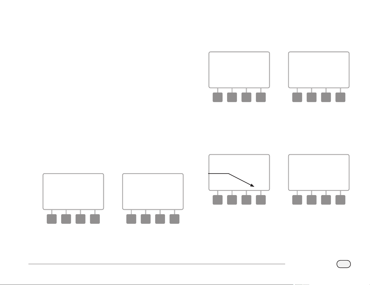
95
ESP-LXD Controller
View and Clear Flow Logs
With FloWatch enabled, the controller will automatically track the
volume of water owing through the system. This can be useful for
checking your actual water consumption against your water bill.
bg
Turn the controller dial to Module Status.
A
The Smart Module Status screen appears with Flow Smart Module
selected; press Next.
B
The Flow Module Status screen appears. Press the Down Arrow
button to select View ow Logs; then press Next.
1 2
C
The Flow Logs screen appears, showing month-to-date and last
month water consumption (in gallons).
D
Press the Days button to change the view to the last 30 days and
previous 30 days.
3 4
E
If you would like to clear the log information, press the Clear
button.
bb
NOTE: Pressing Clear from either the monthly or daily screen will
clear BOTH monthly and daily ow log data.
F
The conrmation screen appears; press Yes to clear the logs.
5 6
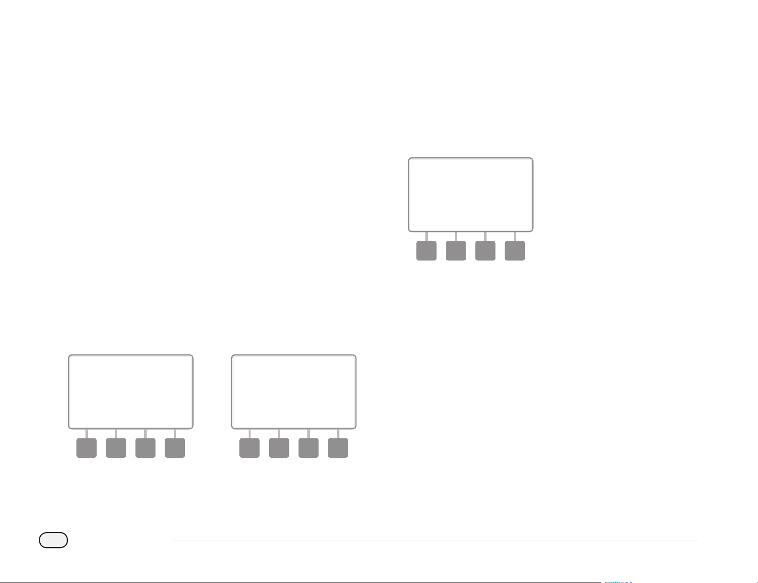
96
ESP-LXD Controller
View Current Flow
Occasionally it may be useful to check the current ow rate in a
particular FloZone and how that compares to previously learned or
user input ow rates.
bg
Turn the controller dial to Module Status.
A
The Smart Module Status screen appears with Flow Smart Module
selected; press Next.
B
The Flow Module Status screen appears. Press the Down Arrow
button to select View Current ow; then press Next.
1 2
C
The View Current Flow screen appears. Press the + and – buttons
to select the desired FloZone number. Current and expected ow
will display.
bb
NOTE: Expected ow is from previously user-entered or learned
ow. The deviation or percentage comparison of current ow to
expected ow will display so you can see how close each FloZone
is to a SEEF or SELF condition (see Setting Up SEEF and SELF for
more details).
3
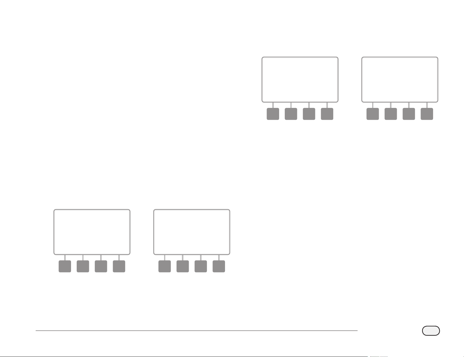
97
ESP-LXD Controller
Clear Flow Rates
Occasionally it may be desired to clear the previously learned or user
entered ow rates and start all over again.
bg
Turn the controller dial to Module Programming.
A
The Smart Module PGM screen appears with Flow Smart Module
selected; press Next.
B
The Flow Smart Module PGM screen appears with Set Flow Rates
selected; press Next.
1 2
C
The Set Flow Rates screen appears. Press the Down Arrow button
to select Clear Flow Rates; then press Next.
D
The conrmation screen appears; press Next to clear ow rates.
3 4

98
ESP-LXD Controller
this page intentionally left blank
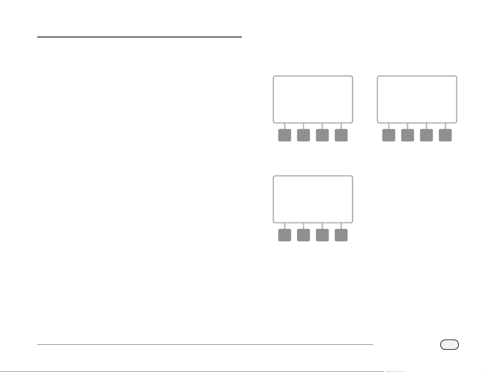
99
ESP-LXD Controller
A
The Smart Module Status screen appears. Use the Down Arrow to
select Station Module(s); then press Next.
B
The LXD Station Modules screen appears showing all recognized
modules. Press Back to return to the previous screen or press Next
to review ow and Weather Sensors.
1 2
C
Pressing Next displays the number of supported ow and weather
sensors.
3
bb
NOTE: If the controller does not recognize an installed module,
carefully remove it and review the installation instructions in
Section H of this manual. Then re-install the module and repeat
this process.
Section G - Auxiliary Operation
Module Status
Confirm that your ESP-LXD controller recognizes installed
Station Modules.
The standard ESP-LXD-M50 module will use two of the four available
slots. You can also expand station capacity by 75-150 stations by
installing one or two ESP-LXD-SM75 Station Modules.
Smart Module Status
Check Station Module(s)
bg
Turn the controller dial to Module Status.
100
ESP-LXD Controller
Clear Programs
The ESP-LXD controller allows you to clear an individual
Program, all of your Programs or Restore the controller to it’s
factory default condition.
bd
CAUTION: It’s recommended to back up your Programs before
clearing them. The ESP-LXD controller’s built in Store Programs
feature can backup one set of programs. See Section E, Backup
and Recall for more details.
bb
NOTE: Irrigation start days, Start Times and station Run Times will
no longer be present for the cleared Programs. If no Programming
exists then an Alarm will be displayed. See Section A, Alarm
Conditions for more details.
Clear Individual Program
bg
Turn the controller dial to Clear Programs.
A
The Clear Programs screen appears with Individual Program
selected; press Next.
B
A conrmation screen appears. To clear the selected Program,
press and hold down the Yes button for four seconds. If you’re not
sure, press No.
bb
NOTE: If the desired Program is not selected, use the Program
Select switch to change it. See Program Selection in Section A for
more details.
1 2
C
A conrmation screen appears.
3
be
Change the Program Select switch and repeat this process to clear
other Programs.
101
ESP-LXD Controller
Clear All Programs
bg
Turn the controller dial to Clear Programs.
A
The Clear Programs screen appears. Press the Down Arrow button
to select All Programs; then press Next.
B
A conrmation screen appears. To Clear All Programs, press and
hold down the Yes button for four seconds. If you’re not sure,
press No.
1 2
C
A conrmation screen appears.
3
102
ESP-LXD Controller
Restore Defaults
Restore the ESP-LXD controller’s factory default settings.
bg
Turn the controller dial to Clear Programs.
A
The Clear Programs screen appears. Press the Down Arrow button
to select Restore Defaults; then press Next.
B
A conrmation screen appears. To Restore Factory Defaults, press
and hold down the Yes button for four seconds. If you’re not sure,
press No.
1 2
C
A conrmation screen appears.
3
bd
CAUTION: Be very careful about using the Restore Defaults
option as all previous settings, including decoder addresses, will
be permanently cleared from system memory. Consider using the
Clear All Programs option instead so that your decoder addresses
will not be erased.
103
ESP-LXD Controller
Manual Watering
The ESP-LXD controller allows you to manually start a station, a
program, or to open a Normally Closed Master Valve (NCMV) to provide
water to a FloZone for manual watering.
Start Station Manually
bb
NOTE: Manual Watering > Start Station will pause currently
running programs.
bb
NOTE: Ensure decoder addresses are present and entered
correctly prior to Manual Station or Manual Program operations.
bg
Turn the controller dial to Manual Watering.
A
The Manual Watering screen appears with Start Station selected;
press Next.
B
The Manual Watering screen appears. Press the + and – buttons
to enter the station you want to run manually; then press Next.
bl
Press and HOLD buttons to accelerate settings for hours and
minutes.
1 2
C
The Station Run Time will default to the Program Run Time. Press
the + and – buttons to adjust the station Run Time (from 0 hours,
1 minute to 12:00 hours). Press the Run button to start irrigation
for that station.
D
A conrmation screen appears.
3 4
be
Repeat this process to manually water other stations.
bb
NOTE: stations will run sequentially in the order in which they
were selected.
bb
NOTE: To view the Station while running, turn the controller dial
to AUTO position. You can use the Adv button to advance to the
next station and the + and – buttons to increase or decrease the
Run Time of the current station.
104
ESP-LXD Controller
Start Program Manually
bg
Turn the controller dial to Manual Watering.
A
The Manual Watering screen appears. Press the Down Arrow
button to select Start Program; then press Next.
B
The Manual Watering Start Program screen appears. Press Run to
start the Program or else press Back to cancel.
bb
NOTE: If the desired Program is not selected, use the Program
Select switch to change it. See Program Selection in Section A for
more details.
1 2
C
A conrmation screen appears.
3
be
Repeat this process to manually start other Programs. Programs
will run sequentially in the order in which they were selected.
bb
NOTE: To view the Program while running, turn the controller
dial to AUTO position. You can use the Adv button to advance to
the next station and the + and – buttons to increase or decrease
the Run Time of the current station.
105
ESP-LXD Controller
MV Water Window
Sometimes you may want to use quick coupling valves or other manual
watering methods during times when you are not irrigating. To ensure
that these devices have water, you can set up an MV Water Window. The
MV Water Window works the same way as other Water Windows, but
instead of allowing irrigation it simply opens Normally Closed master
valves (NCMVs) and allows a user-dened ow rate to coordinate with
ow sensing.
Set Up MV Water Window
bg
Turn the controller dial to Manual Watering.
A
The Manual Watering screen appears. Press the Down Arrow
button to select MV Water Window ; then press Next.
B
The MV Water Window screen appears with MV Water Window
selected; press Next.
1 2
C
Press the + and – buttons to set the time when the MV Water
Window opens; then press Next.
bl
Press and HOLD buttons to accelerate settings for hours and
minutes.
D
Press the + and – buttons to set the time when the MV Water
Window closes. As you adjust the end time, the duration of your
MV Water Window calculates automatically; then press Next.
bb
NOTE: To clear a previously set MV Water Window, press the + and
– buttons to set both the Open and Close times to OFF (between
11:59 and 12:00 AM).
3 4
106
ESP-LXD Controller
E
The MV Manual Watering Allowed On screen appears. Press the
Yes button to allow MV Manual Watering to occur on a given day
or press No to exclude that day.
F
Press the Next and Back buttons to navigate through the days of
the week and repeat the selection process as desired; then press
Next to navigate past Sunday.
5 6
G
The MVs included in Water Window screen appears allowing you
to choose which MVs to include in the MV Water Window. Press
the Yes button to include the selected MV in the Water Window or
press No to exclude it.
H
Press the Next and Back buttons to navigate through the days of
the week and repeat the selection process as desired.
7 8
I
If FloWatch is enabled, the controller will request incremental ow
allowed for the MV Water Window. Press the + and – buttons to
enter a suciently large value so that ow from hoses and other
manual watering devices will not trigger a false SEEF alarm.
i
107
ESP-LXD Controller
Manually Opening a MV
Occasionally it may be necessary to provide water to the system
for unscheduled tasks. The Open MV feature allows you to leverage
settings, such as allowable incremental ow, from your MV Water
Window to open MVs for a short time.
bg
Turn the controller dial to Manual Watering.
A
The Manual Watering screen appears. Press the Down Arrow
button to select MV Water Window ; then press Next.
B
The MV Water Window screen appears. Press the Down Arrow
button to select Manual MV Open ; then press Next.
1 2
C
The Manual MV Open screen appears, showing all MVs that were
previously selected to be included in the MV Water Window; press
Next
D
The Manual MV Open screen appears. Press the + and – buttons
to set the duration (in hours and minutes) for the MV to be open;
then press Start.
bl
Press and HOLD buttons to accelerate settings for hours and
minutes.
3 4
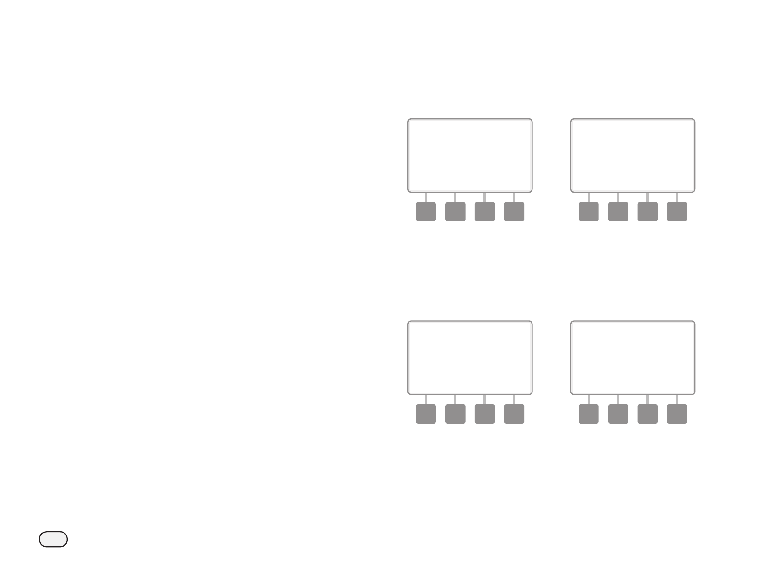
108
ESP-LXD Controller
Test All Stations
You can test all stations connected to your controller by running each
of them in station number sequence.
Sometimes this is useful after installation, for general maintenance or
as a rst step in troubleshooting your system.
bb
NOTE: Only stations with programmed run times are included in
the Test All Stations operation.
bg
Turn the controller dial to Manual Watering.
A
The Manual Watering screen appears. Press the Down Arrow
button to select Test All stations; then press Next.
B
The Test All stations screen appears. Press the + and – buttons to
adjust the Test Run Time (adjustable from 1 to 10 minutes) per
station; then press Run.
1 2
C
A conrmation screen appears.
D
Once Run is pressed, stations can be monitored and advanced by
turning the dial to the AUTO position and using the Adv button.
Press the + and – buttons to increase or decrease Run Time
minutes for the current station.
3 4

109
ESP-LXD Controller
this page intentionally left blank

110
ESP-LXD Controller
OFF
Turn off irrigation, master valves or the 2-Wire path.
Adjust Display Contrast
Adjust the contrast settings for the controller display for better
visibility.
bg
Turn the controller dial to OFF.
A
The All Watering O screen appears and the current contrast
adjustment setting will display for 10 seconds. Press the + and –
buttons to adjust contrast up or down.
1
Turn Off 2-Wire Path
Sometimes you may want to turn o the 2-Wire path, such as when
you’re maintaining your system. The ESP-LXD controller lets you do this
automatically so you do not need to un-wire the 2-Wire path from the
connection lugs.
bd
CAUTION: Always turn o 2-Wire path before maintaining
hardware connected to the 2-Wire path. The 2-Wire path is always
powered even when irrigation is not scheduled.
bb
NOTE: Irrigation functions, including: ow sensors, weather
sensors and eld decoders will be non-operational when the
2-Wire path is powered down.
Power Down or Restore Power to the 2-Wire Path
bg
Turn the controller dial to OFF
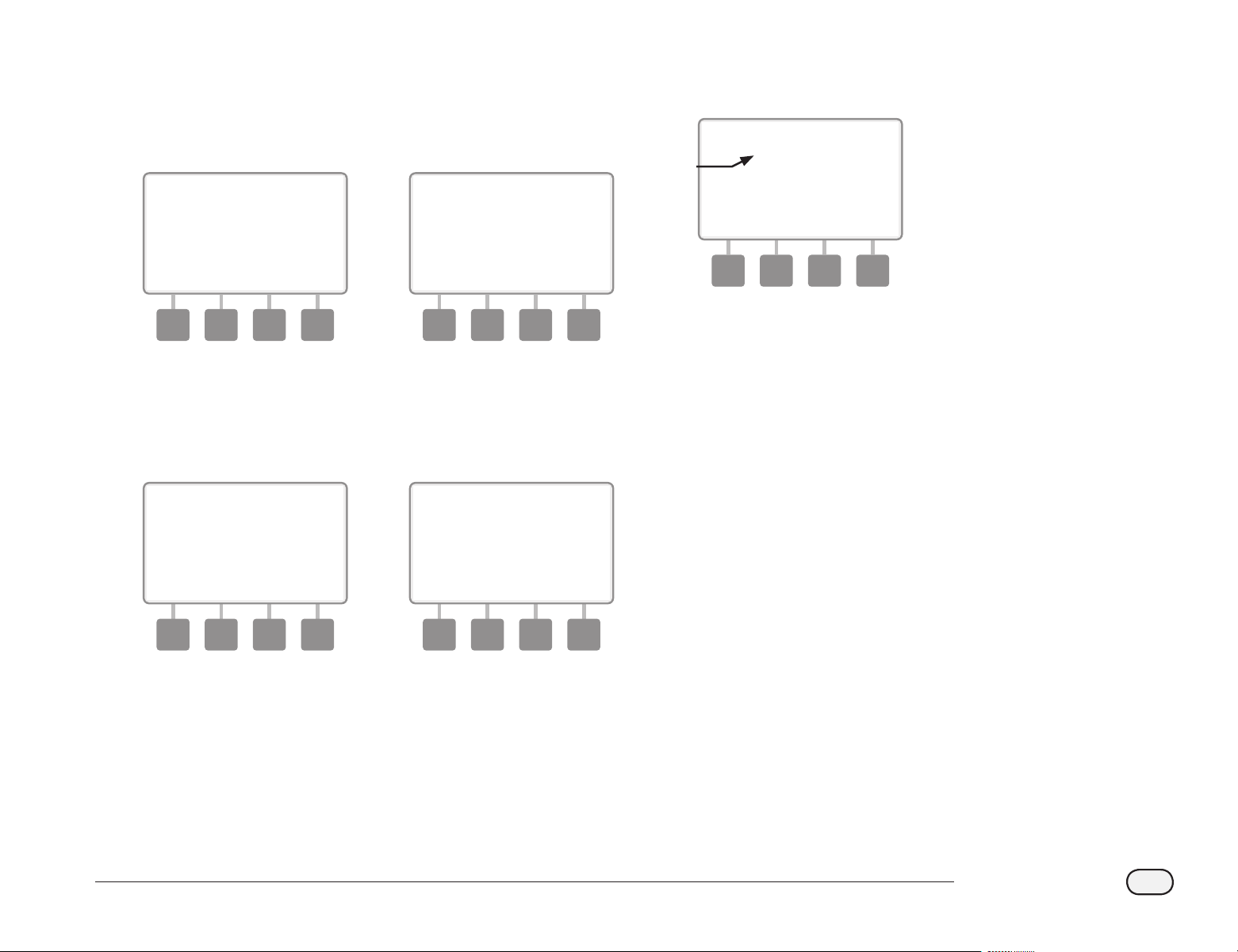
111
ESP-LXD Controller
A
From the O main screen, press the 2-Wire Path button.
B
The 2-Wire Path On/O screen will appear. Normally the 2-Wire
path will be ON, unless you have previously turned it o. Press the
O button.
1 2
C
A conrmation screen appears. To turn o the 2-Wire path, press
and hold down the Yes button for four seconds. If you’re not sure,
press No.
D
A conrmation screen appears.
3 4
E
The OFF dial position screen will now display the message “2-Wire
Path O.
5
be
Repeat this process and press the On button to restore power to
the 2-Wire path.
bb
NOTE: It’s not necessary to leave the controller dial in the OFF
position when the 2-Wire path is o. You can still change Programs
or perform other tasks. But while the 2-Wire path is powered
down, the controller’s alarm light will be lit and a 2-Wire Path O
message will be displayed whenever the controller dial is at the
OFF or AUTO dial positions.
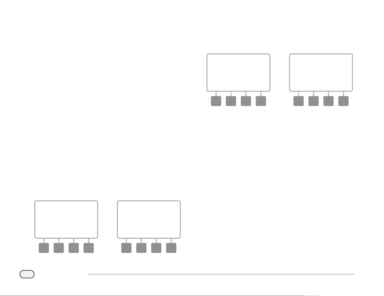
112
ESP-LXD Controller
Close Master Valves
Closes all master valves, disabling irrigation.
bd
CAUTION: Using the MV Close function will disable all irrigation
functions.
bb
NOTE: The Close Master Valves function closes Normally Open
Master Valves. Normally Closed Master Valves remain closed.
bg
Turn the controller dial to OFF.
A
The All Watering O screen appears. Press the MV Close button.
B
A conrmation screen appears. To close all master valves, press
and hold down the Yes button for four seconds. If you’re not sure,
press Back.
a b
C
A conrmation screen appears.
D
The OFF dial position screen will now display the message “All
MV’s Closed”. To cancel and restore irrigation functions, turn the
dial to AUTO.
c d

1
2
3
456
113
ESP-LXD Controller
Section H - Installation
Install the Controller
This section explains how to mount the ESP-LXD controller on a wall (or
mounting surface) and connect the wiring.
bb
NOTE: An optional metal cabinet (LXMM) and pedestal
(LXMMPED) are also available for the ESP-LXD controller. If you
intend to purchase those options then follow the installation
instructions included with those items and proceed to the Install
Modules section below.
bc
WARNING: This controller must be installed in compliance with
local electrical codes.
Installation Checklist
When installing the ESP-LXD controller for the rst time, it is
recommended that you complete the following steps in order.
For your convenience a check-o box is provided for each step.
11
Check box contents ........................................................................Page 113
11
Select a location ..............................................................................Page 114
11
Gather installation tools ...............................................................Page 114
11
Mount the controller .....................................................................Page 116
11
Install LXD module .........................................................................Page 117
11
Install expansion module(s) ........................................................Page 118
11
Connect eld wiring.......................................................................Page 119
11
Connect source power ..................................................................Page 120
11
Complete the installation ............................................................Page 122
Check Box Contents
All components below are included with your ESP-LXD controller and
are required for installation. If anything is missing, please contact your
distributor before proceeding.
A
ESP-LXD controller.
B
Mounting hardware (5 screws, 5 plastic wall anchors).
C
Controller cabinet keys.
D
ESP-LXD Controller Installation, Programming, & Operation Guide.
E
ESP-LXD Controller Programming Guide.
F
Controller mounting template.
Box Contents
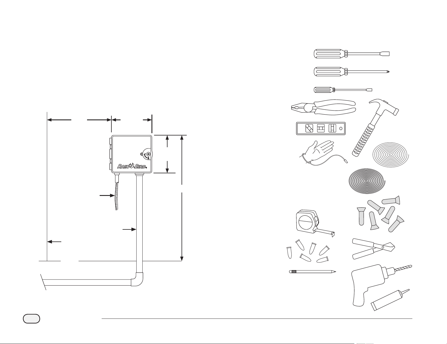
15 in.
(38,1 cm)
14.32 in.
(36,4 cm)
12.69 in.
(32,2 cm)
Eye Level
Cabinet Depth
5.5 in (14 cm)
Depending on model
120 or 220/240 V AC
wiring in conduit
Field wiring
in conduit
Wall
Grade
114
ESP-LXD Controller
Select Location for Controller
Select a location that:
bl
Is easily accessible
bl
Allows for comfortable viewing
bl
Has a at wall surface
bl
Near 120 V or 230/240 V AC power source (depending on model)
bl
Is safe from potential vandalism
bl
Is outside the range of operating sprinklers
Gather Installation Tools
Before beginning installation, gather the following tools and materials:
11
Slotted Head Screwdriver
11
Phillips Head Screwdriver
11
Thin Blade Screwdriver
11
Lineman’s Pliers
11
Torpedo Level
11
Hammer
11
Grounding Strap
11
2-Wire MAXI Cable (#14 AWG wire)
11
#8 AWG or #10 AWG Bare Ground Wire
11
3M DBR/Y Connectors
11
Tape Measure
11
Wire Stripper
11
Wire Nuts
11
Marking Pencil
11
Electric Drill (or Hammer Drill if installing
in masonry or concrete wall)
11
Waterproof Caulking
Select Controller Location

115
ESP-LXD Controller
Access Controller Cabinet
Open or Remove Controller Front Panel
A
The controller comes with an outer door lock to deter vandalism
and prevent unauthorized access to controller operations. If
necessary, unlock the cabinet door using the supplied key.
B
To open the controller door: grasp the crescent-shaped handle on
the right-hand-side of the outer cabinet.
1
2
C
Pull it towards you to open the door, swinging it to the left.
D
To open the controller front panel: grasp the crescent-shaped
handle on the right-hand-side of the front panel.
4
3
E
Pull it towards you to open the front panel, swinging it to the left.
5
F
To remove the front panel: disconnect the ribbon cable from the
front panel by gently pulling the connector out of the socket.
bd
CAUTION: Be careful not to bend the pins in the sockets when
attaching or detaching the ribbon cable.
G
Rock the front panel upward and nudge the bottom corner pin
out of the lower pin-hole to remove the front panel.
6
7
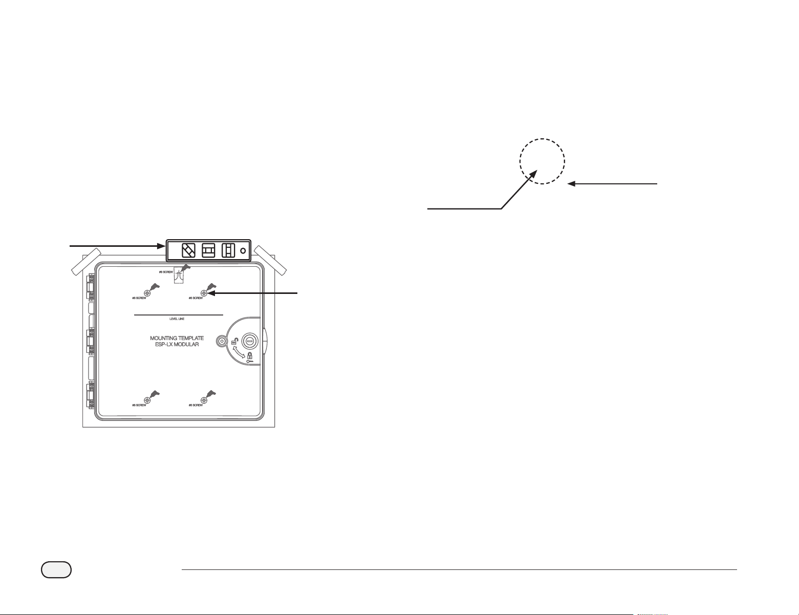
116
ESP-LXD Controller
Mount Controller
bb
NOTE: Before mounting the controller, we recommend that you
remove the controller front panel, plus decoder and/or station
modules if previously installed.
A
Using a level, tape the mounting template to the mounting
surface at approximately eye level. Make sure that at least one of
the ve mounting hole marks is aligned on a wall stud or other
solid surface.
B
Use a tapping tool (or nail) and hammer to tap pilot holes through
the ve mounting hole marks and into the mounting surface.
Then remove the template and drill holes in the mounting surface,
installing wall anchors if necessary.
1
2
5X
C
Drive the rst screw into the topmost-center hole. Then hang the
controller on the screw by the key-hole slot on the back of the
cabinet.
D
Line up the controller cabinet mounting holes with the remaining
pilot holes and drive the four remaining screws through the
cabinet back plane into the mounting surface.
3
4
4X

117
ESP-LXD Controller
Install Modules
Install LXD Decoder Module
An ESP-LXD-M50 module is required for operation and is included
with every ESP-LXD controller. The ESP-LXD-M50 module powers and
provides an interface from the controller to the two wire path.
ESP-LXD-M50 Module
The ESP-LXD-M50 module must be installed horizontally in the controller
cabinet, as shown. The module can be connected to either the top set
of connectors (module slots 1 and 3) or the bottom set of connectors
(module slots 2 and 4) on the controller backplane. We recommend
installing the module into the top set of connectors unless you plan to
upgrade your controller with an optional ET Manager cartridge. If you
plan to add the ET Manager then we recommend installing the module
into the bottom set of connectors to allow more space for installation
and cable routing of the ET Cartridge Receiver (antenna).
bd
CAUTION: Be careful not to bend the pins in the sockets when
installing the module.
A
Orient the connectors on the bottom of the module with the
connection sockets on the controller backplane.
1
B
Carefully fasten the module onto the controller backplane,
pressing rmly until it snaps into place.
C
Connect the green ground wire to the ground post on the left side
of the controller backplane.
3
2
bb
NOTE: To remove the module again, press in on the (four) release
buttons on either side of the module.

118
ESP-LXD Controller
Install Station Expansion Modules
The ESP-LXD controller comes standard with 50 stations available. This
can easily be expanded by adding one or two optional ESP-LXD-SM75
Station Modules. Each station module adds 75 additional stations to
increase capacity to 125 or 200 stations.
Once your LXD Decoder module
is correctly installed, you’ll notice
that two additional module
slots are still available. Each of
these module slots can accept
one station module. Follow the
instructions to install one or two
station modules. The controller
will automatically recognize the
additional station capacity.
bd
CAUTION: Be careful not to bend the pins in the sockets when
installing the module.
A
Orient the connector on the bottom of the SM75 module with a
connection socket on the controller backplane.
1
B
Carefully fasten the module onto the controller backplane,
pressing rmly until it snaps into place.
2
bb
NOTE: To remove the module again, press in on the (two) release
buttons on either side of the module.
Connect Field Wiring
The ESP-LXD controller can support up to four 2-Wire connections.
The controller will manage multiple 2-Wire connections as a single
2-Wire path. The cable must be approved for underground use.
Rain Bird recommends use of MAXI Cable, #14 AWG, as your 2-Wire
communications cable.
Connecting the 2-Wire Cable
bb
NOTE: If installing communications wiring for IQ Software and/
or ET Manager, do not install the communications cables in the
same conduit as the 2-Wire path wiring.
A
Strip away approximately 6 in (15,24 cm) of the cable’s outer
sheathing; then strip approximately 5/8 in (1,58 cm) of the
insulation away from the ends of the two inner wires. See Wire
Splices and Field Decoder Connections for more details on the
correct way to splice wire connections.
ESP-LXD-SM75 Station
Expansion Module
119
ESP-LXD Controller
B
Locate (or remove) the large knockout on the bottom of the
controller cabinet. Attach a conduit tting to the bottom of the
cabinet; then attach conduit to the tting.
C
Feed the 2-Wire communications cable through the conduit and
into the controller cabinet.
2
3
D
Using a thin blade screwdriver, connect the two wire ends to a
set of large two-wire path terminals on the ESP-LXD decoder
module. When nished, tug gently on the wires to make sure the
connections are tight.
4
be
If you have multiple two wire paths then repeat this process to
connect those wire ends to the other LXD module terminals as
desired.
E
Once wiring is completed, ll top of conduit with waterproof
caulking to prevent insect intrusion into the controller cabinet.
5
120
ESP-LXD Controller
Connecting Power to the Controller
Connect Ground Wire
The ESP-LXD controller is equipped with built-in electrical surge
protection. For this system to function, you must properly ground the
controller.
bc
WARNING: The ground wire MUST be connected to provide
electrical surge protection. Connect the controller to the
grounding grid using at least a #8 AWG (10 mm) or #10 AWG
(6 mm) bare copper wire. The wires should be as short and as
straight as possible. You will void the controller warranty if you do
not ground the controller to a minimum resistance of ve ohms.
Connect Power Source
The ESP-LXD controller has an internal transformer that reduces supply
voltage (120 VAC in U.S. models; 230 VAC in international models; 240
VAC in Australian models) to 24 VAC to operate the decoders connected
to the controller. You will need to connect power supply wires to the
transformer’s three wires.
bc
WARNING: Electric shock can cause severe injury or death. Make
sure power supply is turned OFF before connecting power wires.
bc
WARNING: All electrical connections and wiring runs must be
made according to local building codes.
A
With the front panel removed, locate the transformer wiring
compartment in the lower left corner of the controller cabinet.
Remove the screw on the right-hand side and pull the cover o to
expose the wiring compartment.
1
Wiring Connections
120 VAC (US) 230 VAC (International)
Black supply wire (hot) to the black
transformer wire
Black supply wire (hot) to the black
transformer wire
White supply wire (neutral) to the
white transformer wire
Blue supply wire (neutral) to the
blue transformer wire
Green supply wire (ground) to the
green transformer wire
Green-with-yellow-stripe supply
wire (ground) to the green-with-
yellow-stripe transformer wire
121
ESP-LXD Controller
B
Strip the insulation from the three incoming wires to expose
approximately 1/2 in (13 mm) of bare wire.
C
Remove the knockout on the bottom of the cabinet below the
transformer and attach a 1/2 in (13 mm) conduit tting to the
bottom entrance of the wiring compartment.
bb
NOTE: 240 VAC (Australian) units do not require a conduit
because the power supply cable is already installed.
D
Feed the three supply wires from the power source through the
conduit into the wiring compartment.
3
4
2
3X
3 wires
E
Using wire nuts, connect the wires accordingly.
5
3X
bc
WARNING: The ground wire MUST be connected to provide
electrical surge protection. You will void the controller warranty if
you do not ground the controller.
F
Once wiring is completed, ll top of conduit with waterproof
caulking to prevent insect intrusion into the controller cabinet.
6
G
Verify that all connections are secure. Then replace the cover of
the transformer wiring compartment and secure it with the screw.
122
ESP-LXD Controller
Complete Installation
bc
WARNING: To prevent electrical shock, make sure all supply
power is OFF before completing installation. Electrical shock can
cause severe injury or death.
A
If you removed the front panel, reinstall it now by inserting the
top corner pin into the top pin-hole; then push up and rock the
bottom corner pin into the lower pin-hole.
B
Reconnect the ribbon cable to the front panel by gently pushing
the connector into the socket.
bd
CAUTION: Be careful NOT to bend the pins in the socket.
2
1
C
Turn on the power source.
bb
NOTE: The rst time you power up the controller, the display will
prompt you to select the language you wish to use. See Section E,
Set Language for more details..
Programming Under Battery Power
The ESP-LXD controller front panel can operate under battery power for
remote programming. This feature is especially useful if the controller
is installed in an area that is not easily accessible. It also lets you enter
program information before installing the controller at the job site.
All program information is stored in nonvolatile memory so it will be
preserved indenitely in the event of a power outage.
bb
NOTE: Under battery power, all programs in progress will
continue to run in memory, but irrigation will not occur until
power is restored. Without battery power, remaining programs
will be cancelled.
D
Install a new 9-volt battery in the battery compartment in the
back of the front panel.
4
bb
NOTE: To perform remote programming, detach the front panel
from the cabinet. See Access Controller Cabinet for more details.
bd
CAUTION: The controller can not run irrigation or system
diagnostics with the front panel detached. Re-connect the front
panel to the controller’s AC power source as soon as remote
programming is completed.
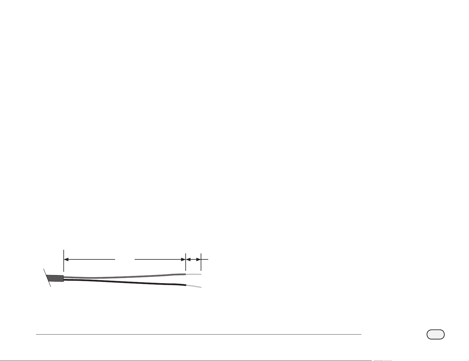
123
ESP-LXD Controller
Connect Decoders to Field Wiring
All valves must be connected to eld decoders for irrigation
management by the controller. Decoders must be wired both to a valve
and by splicing to the 2-Wire path. Splices and eld decoders should
always be placed in valve boxes (except when valve-in-head sprinklers
are used, which can be directly buried).
bb
NOTE: Before installing eld decoders, remove the barcode
address label from each decoder and attach it to the proper
station (or device) number eld in the Programming Guide. See
Programming Guide instructions for more details.
Wire Splices
bb
NOTE: Label any wires that will be spliced in case troubleshooting
is required later.
A
Strip away approximately 6 in (15,24 cm) of the cable’s outer
sheathing. Rain Bird recommends use of a MAXI cable jacket
stripper for this task. The stripping should be done by carefully
scoring the outer jacket in at least two places and then gently
exing the cable to loosen the portion of the outer jacket to be
removed. It may be necessary to remove the outer jacket in two
or more sections.
B
Once the red and black inner wires are exposed, use a wire stripper
to strip approximately 5/8 in (1,58 cm) of the insulation away from
the ends of the two inner wires.
1 2
5/8 in
(1,58 cm)
6 in
(15,24 cm)
Splice for 2-Wire Cable
C
If a splice is needed to support an additional connection to MAXI
cable, connect the inner red wire to the additional cable red
wire and the black wire to the black wire, using linesman’s pliers
to gently twist the wires together three or four times. Insert the
connections into an approved direct bury splice kit.
bc
WARNING: Use only Rain Bird DB (direct burial) or 3M DBR/DBY
splice kits for all electrical wiring connections to the 2-Wire path.
Improper wiring can cause serious damage to your controller or
irrigation system.
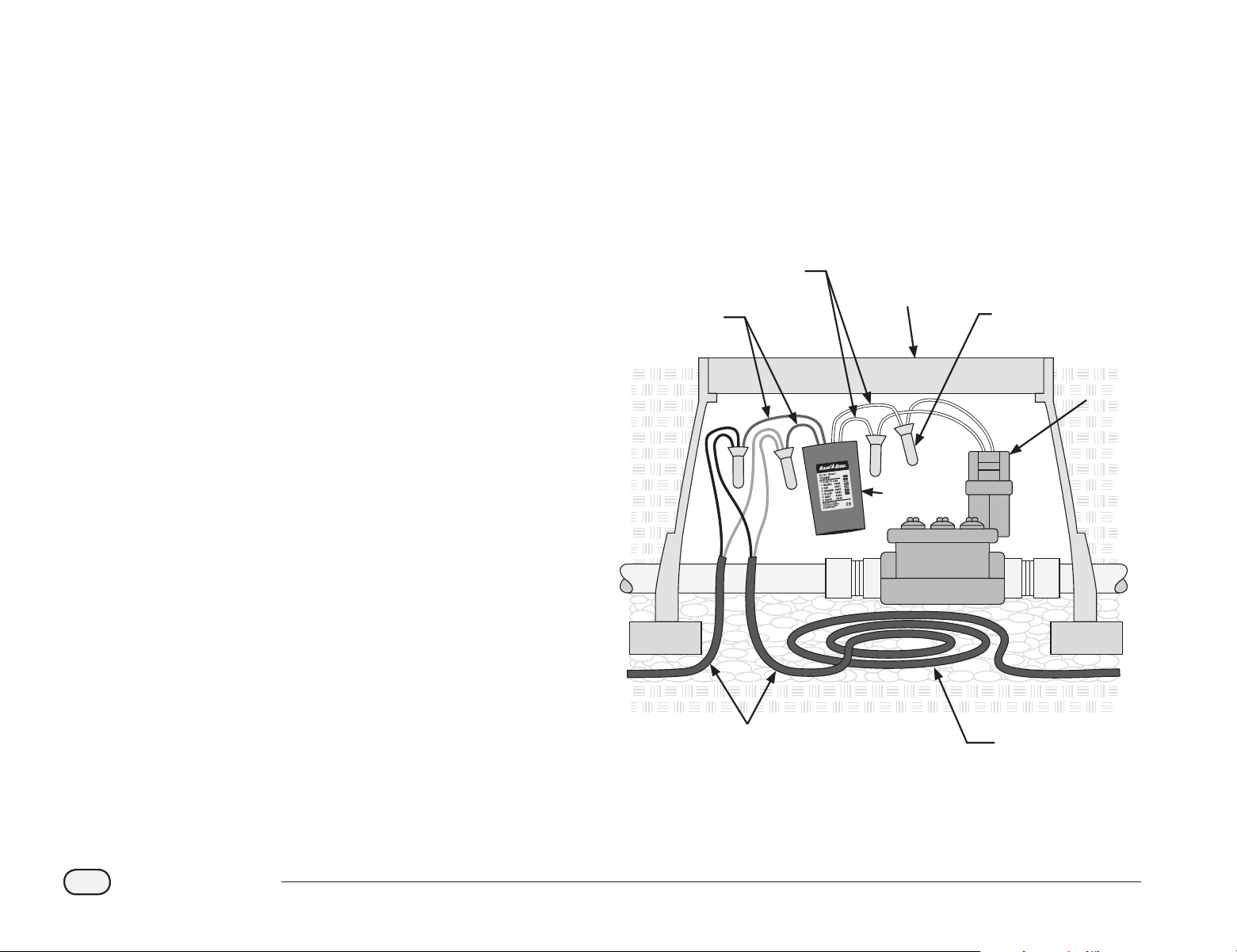
Line
Wires
3M DBR/Y
Connectors
Valve
Box
Valve
(Solenoid)
Decoder
2-Wire
Cable
Allow 3’
Extra Cable
Length
1
Output
Wires
2
3
4
124
ESP-LXD Controller
Field Decoder Connections
A
Splice one decoder blue wire to the 2-Wire path red wire; then
splice the other decoder blue wire to the 2-Wire path black wire.
If the decoder is NOT at the end of the two wire path then make a
three-way splice; one blue wire from the decoder to the two red
wires in the two wire path; then splice the other blue decoder
wire to the two black wires in the two wire path.
B
Splice additional wires from the decoder to the valve or valves to
be controlled, using a pair of the same color wires for each valve.
For example, Rain Bird FD-101 eld decoders control a single
valve and have a pair of white wires for connection to the valve.
Other Rain Bird eld decoders are capable of controlling multiple
valves. For example, the FD-601 has six additional pairs of wires
for connection to up to six dierent valves.
bb
NOTE: When using eld decoders capable of controlling multiple
valves, note the wire color combination and decoder address
combinations on the side of the decoder. Be sure to connect
the wires to the dierent valves in the order you want your
valves controlled, and be sure to ax the decoder labels to your
Programming Guide in the same order.
C
Complete the splices to each valve by inserting the eld decoder-
to-valve splices into an approved direct bury splice kit.
bc
WARNING: Use only 3M DBR/Y splice kits for all electrical wiring
connections to the 2-Wire path. Improper wiring can cause serious
damage to your controller or irrigation system.
D
For future troubleshooting or modications, it is recommended
to leave an additional 3 feet of 2-Wire cable stored in each valve
box location.
bb
NOTE: For secondary wire run, the distance between the eld
decoder and the solenoid (valve) can not exceed 450 feet (137
meters) using 14 gauge wire.
Typical Field Decoder Wiring
Master Valves and MV Decoders
Up to ve master valves can be connected to the ESP-LXD controller
through eld decoders attached to the two wire path. Master valves
are connected to eld decoders using the same processes as described
previously. Be sure to attach the decoder barcode label to the
Programming Guide as a master valve decoder instead of a normal
station decoder.

125
ESP-LXD Controller
Surge Protection and Grounding
bc
WARNING: The ESP-LXD controller and the 2-Wire path must
be properly surge protected and grounded. Doing so can help
prevent damage to the controller and irrigation system and also
signicantly reduce troubleshooting, repair time and expense.
Failure to do so could result in failure of your controller and
voiding the warranty.
Rain Bird requires the 2-Wire path to be surge protected and grounded
with one LSP every 500 feet or every 8 decoders, whichever is smaller.
Ensure that all grounding devices are compliant with local electrical
codes.
Install Lightning Surge Protectors (LSP-1s)
A
Using a design drawing or as-built diagram for your installation
system, determine the number of LSP-1s required and where they
will need to be installed.
B
At the rst LSP-1 location, install a grounding device, typically
a grounding rod or plate, which meets all local codes, near the
2-Wire path.
C
Splice the blue wires from a Rain Bird LSP-1 to the 2-Wire path in
the same manner as the installation of a eld decoder detailed
above, completing the splices with an approved direct-bury
splice kit.
D
Connect the ground wires from the LSP-1 to the grounding device
and install the LSP-1 inside a valve box.
E
Repeat this process to install all other LSP-1s as needed, noting
their locations on your as-built diagram and/or design drawings.
bb
NOTE: LSP-1s do not have decoder addresses, so it’s not necessary
to capture this information from your LSP-1s. For this reason, LSP-
1s also do not have peel-o barcode labels for the Programming
Guide. LSP-1s do not need to be recognized by or programmed
into the controller or noted on the Programming Guide.

126
ESP-LXD Controller
Decoder Managed Flow Sensors
Flow sensors are managed with SD-211 sensor decoders attached
to the 2-Wire path. The ESP-LXD controller can support and manage
up to five flow sensors.
Connect Flow Sensors
A
Install the ow sensors into your irrigation piping system.
bb
NOTE: For optimum performance and ow sensing, ow sensors
should be installed a minimum of 10 pipe diameters in length on
the upstream (supply) side and a least 5 pipe diameters in length
on the downstream (delivery) side before making any transitions
in pipe size/direction or away from any valve.
B
For flow sensing, a Rain Bird SD-21
1 sensor decoder should be
used in a valve box with proximity to a grounding device, the
2-Wire path and the ow sensor.
bb
NOTE: If a grounding device is not present, install one, ensuring
compliance to all local codes.
C
Follow the eld decoder installation process to splice the two
blue wires from the ow sensor to the red and black wires in the
two wire path, completing the splice with approved direct burial
splice kits.
D
Attach the green and yellow wires from the sensor decoder to the
grounding device.
E
Splice the red and black wires from the SD-211
sensor decoder
to the ow sensor. Be sure to follow all instructions included with
the ow sensor. Complete the splices with approved direct burial
splice kits.
F
Carefully peel the sensor decoder barcode label o of the
sensor decoder and ax it into the ow sensor section of the
Programming Guide.
Decoder Managed Weather Sensors
In addition to five flow sensors, ESP-LXD can also support three
decoder-managed weather sensors. Rain Bird SD-211 sensor decoders
are used and installed in exactly the same way. To install decoder-
managed weather sensors, repeat this process but connecting the
SD-211 sensor decoder to the weather sensor instead of to a flow
sensor.

127
ESP-LXD Controller
Local Weather Sensors
ESP-LXD can also accept input from a single weather sensor wired
directly in to the controller instead of to the 2-Wire path. Supported
Rain Bird sensors include the RSD rain sensing device, the WR2-RC
wireless rain sensor, the WR2-RFC wireless rain/freeze sensor and the
ANEMOMETER wind sensor (the Rain Bird 3002 Pulse Transmitter is
required for use of the ANEMOMETER). Other generic sensors, such as
soil moisture sensors will also typically work. ESP-LXD supports one
local weather sensor. The local weather sensor can also be bypassed
with the sensor bypass switch on the controller front panel.
Connect Local Weather Sensors
bb
NOTE: Follow the sensor manufacturer’s instructions to correctly
install and make wire connections to the sensor. Ensure the sensor
installation is in compliance with all local codes.
A
Run continuous sensor wires from the weather sensor to the ESP-
LXD controller.
B
Remove the yellow jumper wire (if present). Connect the sensor
wires to the sensor (Sen) and common (C) inputs, to the right of
the 2-Wire path terminals on the ESP-LXD decoder module. When
nished, tug gently on the wires to make sure the connections
are tight.
2
bb
NOTE: If your weather sensor requires 24V power from the
controller, the connectors to the left of the sensor and common
connectors can be used.
C
To enable the weather sensor: on the controller front panel, slide
the Weather Sensors switch to Active.
3
bb
NOTE: Ensure that the conguration for your controller and
irrigation programs are set up correctly for your sensor. For
example, if one of your programs is set up to manage your
landscape lighting you may want to ensure that its stations ignore
input from a local rain sensor. See Section B, Weather Sensors
Setup for more details.
bb
NOTE: The Weather Sensors switch activates or bypasses all
installed weather sensors on your system.
Verifying Field Installation
Once some or all eld decoders have been installed and programmed
into the ESP-LXD controller you can check the electrical portion of the
installation even if water is not available to test sprinklers. See Section
C, Run a Line Survey for more details.
If water is available and you would like to test some or all of your
sprinklers, the easiest way to do so is by using the Manual Watering
features of the controller. See Section G, Manual Watering for more
details.

128
ESP-LXD Controller
this page intentionally left blank
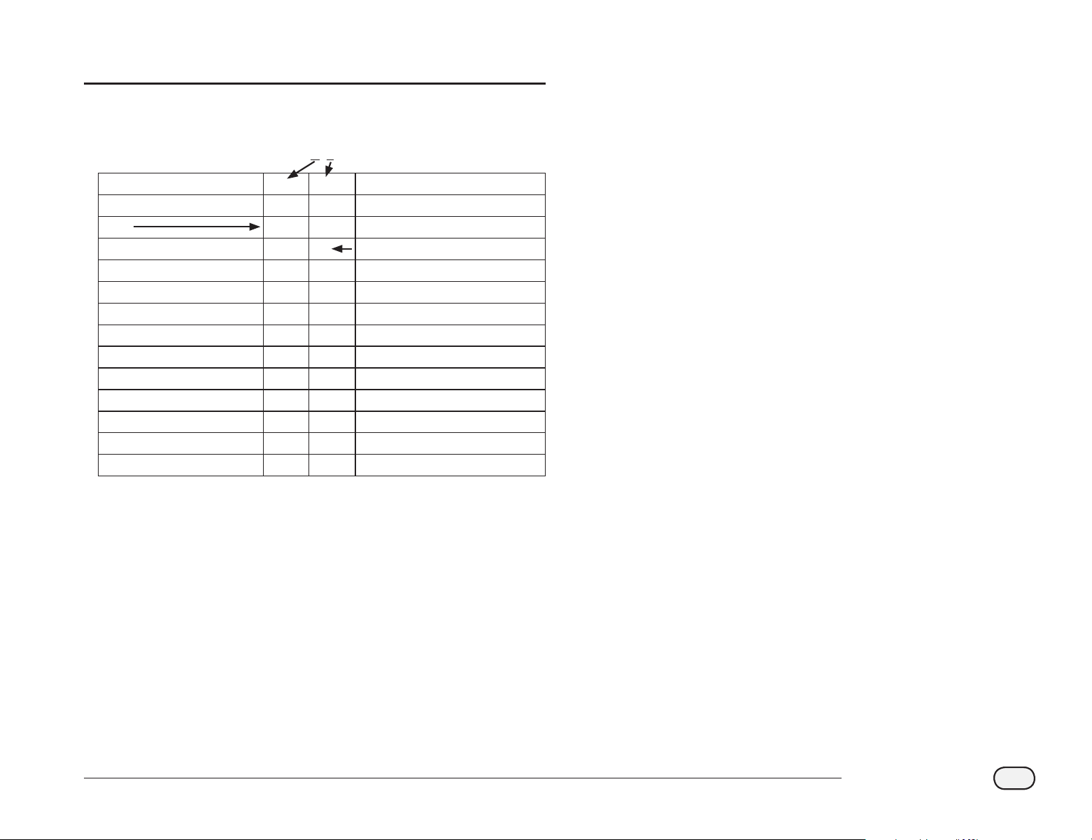
129
ESP-LXD Controller
Appendix
Electrical Requirement Code of Magnetic Solenoid
Activation Time [ms] X Y Holding Voltage [Volts]
30 3 3 1.2
40 4 4 1.7
50 5 5 2.3
60 6 6 2.9
70 7 7 3.5
80 8 8 4.0
90 9 9 4.6
100 A A 5.2
110 B B 5.8
120 C C 6.3
130 D D 6.9
140 E E 7.5
150 F F 8.1
SWITCH CODE DEFINITION 59 F, X, Y, 0
Use the chart above to select a suitable electrical code for special
solenoid (valve) types.
bb
NOTE: To nd a switch code that works with your valve, you may
need to use the trial and error method.
Example:
Arrows in chart show:
Activation Time = 40 ms. (milliseconds)
Holding Voltage = 2.3 volts
Switch Code = 59F450
If the solenoid opens but will not stay open, the holding voltage may
be too low. Here, you would change the fth digit of the code.
Example:
Arrows in chart show:
Activation Time = 50 ms.
Holding Voltage = 5.2 Volts
Switch Code = 59F5AO
If the solenoid opens but will not stay open, the holding voltage may
be too low. Here, you would change the fth digit of the code.
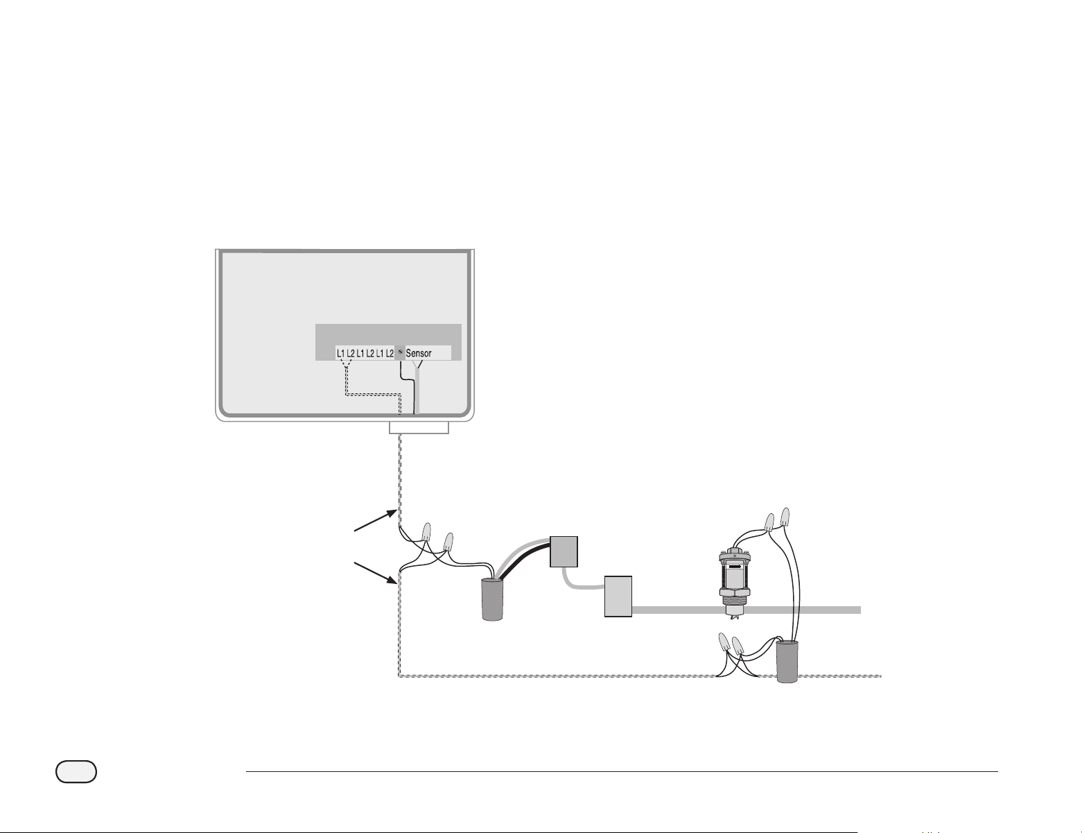
FLO W
ESP-LXD Controller
2-Wire
Communications
Cable
Pump Start Relay
Pump
Field Decoder
Flow
Sensor
Water Line
Sensor Decoder
130
ESP-LXD Controller
Master Valve and Pump Set-up Tips
To supply water to the various valves located throughout an irrigation
area, systems may use either a master valve or master pump. By
recognizing a specic Address and switch code, the controller sends a
signal telling the decoder when to activate the master valve or pump.
The switch code can vary depending on how your system was installed.
Below, we will cover some of the more common installations.
Using a Field Decoder With a Pump Start Relay
In this installation, a eld decoder attaches to a pump using a pump
start relay. When setting up the controller, enter the eld decoder
Address in the master valve Address eld.
bb
NOTE: Rain Bird recommends use of a FD-101 for small pump
start relays and a FD-102 for pumps 3/4 HP or greater.

Declaration of Conformity
Application of Council Directive: 2004/108/EC
Standards To Which
Conformity Is Declared:
EN55014-1: 2001 Class B
EN55022 Radiated Emissions
EN55022 Conducted Emissions
EN61000-3-2
EN61000-3-3
EN55014-2: 2001
EN61000-4-2
EN61000-4-3
EN61000-4-4
EN61000-4-5
EN61000-4-6
EN61000-4-8
EN61000-4-11
Manufacturer’s Name:
Rain Bird Corporation
Manufacturer’s Address:
9491 Ridgehaven Court
San Diego, CA 92123
619-671-4048
Equipment Description:
Irrigation Controller
Equipment Class:
Requirements for household
appliances, electric tools and
similar apparatus
Model Numbers:
ESP-LXD
I the undersigned, hereby declare that the equipment specied
above conforms to the above Directive(s) and Standard(s).
Place:
Tucson, AZ USA
Signature:
Full Name:
Ryan L. Walker
Position:
Director

RAIN BIRD CORPORATION
6991 E. Southpoint Road
Tucson, AZ 85756
© 2012 Rain Bird Corporation
®
”Rain Bird”, “SimulStations”, “FloManager”, “FloWatch”, “FloZone” and “Cycle+Soak”
are registered trademarks of Rain Bird Corporation. All rights reserved.
www.rainbird.com
Jan-2012 P/N: 637760-01
