11
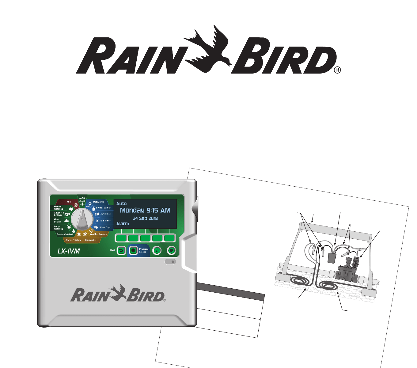
ESP-LXIVM Series Controllers
IVM-OUT (Output Device)
IVM-OUT 2-Wire control devices can be used
to control valves with DC latching solenoids.
A
Connect the red and black wires on the IVM-
OUT to the 2-Wire Path.
B
Connect the red/white striped wire on the
IVM-OUT to the DC latching solenoid red
wire.
Connect the black/white striped wire on the
IVM-OUT to the DC latching solenoid black
wire.
C
For future troubleshooting or modifications,
it is recommended to leave an additional 3
feet (1 meter) of 2-Wire cable stored in each
valve box location.
B
NOTE: Make sure that the DC latching sole-
noid is compatible with non Rain Bird valves.
Contact the valve manufacturer for more
information.
NOTICE
Maximum combined wire length between IVM-
OUT and its load (e.g. Solenoid) shall be 48 in.
This includes pre-installed IVM-OUT wire (24 in.)
and solenoid wires (22 in.).
Use only WC20 splice kits for all wiring
connections to the 2-Wire Path. Improper wiring
can cause serious damage to your controller or
irrigation system.
Non-Rain Bird
valve with DC
Latching Solenoid
Valve
Box
2-Wire
Cable
Allow 3 ft. (1 m)
Extra Cable
Length
A
C
IVM-OUT
B
Typical IVM-OUT Wiring
ESP-LXIVM Series Controllers
Field Device Installation Guide
2
ESP-LXIVM Series Controllers
Regulatory Information
Federal Communications Commission
Supplier’s Declaration of Conformity
47 CFR § 2.1077 Compliance Information
Unique Identifier:
ESPLXIVM, ESPLXIVMP, LXIVMFP, LXIVMPFP, LXIVMSOL, LXIVMOUT,
LXIVMSEN, LXIVMSD
Responsible Party – U.S. Contact Information
Rain Bird Corporation
9491 Ridgehaven Court
San Diego, CA 92123 USA
www.rainbird.com
FCC Compliance Statement
This device complies with part 15 of the FCC Rules. Operation is subject to the following
two conditions: (1) This device may not cause harmful interference, and (2) this device
must accept any interference received, including interference that may cause undesired
operation.
Note: This equipment has been tested and found to comply with the limits for a Class
B digital device, pursuant to part 15 of the FCC Rules. These limits are designed to pro-
vide reasonable protection against harmful interference in a residential installation. This
equipment generates, uses and can radiate radio frequency energy and, if not installed
and used in accordance with the instructions, may cause harmful interference to radio
communications. However, there is no guarantee that interference will not occur in a
particular installation. If this equipment does cause harmful interference to radio or tele-
vision reception, which can be determined by turning the equipment off and on, the
user is encouraged to try to correct the interference by one or more of the following
measures:
• Reorient or relocate the receiving antenna.
• Increase the separation between the equipment and receiver.
• Connect the equipment into an outlet on a circuit different from that to which the
receiver is connected.
• Consult the dealer or an experienced radio/TV technician for help.
IC Canada Statement
The Class B apparatus meets all requirements
of the Canadian ISED (formerly IC) regulations
- CAN ICES-3 (B)/NMB-3 (B).
Cet appareil de classe B respecte toutes les exi-
gences de la réglementation canadienne ISED
(anciennement IC)- CAN ICES-3 (B)/NMB-3 (B).
Waste Electrical and Electronic
Equipment (WEEE)
As a hardware manufacturer, Rain Bird has
met its national obligations to the EU WEEE
Directive by registering in those coun-
tries to which Rain Bird is an importer. Rain
Bird has also elected to join WEEE Compli-
ance Schemes in some countries to help
manage customer returns at end of life.
Certifications
• cULus, CE, NOM, RCM, IRAM,
INMETRO, NRCS, SABS, KC
3
ESP-LXIVM Series Controllers
2020 Rain Bird Corpora�on
Registered Trademark of Rain Bird Corpora�on
P/N: 690865-01 REV. 08JA20
DECLARATION OF CONFORMITY
Rain Bird Corpora�on hereby declares that the following irriga�on controllers and accessories are CE compliant.
IESPLXIVM, IESPLXIVMP, ILXIVMEU, ILXIVMPEU, LXIVMSOL, LXIVMOUT, LXIVMSEN, LXIVMSD, LXIVMPFP*, LXIVMFP*, and LXIVM2WMOD*
(*Spare part sold separately - obtained compliance with the controller IESPLXIVM)
This declara�on of conformity is issued under the sole responsibility of the manufacturer. The object of the declara�on described above is in
conformity with the relevant Union harmoniza�on legisla�on, and the references to the relevant harmonized standards used or to other technical
specifica�ons in rela�on to which conformity is declared are listed below:
Electromagne�c Compa�bility (EMC) Direc�ve 2014/30/EU
• EN 55014-1:2006 + A2:2011
• EN 55014-2:1997
+ A1:2001 + A2:2008
Low Voltage (LVD) Direc�ve 2014/35/EU
• EN 60335-1:2012 + AC:2014 + A11:2014 + A13:2017 including
• IEC 60335-1:2010, and EN 62233:2008 + AC:2008
• IEC 60335-1 Edi�on 5.2: 2010 +A1: 2013 +A2: 2016
Restric�on of the use of certain Hazardous Substances (RoHS) Direc�ve 2011/65/EU
• EN 50581:2012
Place:
San Diego, CA
Signature:
Full Name:
Roger S. Neitzel
Posi�on:
Plant and Program Manager
Date:
January 8, 2020
Rain Bird Corpora�on
970 W. Sierra Madre Ave.
Azusa, California 91702, USA
Phone: (626) 812-3400
Fax: (626) 812-3411
Rain Bird Interna�onal, Inc.
1000 West Sierra Madre Ave.
Azusa, CA 91702, USA
Phone: (626) 963-9311
Fax: (626) 852-7343
Rain Bird Europe
240 Rue René Descartes – Le Clamar Bât. A
13290 Aix En Provence, France
Phone: (33) 4 42 24 44 61
Fax: (33) 4 42 24 24 72
4
ESP-LXIVM Series Controllers
Safety Information
CWARNING
Special precautions must be taken
when valve wires (also known as
station or solenoid wires) are located
adjacent to, or share a conduit with
other wires, such as those used
for landscape lighting, other “low
voltage” systems or other “high
voltage” power.
Separate and insulate all conductors
carefully, taking care not to damage
wire insulation during installation.
An electrical “short” (contact)
between the valve wires and
another power source can damage
the controller and create a fire
hazard.
All electrical connections and
wiring runs must comply with
local building codes. Some local
codes require that only a licensed
or certified electrician can install
power. Only professional personnel
should install the controller. Check
your local building codes for
guidance.
CCAUTION
This appliance is not intended for
use by persons (including children)
with reduced physical, sensory
or mental capacity, or lack of
experience and knowledge unless
they have been given supervision
or instruction concerning use of the
appliance by a person responsible
for their safety. Children should
be supervised to ensure that they
do not play with the appliance.
Cleaning and user maintenance shall
not be made by children without
supervision.
If the supply cord of ILXIVMAU or
ILXIVMAUP is damaged, it must be
replaced by the manufacturer, its
service agent or similarly qualified
persons in order to avoid a hazard.
Replace with the following:
Flexible supply cord H05VVF,
minimum wire size of 0.75 mm^2 (18
AWG).
For direct connection wiring:
Minimum wiring size is 0.75 mm^2
(18 AWG).
For controllers not provided with a
supply cord, the fixed installation
must include a disconnecting
device for all three poles suitable for
overvoltage category III protection.
NOTICE
Use only Rain Bird approved
accessory devices. Changes or
modifications not expressly
approved by Rain Bird could void
the user’s authority to operate the
equipment. Unapproved devices
may damage the controller and void
the warranty. For a list of compatible
devices go to: www.rainbird.com
Date and time are retained by a
lithium battery which must be
disposed of in accordance with local
regulations.
Model, serial number, supply rate
and fabrication date are located on
the back of swing panel.
Power supply for countries with 120V
Input: 120 V ac 60 Hz 0.5A
Output: 26.5 V ac 60 Hz 1.9A`

5
ESP-LXIVM Series Controllers
2-Wire Device Field Connections ....................................... 6
Gather Installation Tools ................................................................................. 6
Wiring Connections ......................................................................................... 6
Outdoor Installation with Direct Wiring ....................................................................6
Field Wiring Connections ........................................................................................... 7
Connect devices to the 2-Wire path. ................................................................................. 7
Installation ....................................................................................................... 8
2-Wire Address Labels ................................................................................................8
IVM-SOL Installation ................................................................................................... 9
Connect IVM-SOL to a Valve ............................................................................................... 10
Connect IVM-SOL to a Master Valve .................................................................................. 10
IVM-OUT (Output Device) ...........................................................................................11
IVM-SEN (Sensor Device) ............................................................................................ 12
Connect Weather Sensors ................................................................................................... 12
IVM-SD (Surge Device) ................................................................................................ 13
Pump Start Relay .........................................................................................................14
Connect 2-Wire (MAXI Cable) From Field Devices ......................................... 15
Connect Local Weather Sensors ...................................................................... 15
ESP-LXIVM Series Controllers
Field Device Installation Guide
6
ESP-LXIVM Series Controllers
2-Wire Device Field Connections
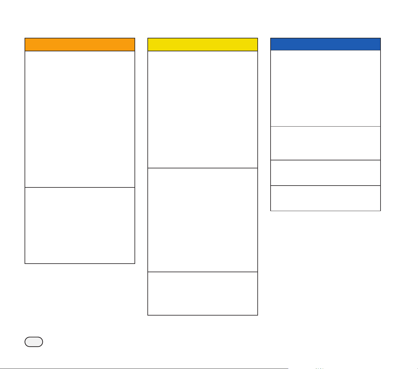
Gather Installation Tools
Before beginning installation, gather together the
following tools and materials:
L
Lineman’s pliers
L
#14 AWG MAXI Cable
bare ground wire
L
WC20 waterproof wire connectors
and wire nuts (provided)
L
Rain Bird® 2-Wire stripper
Wiring Connections
Outdoor Installation with Direct Wiring
CWARNING
Electric shock can cause severe injury or death. Make sure
power supply is turned OFF before connecting power
wires.
Ground wire must be connected to provide electrical
surge protection. Permanently mounted conduit shall be
used for connecting main voltage to the controller.
Do not route valve wires through the same opening as
power wires.
Wiring Connections
120 VAC (US) 230 VAC (International)
Black supply wire (hot) to
the black transformer wire
Brown supply wire (hot) to
the brown transformer wire
White supply wire (neutral)
to the white transformer
wire
Blue supply wire (neutral) to
the blue transformer wire
Green supply wire
(ground) to the green
transformer wire
Green-with-yellow-stripe
supply wire (ground) to the
green-with-yellow-stripe
transformer wire
A
Route the three external power source wires through
the conduit opening at the bottom of the unit and into
the wiring compartment.
B
Using the provided wire nuts, connect the external
power source wires (two power and one ground) to
the transformer connection wires inside the wiring
compartment.
B
7
ESP-LXIVM Series Controllers
Field Wiring Connections
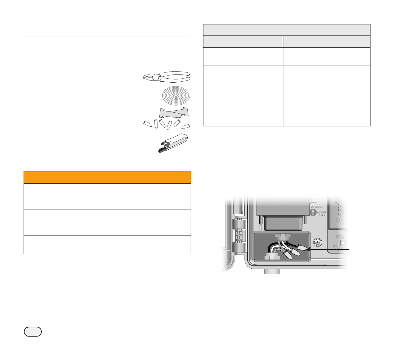
Connect devices to the 2-Wire path.
Rain Bird
2-Wire
Stripper
It is recommended to use the Rain
Bird 2-Wire Stripper tool to remove
the outer MAXI Cable jacket without
damaging the inner insulation.
B
NOTE: To avoid damaging the wiring, tools such as util-
ity, pocket, carpet, box cutter knives or Romex strip-
pers should not be used to strip wires.
NOTICE
Rain Bird requires the use of 14 gauge AWG MAXI Cable
(double-jacketed, 2-Wire conductor).
Always place 2-Wire Devices and connections inside a
valve box. Assure that the wiring copper conductors are
not exposed after installation.
A
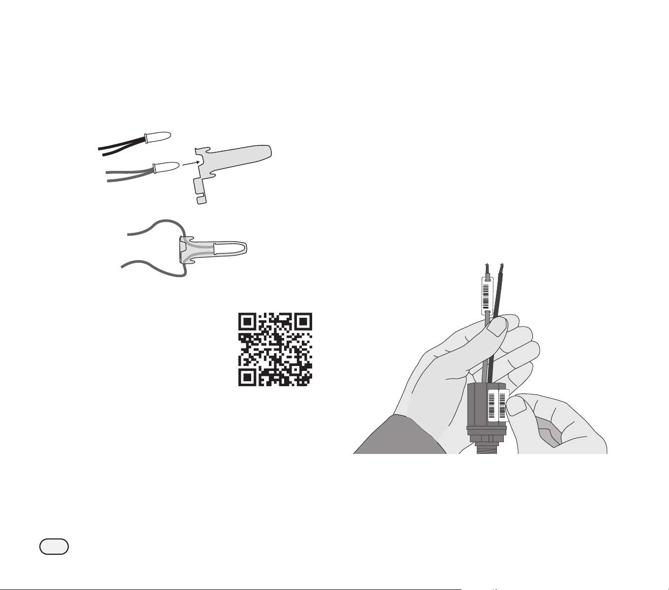
Carefully score approximately 6 in (15,24 cm) of the
AWG MAXI Cable’s outer jacket . Gently flex the cable
to expose the portion to be removed and to reveal the
2 inner wires. Then trim away the excess of the outer
jacket.
B
NOTE: It may be necessary to remove the outer jacket
in two or more sections.
A
B
Strip away approximately 5/8 in (1,58 cm) of insulation
from the ends of the two inner wires.
5/8 in
(1,58 cm)
6 in
(15,24 cm)
No nicks or cuts to
inside wire
No scratches
B
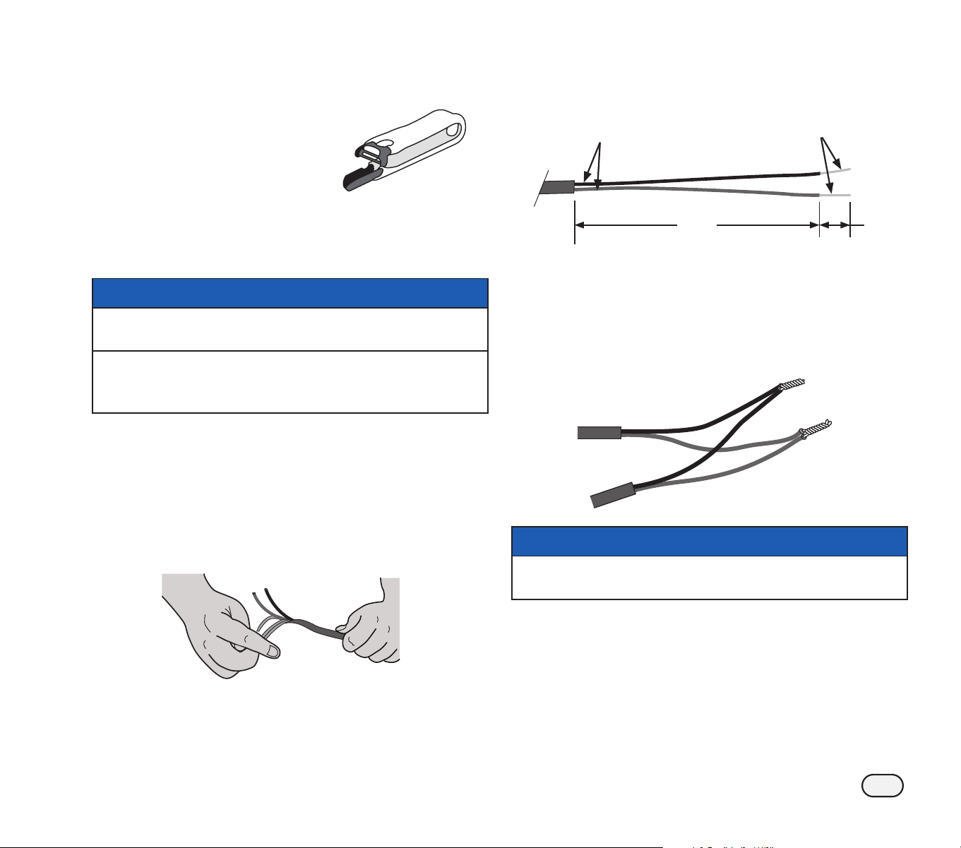
C
Remove the pre-cut insulation from the ends of the
wires on the 2-Wire device. Connect the device wires
to the 2-Wire path using linesman’s pliers to twist the
ends together.
C
NOTICE
Wire colors must be paired red to red and black to black in
order to maintain polarity when completing wire splices.
8
ESP-LXIVM Series Controllers
D
Insert the connected wires into the provided wire-nuts
and twist to secure.
E
Insert the wire-nut all the way into the WC20 connec-
tor. Position wires on side of the connector as shown
and then snap the cap shut.
D
E
Completed Wire Splice
Scan the QR code to see
a video on how to make
2-Wire cable connections.
Installation
2-Wire Address Labels
Before installing the 2-Wire Device, apply your 2-Wire
Device barcode labels to the appropriate fields on
the Programming Guide.
B
NOTE: See the ESP-LXIVM Programming Guide that
came with your controller.
A
Carefully peel off the station, master valve, flow or
weather sensor device barcode label.
B
Apply the 2-Wire Device address labels in the appropri-
ate fields on the Programming Guide.
B
NOTE: Do not remove the label from the carrier
attached to the wire.
40005
40005
40005
9
ESP-LXIVM Series Controllers
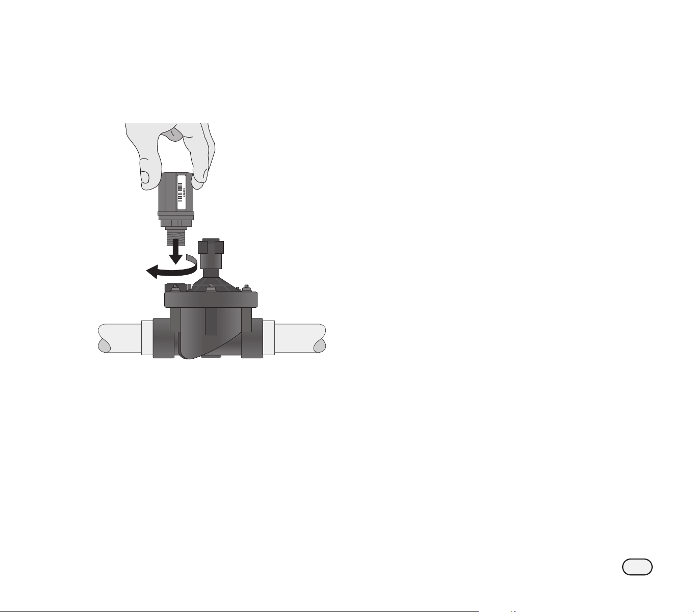
IVM-SOL Installation
A
Use pressure sprayer to clean equipment.
B
Check that O-rings are free from damage or debris.
C
Attach IVM-SOL hand-tight (with no water pressure).
B
NOTE: It’s normal to hear a brief ratcheting sound dur-
ing installation of the IVM-SOL on a valve.
10
ESP-LXIVM Series Controllers
Connect IVM-SOL to a Valve
A
Connect the red and black wires on the
IVM-SOL to the 2-Wire Path.
B
For future troubleshooting or modifica-
tions, it is recommended to leave an addi-
tional 3 feet (1 meter) of 2-Wire cable stored
in each valve box location.
B
NOTE: If the valve is NOT at the end of the
2-Wire Path then make a three-way splice;
the red wire from the valve module to the
two red wires of the 2-Wire Path; then splice
the valve module black wire to the two
black wires of the 2-Wire Path.
NOTICE
Use only WC20 splice kits for all wiring
connections to the 2-Wire Path. Improper
wiring can cause serious damage to your
controller or irrigation system.
Connect IVM-SOL to a Master Valve
Up to 5 master valves can be connected to the
2-Wire path of the ESP-LXIVM controller and up
to 10 master valves for the LX-IVM Pro controller.
IVM-SOL can be used for both station and master
valves. Master valves are connected using the
same processes as described previously.
B
NOTE: Be sure to attach the barcode labels
to the Programming Guide as a Master
Valve instead of a Station.
NOTICE
If retro-fitting, do not use TBOS (Battery Operated System)
solenoids or decoders in the ESP-LXIVM system.
Ensure that all decoders are disconnected from the 2-Wire path.
Valve
Box
IVM-SOL
2-Wire
Cable
Allow 3 ft. (1 m)
Extra Cable
Length
A
B
Typical IVM-SOL Valve Wiring
11
ESP-LXIVM Series Controllers
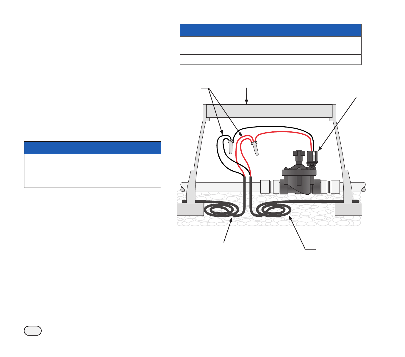
IVM-OUT (Output Device)
IVM-OUT 2-Wire control devices can be used
to control valves with DC latching solenoids.
A
Connect the red and black wires on the IVM-
OUT to the 2-Wire Path.
B
Connect the red/white striped wire on the
IVM-OUT to the DC latching solenoid red
wire.
Connect the black/white striped wire on the
IVM-OUT to the DC latching solenoid black
wire.
C
For future troubleshooting or modifications,
it is recommended to leave an additional 3
feet (1 meter) of 2-Wire cable stored in each
valve box location.
B
NOTE: Make sure that the DC latching sole-
noid is compatible with non Rain Bird valves.
Contact the valve manufacturer for more
information.
NOTICE
Maximum combined wire length between IVM-
OUT and its load (e.g. Solenoid) shall be 48 in.
This includes pre-installed IVM-OUT wire (24 in.)
and solenoid wires (22 in.).
Use only WC20 splice kits for all wiring
connections to the 2-Wire Path. Improper wiring
can cause serious damage to your controller or
irrigation system.
Non-Rain Bird
valve with DC
Latching Solenoid
Valve
Box
2-Wire
Cable
Allow 3 ft. (1 m)
Extra Cable
Length
A
C
IVM-OUT
B
Typical IVM-OUT Wiring
12
ESP-LXIVM Series Controllers
IVM-SEN (Sensor Device)
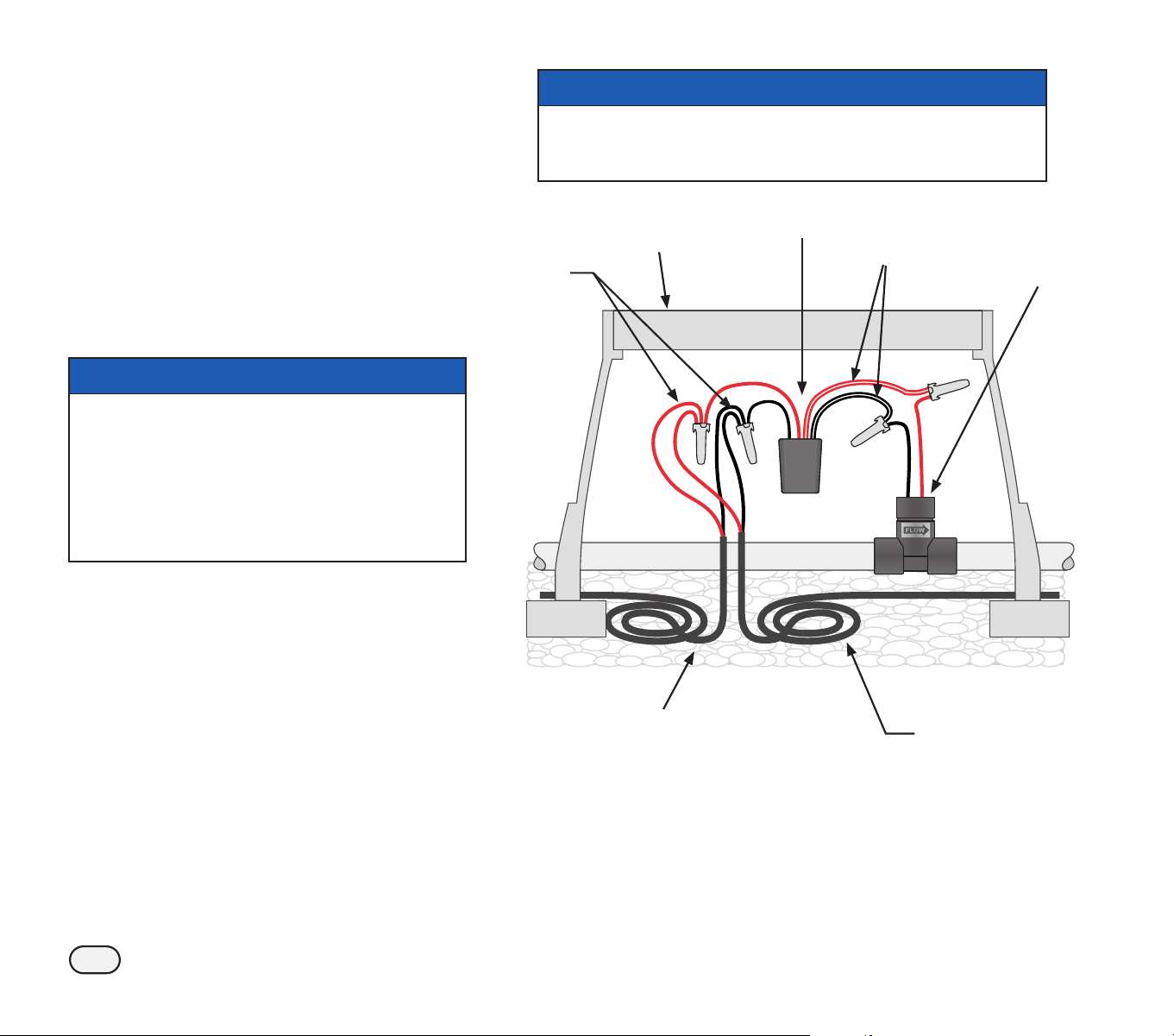
Flow sensors are connected to the 2-Wire
Path via IVM-SEN 2-Wire devices.
The ESP-LXIVM controller can support up to 5
flow sensors and the LX-IVM Pro controller can
support up to 10 flow sensors.
Connect Flow Sensors
A
Install flow sensors into your irrigation pip-
ing system at each point of connection to
the water supply (water meter or pump).
NOTICE
For optimum performance and flow sensing,
flow sensors should be installed a minimum of
10 pipe diameters in length on the upstream
(supply) side and a least 5 pipe diameters in
length on the downstream (delivery) side
before making any transitions in pipe size/
direction or away from the master valve.
B
Connect the red and black wires on the
IVM-SEN to the 2-Wire Path.
C
Connect the red/white striped wire on IVM-
SEN to the flow sensor red wire
Connect the black/white striped wire on
IVM-SEN to the flow sensor black wire.
B
NOTE: Be sure to follow all instructions
included with the flow sensor.
D
For future troubleshooting or modifica-
tions, it is recommended to leave an addi-
tional 3 feet (1 meter) of 2-Wire cable stored
in each valve box location.
NOTICE
Use only WC20 splice kits for all wiring connections to the
2-Wire Path. Improper wiring can cause serious damage to
your controller or irrigation system.
Valve
Box
FS-Series
Flow Sensor
2-Wire
Cable
Allow 3 ft. (1 m)
Extra Cable
Length
B
D
IVM-SEN
A
C
Typical IVM-SEN Flow Sensor Wiring
Connect Weather Sensors
In addition to flow sensors, the LX-IVM can also support three weather
sensors connected to the 2-Wire Path via an IVM-SEN. The LX-IVM Pro
controller supports seven 2-Wire Path weather sensors. Weather sen-
sors are connected to the LX-IVM Sensor input in the same way as the
flow sensor.
13
ESP-LXIVM Series Controllers
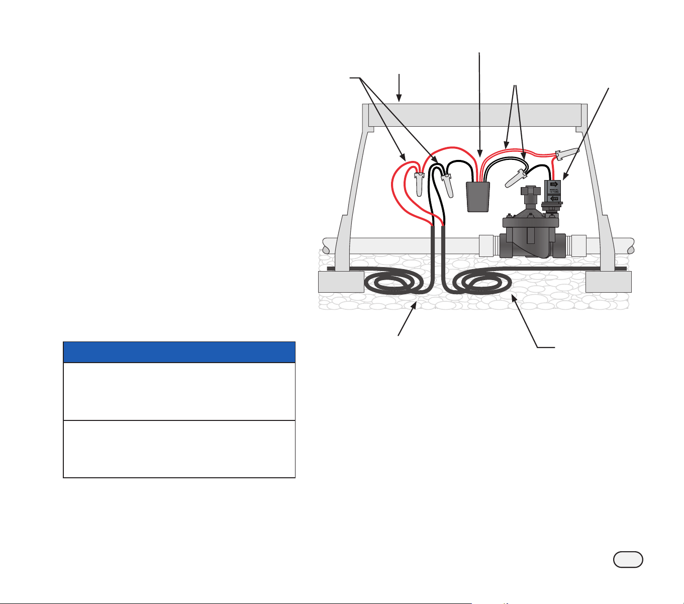
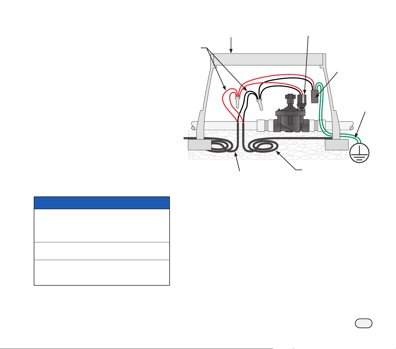
IVM-SD (Surge Device)
The IVM-SD provides surge protection for
the ESP-LXIVM controller and the 2-Wire
path.
The ESP-LXIVM controller and the 2-Wire path
must be properly surge protected and grounded.
Doing so can help prevent damage to the con-
troller and irrigation system and also significantly
reduce troubleshooting, repair time and expense.
Failure to do so could result in failure of your con-
troller and voiding the warranty.
A
Connect the red and black wires on the
IVM-SD to the 2-Wire Path
B
Connect the green wires from the IVM-SD
to the grounding rod or plate
C
For future troubleshooting or modifica-
tions, its is recommended to leave an addi-
tional 3 feet of 2-Wire cable stores in each
valve box location.
NOTICE
Use only WC20 splice kits for all wiring
connections to the 2-Wire Path. Improper wiring
can cause serious damage to your controller or
irrigation system.
One IVM-SD is required every 500 feet or every
15 field devices.
IVM-SD shall also be spliced into each 2-Wire
Path immediately next to the controller and at
the termination of each wire path.
IVM-SD
Valve
Box
2-Wire
Cable
Allow 3 ft. (1 m)
Extra Cable
Length
A
C
IVM-SOL
B
Typical IVM-SD Wiring
14
ESP-LXIVM Series Controllers
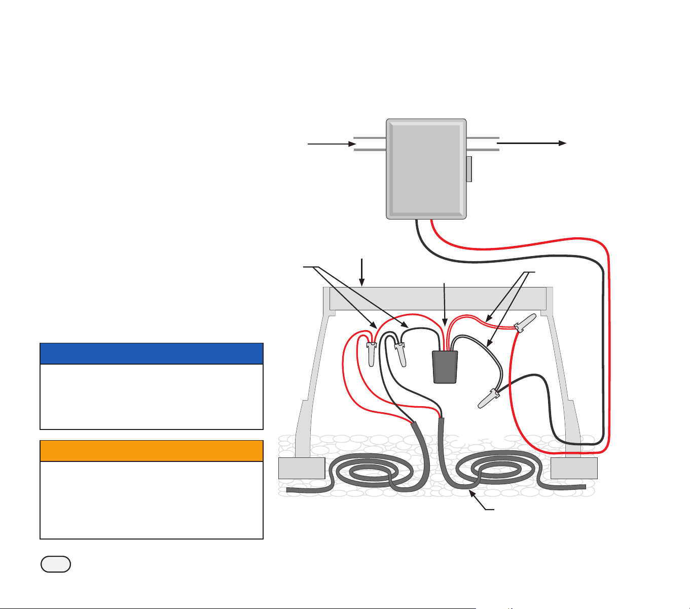
Pump Start Relay
IVM-OUT 2-Wire Control Devices can
control pump start relays that have a DC
latching input coil.
A
Connect the red IVM-OUT wire to the red
wire on the 2-Wire path. Then connect
the black IVM-OUT wire to the black wire
on the 2-Wire path.
B
Connect the red and white IVM-OUT wire
to the red wire of the DC Latching Relay.
Connect the black and white IVM-OUT wire
to the black wire of the DC Latching Relay.
C
Follow your Pump Start Relay wiring
instructions to connect input power and
pump.
D
For future troubleshooting or modifi-
cations, it is recommended to leave an
additional 3 feet (1 meter) of 2-Wire cable
stored in each valve box location.
NOTICE
Use only WC20 splice kits for all wiring
connections to the 2-Wire Path. Improper wiring
can cause serious damage to your controller or
irrigation system and work must be performed by
licensed electrician.
CWARNING
All electrical connections and wiring runs must
comply with local building codes. Some local
codes require that only a licensed or certified
electrician can install power. Only professional
personnel should install the controller. Check your
local building codes for guidance.
Pump Start with DC Latching Relay
Model Nos. PSR110-IVM and PSR220-IVM
Input
Power
Valve
Box
To Pump
Allow 3 ft. (1 m)
Extra Cable Length
A
D
IVM-OUT
C
B
Typical IVM-OUT Pump Start Relay Wiring
15
ESP-LXIVM Series Controllers
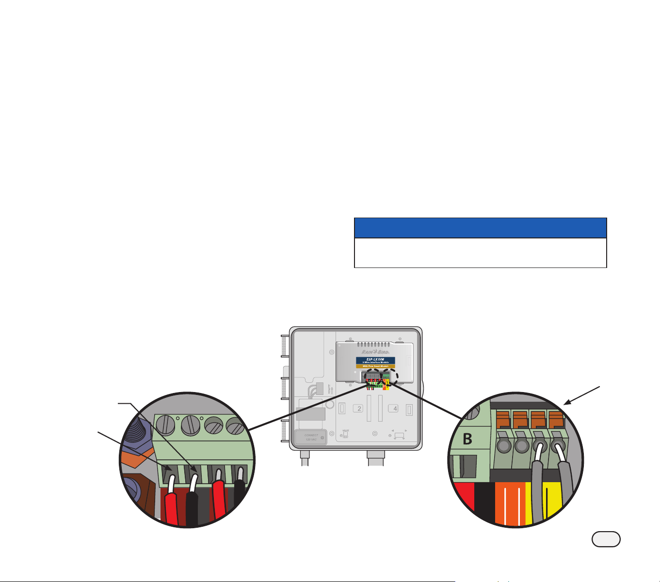
Connect 2-Wire (MAXI Cable) From
Field Devices
You can connect up to 4 pairs of 2 -Wires (MAXI
Cable) from the field devices back to the ESP-LXIVM
controller.
B
NOTE: Make sure the screws are all unscrewed all the
way out (while remaining in the module)
A
Connect the Red Wire from the MAXI Cable to the
Terminal with “R” marking
B
Connect the Black Wire from the MAXI Cable to the
Terminal with “B” marking
C
Tighten the screw
B
NOTE: The four pair of wires can be either in a Star pat-
tern or a Loop pattern. For details refer to the 2-Wire
Path overview section in the ESP-LXIVM user manual.
Connect Local Weather Sensors
ESP-LXIVM can also accept input from a single
weather sensor wired directly in to the controller.
B
NOTE: Follow the sensor manufacturer’s instructions
to correctly install and make wire connections to the
sensor.
D
Run continuous sensor wires from the weather sensor
to the ESP-LXIVM controller.
E
Remove the yellow jumper wire (if present). Connect
the sensor wires to the sensor (Sen) and common (C)
inputs.
NOTICE
Do not remove the yellow jumper wire unless
collecting a rain sensor.
B
NOTE: Ensure that the configuration for your control-
ler and irrigation programs are set up correctly for your
sensor.
R
B
R
B
B
A
E
J
”Rain Bird” and “Flo-Manager” are registered trademarks of Rain Bird Corp.
I
2020 Rain Bird Corporation P/N: 690715-01 Rev. 12/20
Rain Bird Corporation
6991 East Southpoint Road
Tucson, AZ 85756
USA
Tel: (520) 741-6100
Rain Bird Turkey
Çamlık Mh. Dinç Sokak Sk. No.4 D:59-60
34760 Ümraniye, İstanbul
TÜRKIYE
Tel: (90) 216 443 75 23
www.rainbird.com.tr
Rain Bird Ibérica S.A.
C/ Valentín Beato, 22 2ª Izq. fdo
28037 Madrid
ESPAÑA
Tel: (34) 91 632 48 10
[email protected] · www.rainbird.es
www.rainbird.pt
Rain Bird Corporation
970 W. Sierra Madre Ave.
Azusa, CA 91702
USA
Tel: (626) 812-3400
Rain Bird Europe SNC
Rain Bird France SNC
240 rue René Descartes
Bâtiment A, Parc Le Clamar
BP 40072
13792 AIX-EN-PROVENCE CEDEX 3
FRANCE
Tel: (33) 4 42 24 44 61
[email protected] · www.rainbird.eu
[email protected] · www.rainbird.fr
Rain Bird Australia Pty Ltd.
Unit 13, Level1
85 Mt Derrimut Road
PO Box 183
Deer Park, VIC 3023
Tel: 1800 724 624
[email protected].com.au
www.rainbird.com/au
Rain Bird International
1000 W. Sierra Madre Ave.
Azusa, CA 91702
USA
Tel: +1 (626) 963-9311
Rain Bird Deutschland GmbH
Königstraße 10c
70173 Stuttgart
DEUTSCHLAND
Tel: +49 (0) 711 222 54 158
Rain Bird Brasil Ltda.
Rua Marques Póvoa, 215
Bairro Osvaldo Rezende
Uberlândia, MG, Brasil
CEP 38.400-438
Tel: 55 (34) 3221-8210
www.rainbird.com.br
Technical Support
Questions?
Call Rain Bird toll free Technical Support
at 1-866-544-1406
(USA and Canada only)
Find the full ESP-LXIVM user manual
and trouble shooting information at
www.rainbird.com