LXME2
Series Controllers
Installation, Programming & Operation Guide
CAUTION:
This appliance is not intended for use by persons (including children) with
reduced physical, sensory or mental capabilities, or lack of experience and
knowledge, unless they have been given supervision or instruction concerning
use of the appliance by a person responsible for their safety.
Children should be supervised to ensure that they do not play with the
appliance.
For controllers not provided with supply cord, the xed installation must
include a disconnecting device for all three poles suitable for overvoltage
category III protection.
WARNING:
The LXME2 controller must be properly surge protected and grounded. Doing
so can help prevent damage to the controller and irrigation system and also
signicantly reduce troubleshooting, repair time and expense. Failure to do so
could result in failure of your controller and voiding the warranty.
Electric shock can cause severe injury or death. Make sure power supply is
turned OFF before connecting power wires.
All electrical connections and wiring runs must be made according to local
building codes.
The current date and time on the controller is retained by a long-life lithium
battery, which must be disposed of in accordance with local regulations.
This controller uses a non-replaceable lithium battery. Lithium batteries
are hazardous and can cause severe or fatal injuries in 2 hours or less if it is
swallowed or placed inside any part of the body. Medical attention should be
sought immediately if this is suspected. Keep batteries away from children
Current Section: Contents 2
Navigation:
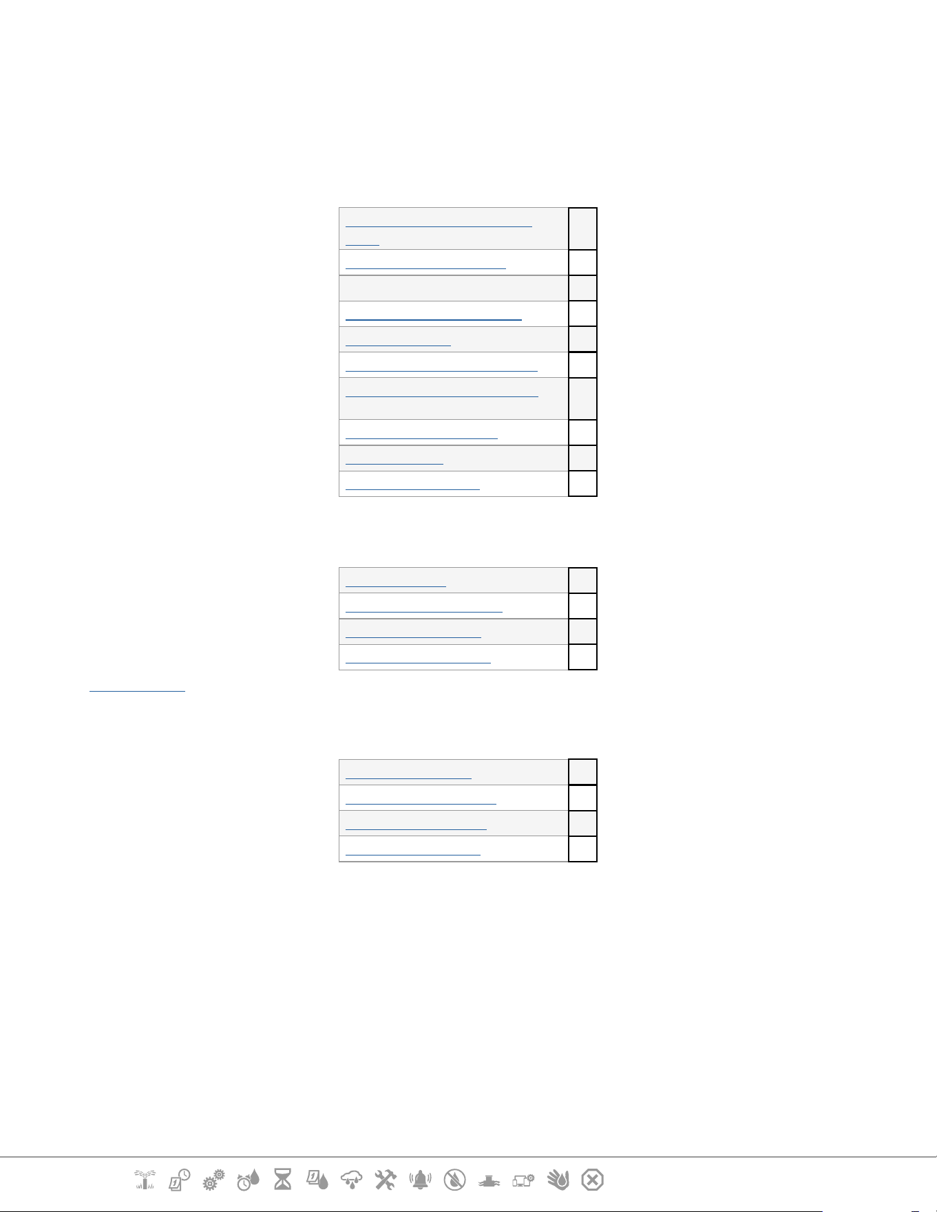
CONTENTS
1. INTRODUCTION .............................................................................................5
1.1 LXME2 Controller Overview .......................................................................................................5
1.2 Controller Features .....................................................................................................................5
1.3 In the Box ......................................................................................................................................6
1.4 Regulatory Compliance ..............................................................................................................6
1.5 Valves (Stations) .......................................................................................................................................... 7
1.6 Programming Overview .............................................................................................................7
1.6.1 Programs .............................................................................................................................................................7
1.6.2 Storing the Quick Start Guide ............................................................................................................................7
1.6.3 Remote Programming ........................................................................................................................................ 7
1.7 Interface Overview ......................................................................................................................8
1.8 Programming Checklist ..............................................................................................................9
1.8.1 Set Up Hardware .................................................................................................................................................9
1.8.2 Set Up Programs .................................................................................................................................................9
1.8.3 Set Up Advanced Programming (Optional) ...................................................................................................................9
1.8.4 Review Setup .....................................................................................................................................................10
1.8.5 Additional Advanced Programming (Optional) ........................................................................................................ 10
2. AUTO ....................................................................................................11
2.1 Alarms ....................................................................................................................................... 12
3. Set Date/Time ......................................................................................13
4.
Setup ....................................................................................................14
4.1 Master Valves ............................................................................................................................ 14
4.2 Weather Sensors ....................................................................................................................... 20
4.3 Station Setup ............................................................................................................................ 21
4.3.1 Station Priority ..................................................................................................................................................21
4.3.2 Master Valves/ Pumps ......................................................................................................................................22
4.3.3 Weather Sensors ...............................................................................................................................................22
4.3.4 Valves Per Station .............................................................................................................................................23
4.3.5 Flow Sensors - Models only .................................................................................................................................... 23
4.4 Advanced Station Settings ...................................................................................................... 27
4.4.1 Cycle + Soak (Advanced Station Settings) .................................................................................................................... 27
4.4.2 Copy Station To Station ....................................................................................................................................28
4.4.3 Station Delay (Advanced Station Settings) .................................................................................................................. 28
4.4.4 SimulStations (Advanced Station Settings) .................................................................................................................. 29
4.4.5 Station Sequencing (Advanced Station Settings) ....................................................................................................... 30
4.4.6 Module/ Station Numbering (Advanced Station Settings) ...................................................................................... 32
5. Set Start Times .....................................................................................33
6.
Run Times ...............................................................................................34
Current Section: Contents 3
Navigation:
6.4.1 Copy Run Times .................................................................................................................................................35
7. Water Days ...........................................................................................36
7.4.1 Custom, By Day of Week ..................................................................................................................................36
7.4.2 Cyclic Days .........................................................................................................................................................37
7.4.3 Even days, Odd days, Odd no 31st ..................................................................................................................38
8. Weather Sensors ..................................................................................39
9.
Diagnostics ...........................................................................................40
9.4.1 Test all Stations .................................................................................................................................................40
9.4.2 Raster Wiring Test .............................................................................................................................................40
9.4.3 Conrm Programming .....................................................................................................................................41
9.4.4 Program Summary ...........................................................................................................................................41
9.4.5 Review Programs ..............................................................................................................................................43
9.4.6 Program Run Times ..........................................................................................................................................45
9.4.7 Station Run Times .............................................................................................................................................46
9.4.8 Master Valve Status ..........................................................................................................................................47
9.4.9 Weather Sensor Status .....................................................................................................................................47
10. Alarms/ History ..................................................................................48
10.4.1 Flow History.....................................................................................................................................................48
10.4.2 Clear Flow History ..........................................................................................................................................48
10.4.3 Flow Alarms .....................................................................................................................................................49
11. Seasonal Adjust ...................................................................................51
11.4.1 Individual Program ........................................................................................................................................51
11.4.2 By Month..........................................................................................................................................................51
12. Delay Watering ...................................................................................54
12.4.1 Rain Delay .......................................................................................................................................................54
12.4.2 Calendar Day O ............................................................................................................................................54
12.4.3 Program Water Window ................................................................................................................................55
12.4.4 Water Window Set Up .....................................................................................................................................56
13. Flow Sensor ......................................................................................57
13.4.1 Introduction to Flow .......................................................................................................................................57
13.4.2 FloZones Overview .........................................................................................................................................57
13.4.3 Flow Management Features ..........................................................................................................................57
13.1 Flow Sensors ........................................................................................................................... 57
13.1.1 Selected Stations ............................................................................................................................................59
13.1.2 Set Station Rates .............................................................................................................................................61
13.1.3 Set FloZone Rates ...........................................................................................................................................62
13.1.4 View Flow Rates ..............................................................................................................................................62
13.1.5 View FloZone Rates ........................................................................................................................................64
13.1.6 Clear Flow Rates .............................................................................................................................................. 64
13.1.7 Set Flo-Manager® ............................................................................................................................................ 65
13.1.8 Flo-Manager® Set Up ......................................................................................................................................65
Current Section: Contents 4
Navigation:
13.1.9 Enable or Disable Flo-Manager® ................................................................................................................... 65
13.1.10 Set FloWatch™ ..............................................................................................................................................65
13.1.11 FloWatch™ Set Up ......................................................................................................................................... 66
13.1.12 FloWatch™ On/O ........................................................................................................................................67
13.1.13 Set Flow Limits ..............................................................................................................................................67
13.1.14 Set Up and Congure High Flow and Low Flow ........................................................................................68
13.1.15 Set Flow Actions ............................................................................................................................................69
13.1.16 Current Flow Reading ..................................................................................................................................69
13.1.17 Set Flow Units ................................................................................................................................................70
14. Advanced Settings ..........................................................................71
14.1.1 Store/ Recall Programs ................................................................................................................................... 71
14.1.2 Factory Defaults..............................................................................................................................................75
14.1.3 About this LXME2 ............................................................................................................................................ 76
15. Manual Watering ................................................................................ 77
15.1.1 Start Station ....................................................................................................................................................77
15.1.2 Start Program .................................................................................................................................................78
15.1.4 MV (Master Valve) Water Window ................................................................................................................78
15.1.5 Manual MV Open ............................................................................................................................................80
16. OFF ......................................................................................................81
16.1.1 Adjust Display Contrast .................................................................................................................................81
16.1.2 Close Master Valves ........................................................................................................................................81
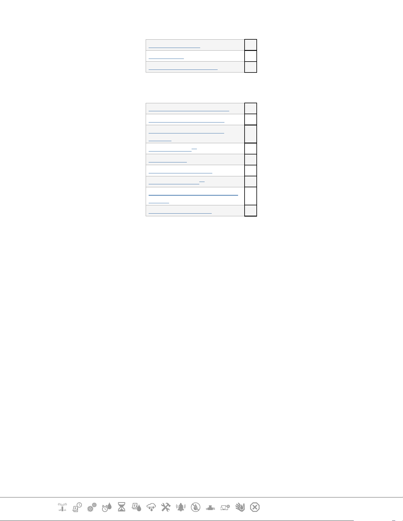
17. Installation ................................................................................................82
17.1 Install the Controller .............................................................................................................. 82
17.1.1 Installation Checklist ......................................................................................................................................82
17.1.2 Check Box Contents ........................................................................................................................................82
17.2 Select Location for Controller ............................................................................................... 83
17.2.1 Gather Installation Tools ..............................................................................................................................83
17.2.2 Access Controller Cabinet ..............................................................................................................................84
17.3 Mount the controller ............................................................................................................. 85
17.4 Connect source power ........................................................................................................... 85
17.4.1 Install base and station module (BCM or PSM) ........................................................................................................ 86
17.4.2 Install Station Module ...................................................................................................................................86
17.5 Dynamic Station Numbering ............................................................................................... 87
17.5.1 Connect Field Wiring ......................................................................................................................................88
17.5.2 Connect Local Weather Sensor .....................................................................................................................88
17.5.3 Connect a Flow Sensor -
Models Only .............................................................................................................. 89
17.5.4 Verify Field Installation .................................................................................................................................90

Current Section: INTRODUCTION 5
Navigation:
1. INTRODUCTION
Thank you for purchasing your new state-of-the-art Rain Bird LXME2 controller.
For eight decades Rain Bird has led the irrigation industry in meeting water management needs by
providing the highest quality products and services available.
1.1 LXME2 Controller Overview
Your new Rain Bird controller is designed to provide years of highly manageable irrigation control.
• The LXME2 controller is designed for commercial use.
• The LXME2 is congurable from 12 to 48 stations.
1.2 Controller Features
• Large LCD display with easy to navigate softkey user interface
• Hot-swappable modules, no need to power down the controller to add/remove modules
• Dynamic station numbering eliminates station numbering gaps
• Weather Sensor input with override switch
• Master valve/pump start circuit
• 6 user-selectable languages
• Non-Volatile (100- year) program memory
• Standard 10kV surge protection
• Front panel is removable and programmable under battery power
Models only
• Flow sensing capability (1 Flow Zone)
• Learn Flow - Automatically Learn Flow rates based on real-time usage
• Flow Watch - Compares expected vs. actual ow and takes user identied actions to diagnose,
shutdown, and alarm the system
• Flow Usage Totalizer
• MV2/P - Additional 2nd Normally closed master valve or booster pump start circuit programmable
by station

Current Section: INTRODUCTION 6
Navigation:
1.3 In the Box
• LXME2: controller, Base module, 12 station module
• Mounting hardware (5 screws, 5 plastic wall anchors)
• Controller cabinet keys
• Controller mounting template
• Quick Start (including Programming Guide)
• Station Numbering Labels
• Wire nuts
1.4 Regulatory Compliance
• 120VAC models UL, FCC, ISED.
• 230VAC models CE, UKCA, ACMA RCM.

Current Section: INTRODUCTION 7
Navigation:
1.5 Valves (Stations)
Valves, or stations are controlled and operate according to irrigation programs.
The controller is programmed to send signals to valves, which open and close on a timed schedule.
When a program is nished, the controller shuts o that valve and provides electrical signal for the
second valve to open and so on.
1.6 Programming Overview
1.6.1 Programs
The controller opens and closes valves according to a program you set. Each program contains:
Watering Start Times
The time(s) of day when the rst station is programmed to begin watering; all other stations in the
program then follow in sequence. See “Set Start Times” for more details.
Station Run Times
The length of time in hours and minutes that each individual station is programmed to run. See “Run
Times” for more details.
Watering Days
The days of the week or calendar dates on which irrigation is allowed. See “Water Days” for more
details.
Programming Guide
Before you begin programming, ll out the Programming Guide, this is located at the back of the
Quick Start Guide.
Enter information about your system hardware and settings in the appropriate elds on the
Programming Guide.
1.6.2 Storing the Quick Start Guide
Return the Quick Start Guide to a permanent, safe location when you’re nished working with it. We
recommend hanging it on the hook inside the controller cabinet door as shown below.
1.6.3 Remote Programming
The LXME2 controller can be programmed while operating under battery power.
Current Section: INTRODUCTION 8
Navigation:
This feature is useful if the controller is installed in an area that is not easily accessible. It also lets you
enter program information before installing the controller at the job site.
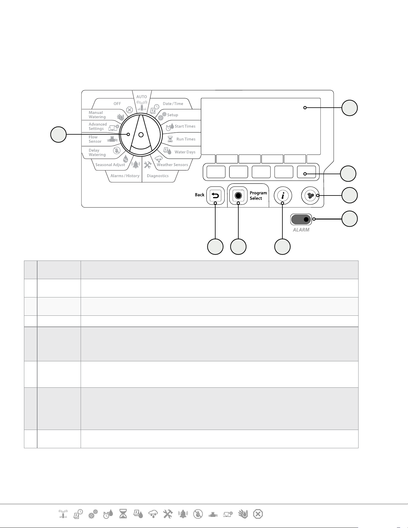
1.7 Interface Overview
Controls, Switches and Indicators of the LXME2 Controller:
e f
g
h
AU
TO
Mon 12:01
07 Mar 2021
a
b
d
c
a
Programming
Dial
Used to select irrigation features, programming and to turn the controller on and o .
b
Display
Displays time of day during normal operation; commands during programming, active station and
remaining run time during watering as well as other status messages and alarms.
c
Programming
Keys
Press buttons to navigate, enter and change program information. The function of each button is
labelled on the display above.
d
Back Button
The back button will take you back to the previous menu screen of the currently selected dial position.
e
Program
Select Button
Pressing the Program Select Button will show you the currently selected program and allow you to
select another using the programming buttons. Always begin programming by selecting the desired
Program (1-40). Multiple programs allow you to set watering schedules to meet dierent requirements
for plant materials, soils, slopes, and shady or sunny areas.
f
Information
Button
Pressing the Information Button In the Auto and Diagnostics dial positions will provide contact
information for Rain Bird Technical Support. In the other dial positions this button provides a
description of the currently selected dial position and menu screen.
g
Alarm Light
When an alarm condition is detected, the alarm light will illuminate. With the programming dial set to
‘Auto’, press the Alarm button (left most Programming Button) to view alarm details.
Any current alarm conditions will then be displayed on the display.
Take the appropriate action to address each alarm condition. When all alarms have been addressed,
the alarm light on the front panel will no longer be illuminated.
h
Language
Button
Press the Language Selection Button to change the interface language. Choose from English, Spanish,
French, German, Portuguese or Italian.
Current Section: INTRODUCTION 9
Navigation:
1.8 Programming Checklist
When programming the LXME2 controller for the rst time, it is recommended that you complete
the following steps in order.
1.8.1 Set Up Hardware
Install Base Module (BCM or
PSM)
Install Station module[s]
Fill out Programming Guide
Clear program information
Select language
Set the current date and time
Set up master valves/ pumps
(optional)
Set up weather sensors (optional)
Set up stations
Set up a ow sensor (optional)
1.8.2 Set Up Programs
Select program
Set watering start times
Select watering days *
Set station run time(s)
* See Watering Days dial position for Odd, Odd31, Even and Cyclical watering cycles.
1.8.3 Set Up Advanced Programming (Optional)
Set seasonal adjust
Create a water window
Set up a station delay
Set up Simulstations
Current Section: INTRODUCTION 10
Navigation:
1.8.4 Review Setup
Conrm programs
Test stations
Check installed modules
1.8.5 Additional Advanced Programming (Optional)
Check weather sensor status
Schedule calendar days o
Create a MV manual water
window
Set Cycle+Soak
TM
Set ow units
Activate Flo-Manager®
Activate FloWatch
TM
Set up High Flow and Low Flow
actions
Set controller to AUTO
Current Section: AUTO 11
Navigation:
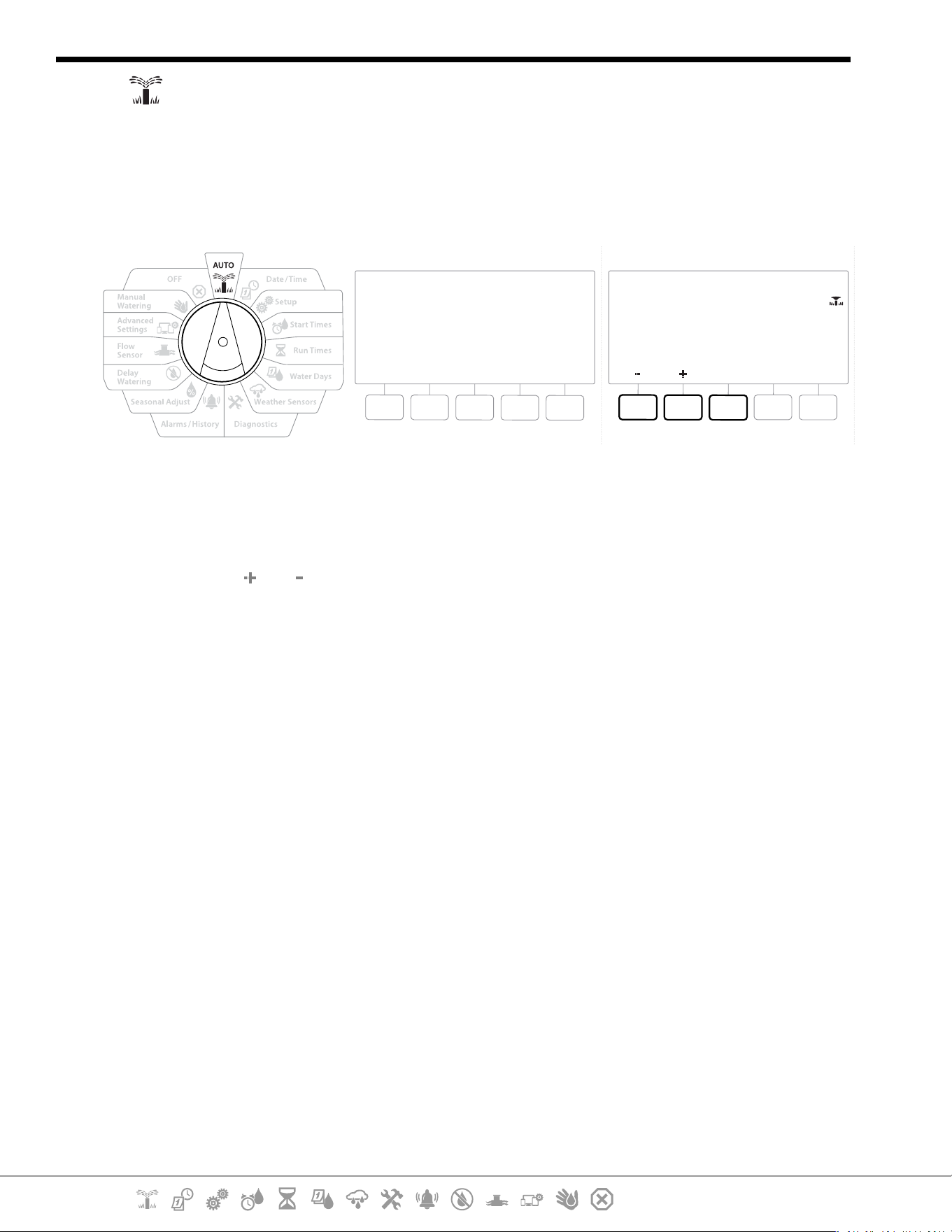
2. AUTO
AUTO is the normal operating mode. Programmed irrigation will run automatically with the
controller dial set to AUTO.
If you forget to return the dial to AUTO, the controller will automatically continue to run programs,
unless the dial is set to the OFF position when all irrigation is cancelled.
AUTO
Mon 12:01
07 Mar 2021
All Watering Off
12:01
Contrast 6
MV
Close
1 Turn the controller dial to AUTO
2 The Auto screen is displayed with the current day and time shown.
3 When a program is running in AUTO mode, the station number will show on the screen.
Press the and keys to add or subtract minutes from the run time for the currently
running station. To advance to the next station in a program, press the Adv key.
4 To cancel a currently running program, turn the controller dial to OFF for three seconds
and then return the dial to AUTO.
Current Section: AUTO 12
Navigation:
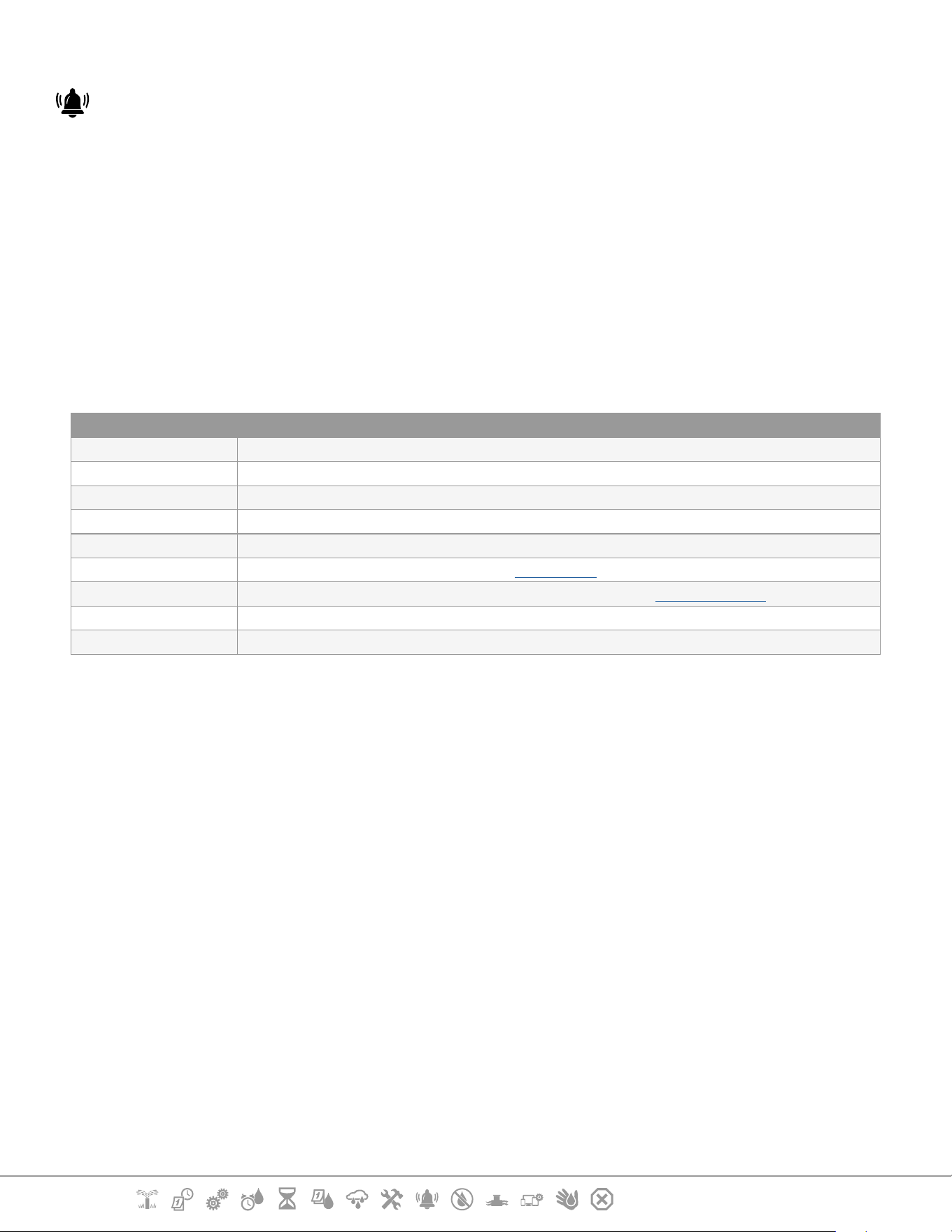
2.1 Alarms
An alarm condition can occur when programming omissions or other issues prevent normal
irrigation.
1 Turn the controller dial to AUTO
2 When an alarm condition is present, the Alarm key label will be present on screen. The
alarm indicator will also be lit red, this will be visible even with the lid closed. Press the
Alarm key to view alarm details.
3 Any present alarm conditions will then be shown. Press the More key to continue to the
next page
•
Take the appropriate action to address each alarm condition. When all alarms have been addressed, the
alarm light on the front panel will no longer be illuminated.
Alarm Condition
No Water Days There are no water days set in any program.
No Run Times There are no run times set in any program.
No Start Times There are no start times set in any program.
No PGM will AUTO Run There is no program with start times, run times and water days.
Max PGMs Stacked Max is 10 (equal to the start times).
Flow Alarm Shows for high or low ow conditions. See "Flow Alarms" for more details.
Zero Learned Flow 0 ow is learned for 1 or more stations FloWatch is turned on. See "Set Flo-Manager" for more details.
Invalid Module An incompatible module is installed in the cabinet.
No AC power The panel is running on the 9V battery (no AC).
Current Section: Set Date/Time 13
Navigation:
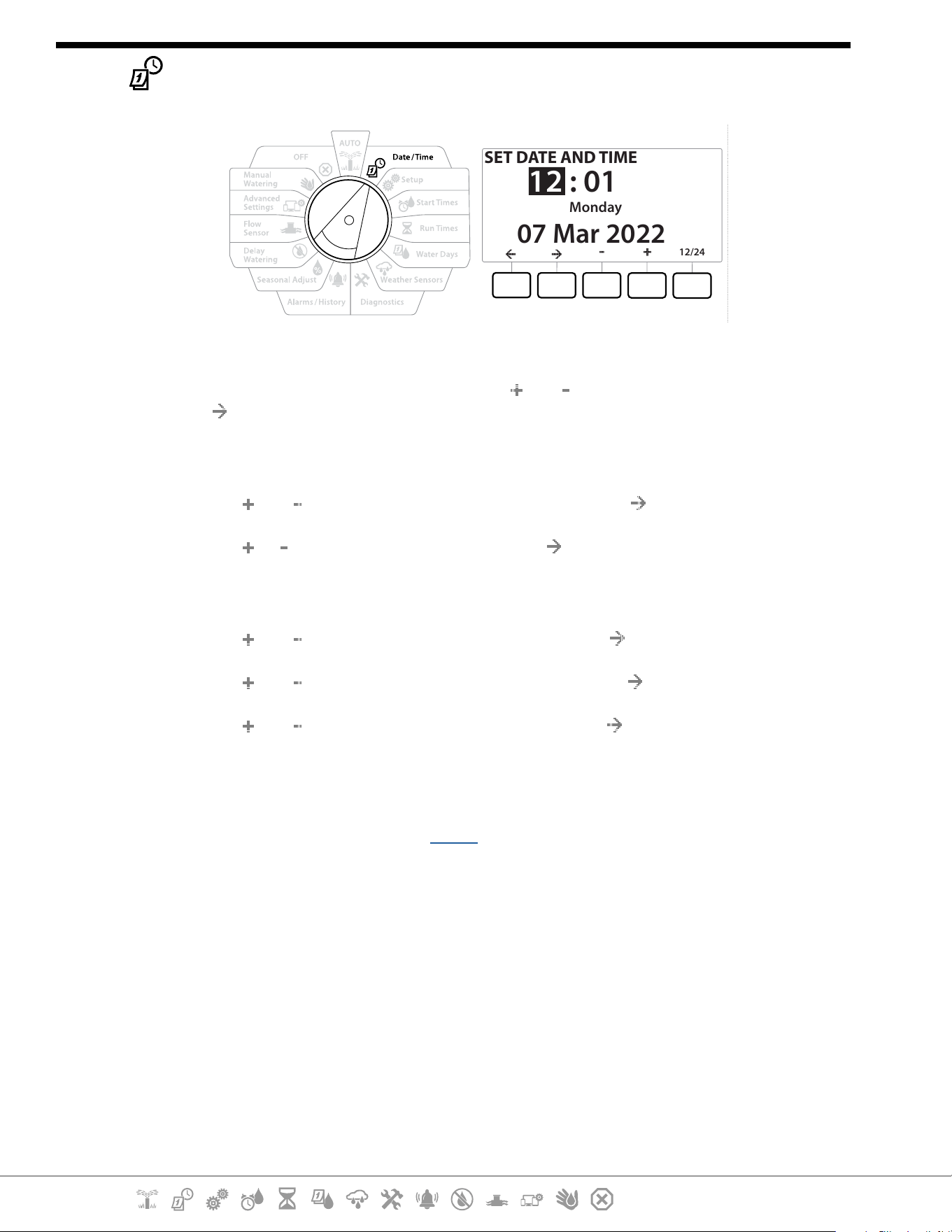
3. SET DATE/TIME
SET DATE AND TIME
: 01
07 Mar 2022
Monday
12
12/24
1 Turn the controller dial to Date/Time
2 At the SET DATE AND TIME screen, press the and keys to set the current hour, then
press
•
Press and HOLD keys to accelerate settings.
3 Press the and keys to set the current minute, then press
4 Press the or keys to set AM or PM, then press
•
The time will automatically updated once the current day, month and year entered.
5 Press the and keys to set the current date, then press
6 Press the and keys to set the current month, then press
7 Press the and keys to set the current year, then press
8 Press the 12/24 key to change the clock format from American standard to Military
standard
9 Proceed to the next dial position “Setup” to continue programming
•
The date will automatically updated once the current day, month and year entered.

Current Section: Setup 14
Navigation:
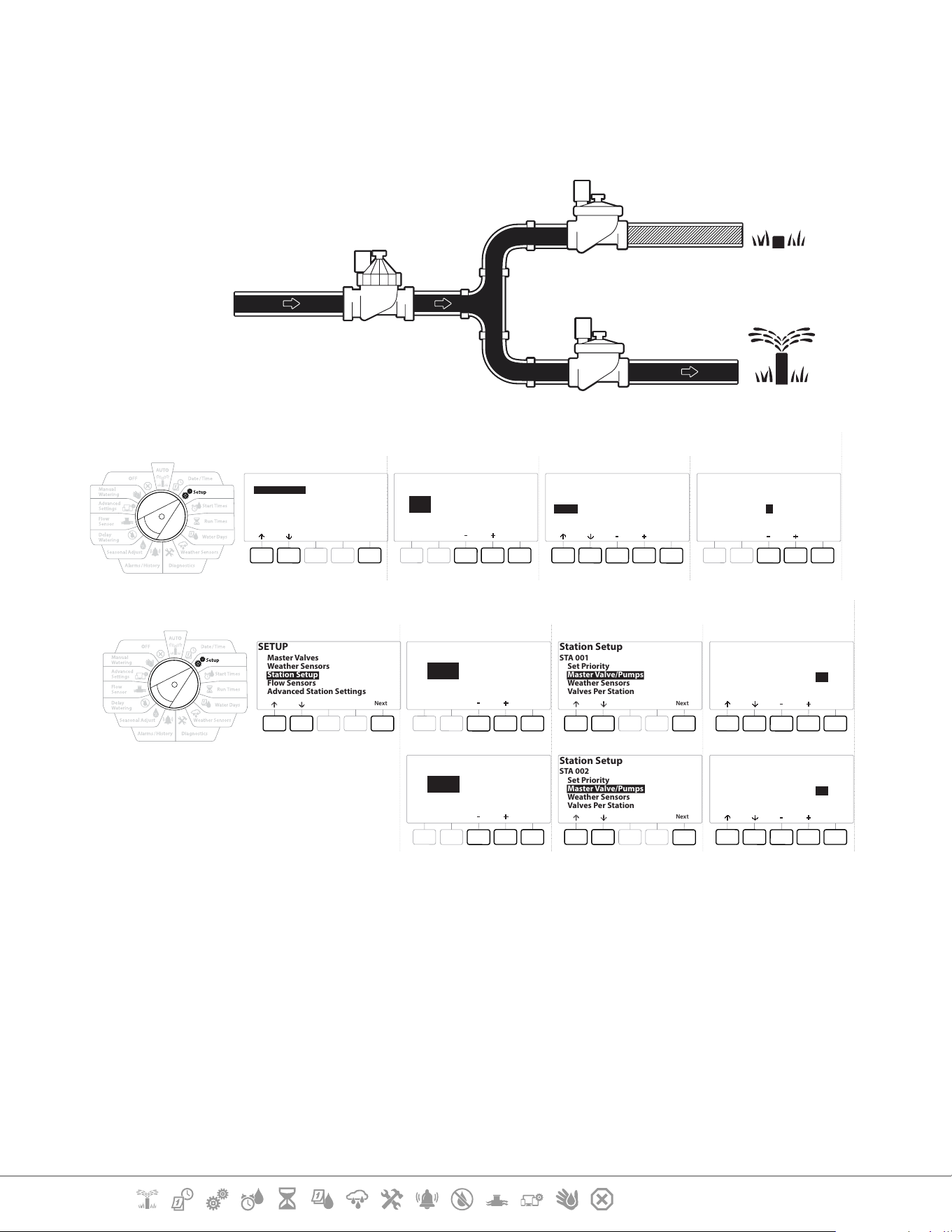
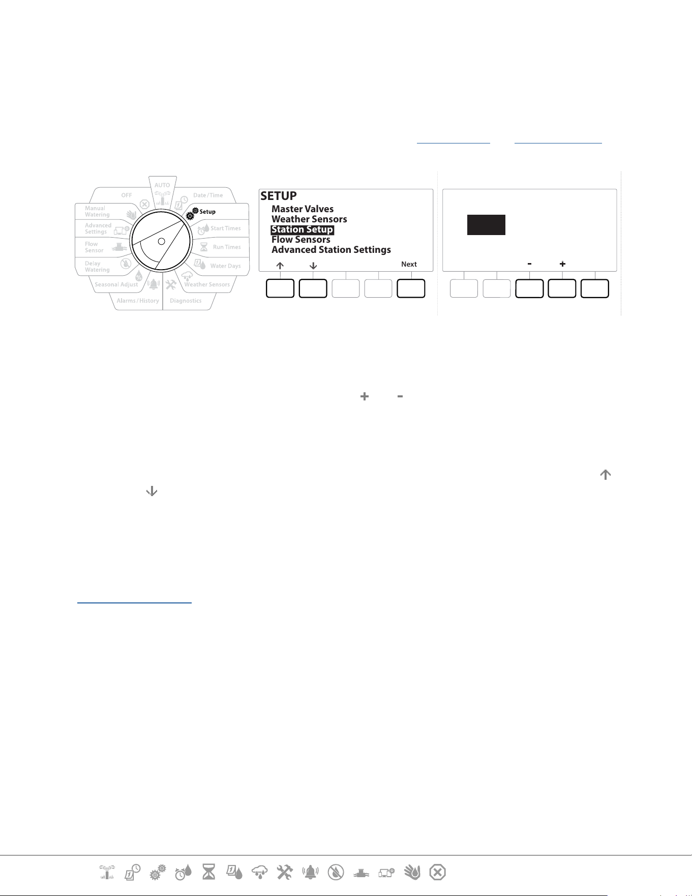
4. SETUP
The Setup dial position allows you to set up master valves, station valves, sensors as well as stations.
4.1 Master Valves
Master Valves Setup tells the LXME2 controller if a Master Valve (MV) or pump, or both is used by your
irrigation system.
The Master Valve can be congured either as a Normally Open Master Valve (NOMV) or as a Normally
Closed Master Valve (NCMV).
Models only
MV2/P can be congured only as a pump start or Normally Closed Master Valve (NCMV).
MV2/P can be turned on and o by station but always operates in conjunction with MV1.
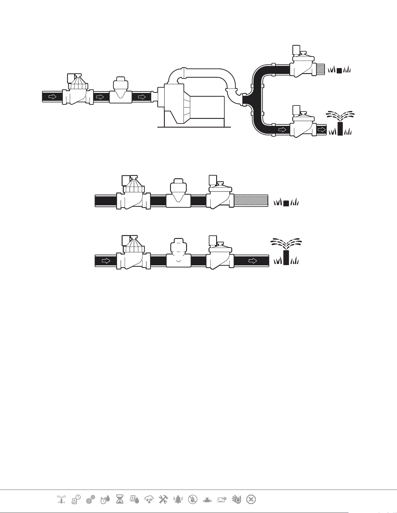
Current Section: Setup 15
Navigation:
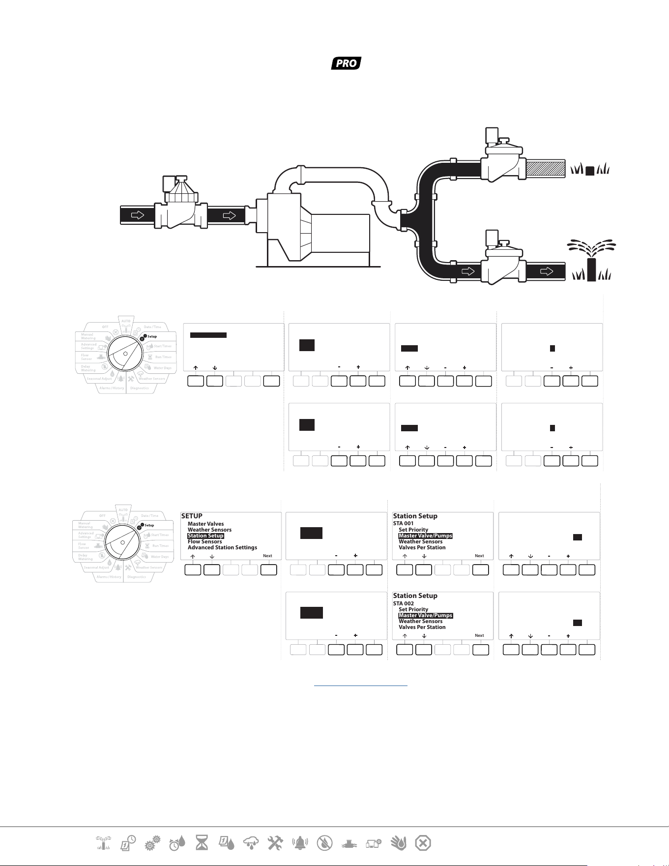
Conguration 1: Single NCMV Master Valve
STA 002 irrigating
STA 001
Closed
STA 002
Open
MV 01
NCMV or NOMV - Open
Water Source
(Point of
connection)
Master Valve Setup
SETUP
Next
Master Valves
Weather Sensors
Station Setup
Flow Sensors
Advanced Station Settings
Master Valve Setup
MV
Next
01
Done
MV 01
(only open when
stations operate)
Master Valve Setup
NCMV
Done
MV 01
Number of
Valves
Master Valve Setup
1
Station Setup
SETUP
Next
Master Valves
Weather Sensors
Station Setup
Flow Sensors
Advanced Station Settings
Station Setup
Next
STA
001
Station Setup
STA 001
Next
Set Priority
Master Valve/Pumps
Weather Sensors
Valves Per Station
Master Valve/ Pump Setup
Done
MV1
MV2
NCMV
Unused
Yes
----
STA 001
Station Setup
Next
STA
002
Station Setup
STA 002
Next
Set Priority
Master Valve/Pumps
Weather Sensors
Valves Per Station
Master Valve/ Pump Setup
Done
MV1
MV2
NCMV
Unused
Yes
----
STA 002
Current Section: Setup 16
Navigation:
Conguration 2: NCMV Master Valve & Pump -
Models only
STA 002 irrigating
Water Source
(Point of
connection)
STA 001
Closed
MV/P 02
Pump - On
MV 01
NCMV - Open
STA 002
Open
Master Valve Setup
SETUP
Next
Master Valves
Weather Sensors
Station Setup
Flow Sensors
Advanced Station Settings
Master Valve Setup
MV
Next
01
Done
MV 01
(only open when
stations operate)
Master Valve Setup
NCMV
Done
MV 01
Number of
Valves
Master Valve Setup
1
Master Valve Setup
MV/P
Next
02
Done
MV/P 02
(only on when
stations operate)
Master Valve Setup
Pump
Done
MV/P 02
Number of
Valves
Master Valve Setup
1
Station Setup
SETUP
Next
Master Valves
Weather Sensors
Station Setup
Flow Sensors
Advanced Station Settings
Station Setup
Next
STA
001
Station Setup
STA 001
Next
Set Priority
Master Valve/Pumps
Weather Sensors
Valves Per Station
Master Valve/ Pump Setup
Done
MV1
MV2
NCMV
Pump
Yes
No
STA 001
Station Setup
Next
STA
002
Station Setup
STA 002
Next
Set Priority
Master Valve/Pumps
Weather Sensors
Valves Per Station
Master Valve/ Pump Setup
Done
MV1
MV2
NCMV
Pump
Yes
Yes
STA 002
•
Refer to the following section for guidance on ow sensor setup.
Current Section: Setup 17
Navigation:
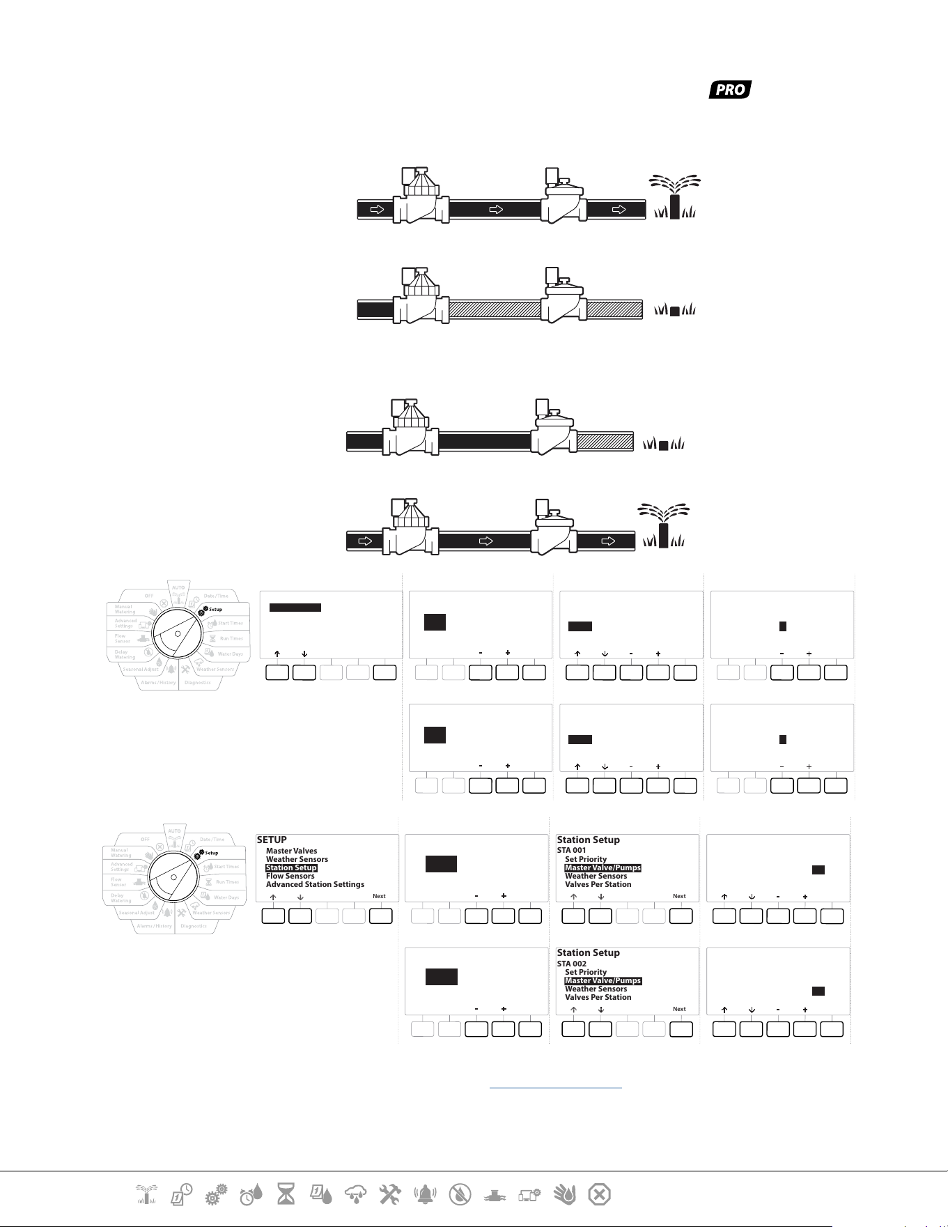
Conguration 3: Two Water Sources, MV1 & MV/P 02 Operating as NCMVs -
Models only
STA 001 irrigating
MV 01
NCMV - Open
STA 001
Open
STA 002
Closed
MV/P 02
NCMV - Closed
Water Source 1
(Point of
connection)
Water Source 2
(Point of
connection)
STA 002 irrigating
MV 01
NCMV - Open
STA 001
Closed
STA 002
Open
MV/P 02
NCMV - Open
Water Source 1
(Point of
connection)
Water Source 2
(Point of
connection)
SETUP
Next
Master Valves
Weather Sensors
Station Setup
Flow Sensors
Advanced Station Settings
Master Valve Setup
MV
Next
01
Done
MV 01
(only open when
stations operate)
Master Valve Setup
NCMV
Done
MV 01
Number of
Valves
Master Valve Setup
1
Master Valve Setup
MV/P
Next
02
Done
MV/P 02
(only on when
stations operate)
Master Valve Setup
Pump
Done
MV/P 02
Number of
Valves
Master Valve Setup
1
SETUP
Next
Master Valves
Weather Sensors
Station Setup
Flow Sensors
Advanced Station Settings
Station Setup
Next
STA
001
Station Setup
STA 001
Next
Set Priority
Master Valve/Pumps
Weather Sensors
Valves Per Station
Master Valve/ Pump Setup
Done
MV1
MV2
NCMV
Pump
Yes
No
STA 001
Station Setup
Next
STA
002
Station Setup
STA 002
Next
Set Priority
Master Valve/Pumps
Weather Sensors
Valves Per Station
Master Valve/ Pump Setup
Done
MV1
MV2
NCMV
Pump
Yes
Yes
STA 002
•
Refer to the following section for guidance on ow sensor setup.
Current Section: Setup 18
Navigation:
1 Turn the dial to Setup
2 At the SETUP screen, with “Master Valves” selected, press Next .
3 At the Master Valve Setup screen, press the and keys to select the desired Master
Valve press Next to make your selection.
•
MV/P 02 can only be used on models
SETUP
Next
Master Valves
Weather Sensors
Station Setup
Flow Sensors
Advanced Station Settings
Master Valve Setup
MV
Next
01
Master Valve Setup
MV/P
Next
02
MV01 - (NCMV or NOMV Setup)
1 Use the & buttons to choose between a normally open (NOMV) or normally closed
(NCMV) master valve to match your system conguration. Then press Next .
•
If your system does not have a master valve then select “Unused” and press Next.
2 Select the number of valves that the MV will control (1 or 2).
•
Setting the number of valves to 2 will not control the valves individually, it will only adjust the output voltage
to ensure both valves open.

Current Section: Setup 19
Navigation:
MV/P 02 - (Pump or NCMV Setup) -
Models Only
•
MV/P 02 will not function independently. To use it you must have MV 01 set up.
1 If your system includes a pump set MV/P 02 to “Pump” using the & buttons from the
Master Valves Setup screen, then press Next .
•
If your system does not have a master valve then select “Unused” and press Next.
2 Select the number of pumps/ master valves that the MV/P 02 will control (1 or 2).
•
Setting the number of pumps to 2 will not control them individually, it will only adjust the output voltage to
ensure both valves open.
•
MV02/P can also be used to set up a second Master valve (see Conguration 3)
Current Section: Setup 20
Navigation:
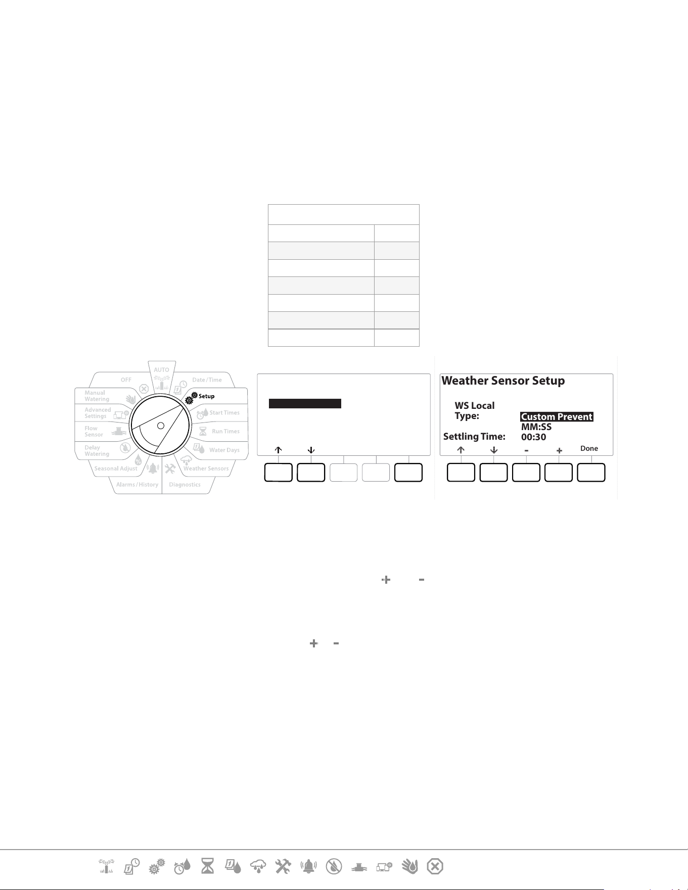
4.2 Weather Sensors
Weather Sensor Setup tells the LXME2 controller what types of weather sensors are used by your
irrigation system.
Weather sensors are not required for the LXME2 controller, but they increase functionality by
allowing irrigation control based on changing weather conditions. Follow the steps below if you
have a local weather sensor installed in your system.
The LXME2 supports 1 local weather sensor connected to the base module (BCM or PSM).
Sensor Types
Type Action
Rain Prevent
Freeze Pause
Wind Pause
Soil Moisture Prevent
Custom Pause Pause
Custom Prevent Prevent
SETUP
Next
Master Valves
Weather Sensors
Station Setup
Flow Sensors
Advanced Station Settings
Weather Sensor Setup
Done
WS Local
Type:
Settling Time:
Custom Prevent
MM:SS
00:30
1 Turn the controller dial to Setup
2 At the SETUP screen, with “Weather Sensors” selected, press Next .
3 At the Weather Sensor Setup screen, press the and keys to set the desired Sensor
type.
4 Press the button to set the settling time. This defaults to 00:30 seconds but a custom
settling time can be set using the & buttons.
•
Settling time is how long a weather condition must last before the controller takes action. For example, if a
freeze sensor has a 5 minute settling time then the temperature would have to remain below the sensor’s
threshold set point for 5 minutes before irrigation is paused. Settling time can be set for immediate (0
seconds) or up to 10 minutes long.
5 When you have set up your weather sensor press the Done key.
Current Section: Setup 21
Navigation:
4.3 Station Setup
Station Setup tells the LXME2 controller how many and what type of stations are used by your
irrigation system.
•
Before setting up stations, follow the previous instructions to set up master valves and weather sensors (if
present).
SETUP
Next
Master Valves
Weather Sensors
Station Setup
Flow Sensors
Advanced Station Settings
Station Setup
Next
STA
001
1 Turn the dial to Setup
2 At the SETUP screen, with “Station Setup” selected, press Next .
3 At the rst Station Setup screen, press the
and keys to set the Station you wish to
setup 1-12 (up to 48 if expansion modules are installed).
4 With the desired station selected press Next .
5 The station you are setting up will be displayed at the top of the next screen. Use the
and
buttons to navigate the menu.
4.3.1 Station Priority
Station Priorities are only used when Station Sequencing is set to Sequence by Station Priority. If you
are using the default Sequence by Station Numbers, then skip the next step by pressing “Next” (see
“Station Sequencing” for more information).
Current Section: Setup 22
Navigation:
Station Setup
STA 001
Next
Set Priority
Master Valve/Pumps
Weather Sensors
Valves Per Station
Station Setup
Done
Priority: High
STA 001
1 Select “Set Priority” and press the Next button.
2 Press the and keys to select the priority type. Each station can be set to High,
Medium, Low or Non-irrigation (Non-Irrig).
•
Non-irrigation stations such as fountains and landscape lighting receive priority to always run, regardless of
weather conditions.
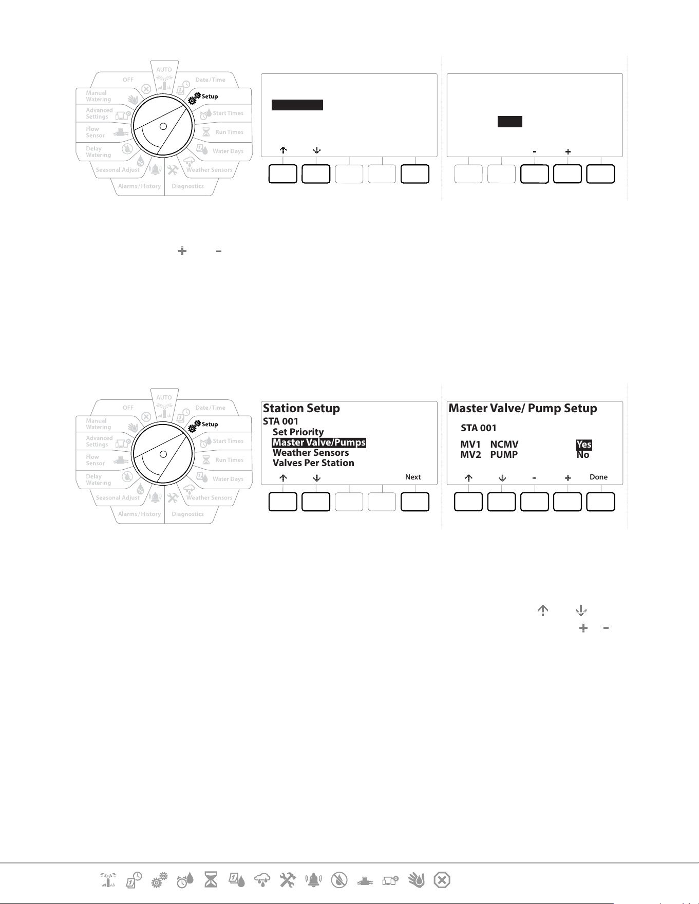
4.3.2 Master Valves/ Pumps
Station Setup
STA 001
Next
Set Priority
Master Valve/Pumps
Weather Sensors
Valves Per Station
Master Valve/ Pump Setup
Done
MV1
MV2
NCMV
PUMP
Yes
No
STA 001
1 On the Second Station Setup screen navigate to Master Valves/ Pumps then press the
Next button.
2 The Station you are setting up will be displayed at the top of the display. Use this screen
to tell the controller if the Station is connected to a master valve. Use the and
buttons to navigate between the MV1 (master valve) and MV2/P (pump). Press the &
buttons to select Yes (connected to MV) or No (not connected to MV).
3 Press the Done key to continue setting up the Station.
4.3.3 Weather Sensors
If you have a weather sensor connected to your system then follow the steps below to set it up in
the controller.
Current Section: Setup 23
Navigation:
SETUP
Next
Master Valves
Weather Sensors
Station Setup
Flow Sensors
Advanced Station Settings
DoneNoYes
Local
N
STA 001
Station Setup
Assign Weather Sensors
1 Navigate to Weather Sensors on the Station Setup screen and press Next.
2 Use the Yes and No buttons to choose weather the current station should obey or ignore
weather sensor input.
3 With Yes Selected the currently station will obey the connected Weather Sensor. For
example if a Rain sensor is connected then the if the Rain Sensor detects Rain irrigation
will be prevented for the Station.
4 With No selected the current station will ignore the state of a connected weather sensor.
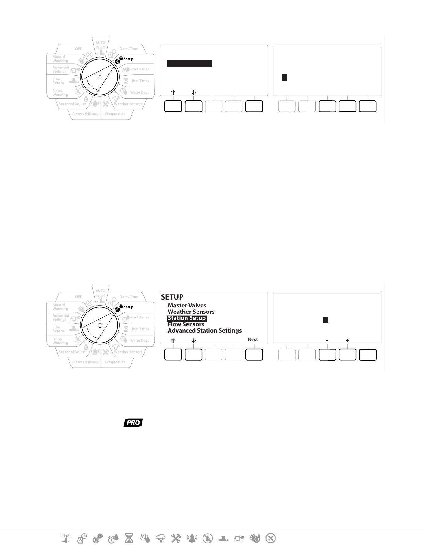
4.3.4 Valves Per Station
1 On the Second Station Setup screen navigate to Valves Per Station and press Next .
SETUP
Next
Master Valves
Weather Sensors
Station Setup
Flow Sensors
Advanced Station Settings
Done
Number of
Valves
STA 001
Station Setup
2
•
Setting the number of valves to 2 will not control them individually, it will only adjust the output voltage to
ensure both valves open.
4.3.5 Flow Sensors - Models only
A ow sensor is not required for the LXME2 controller, but it does add functionality by alerting you of
unexpected ow rates and even shutting down aected master valves or stations if ow rates exceed
set thresholds.
Current Section: Setup 24
Navigation:
Single Flow Sensor Installation Example
Dual Flow Sensor Installation Example
Flow Sensor 1
Flow Sensor 2 (Optional, see note below)
•
To measure ow from 2 water sources a device that scales the signals from two ow sensors and combines
them into one digital output is needed. Use Combiow CBF-100-00 or equivalent.
Current Section: Setup 25
Navigation:
Setup a Rain Bird Flow Sensor
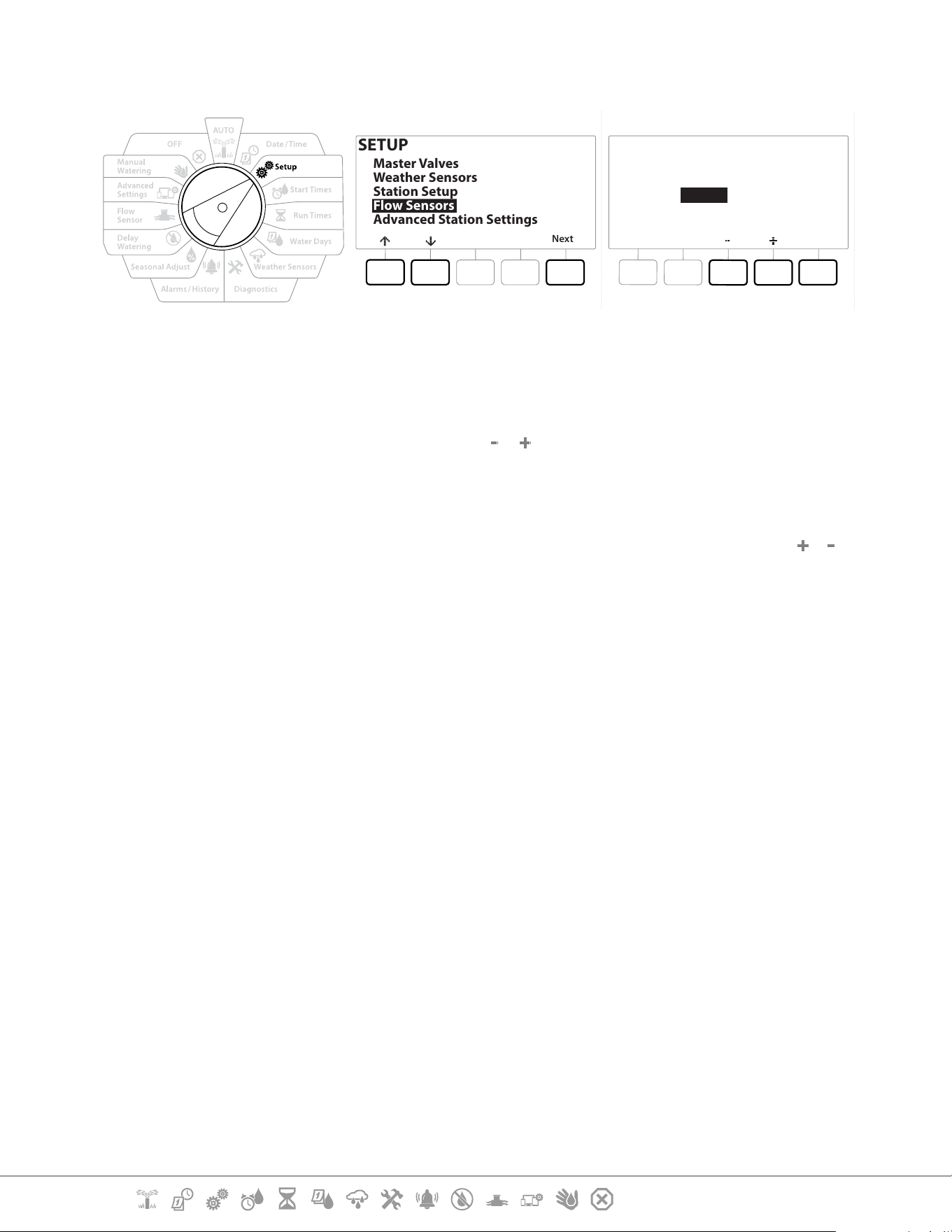
SETUP
Next
Master Valves
Weather Sensors
Station Setup
Flow Sensors
Advanced Station Settings
Next
Type:
FS 01
Flow Sensor Setup
FS100P
1 Turn the controller dial to Setup
2 On the SETUP screen, navigate to “Flow Sensors” using the up and down arrows, then
press Next .
3 On the Flow Sensor Setup screen use the & buttons to select the ow sensor model
that you are using, then press Next .
•
If you are using a ow sensor that is not listed then select “Custom”
•
The FS350B and FS350SS ow sensor types require the inside pipe diameter to be congured. Use the &
buttons to set this and then the “Next” button to nish.
Current Section: Setup 26
Navigation:
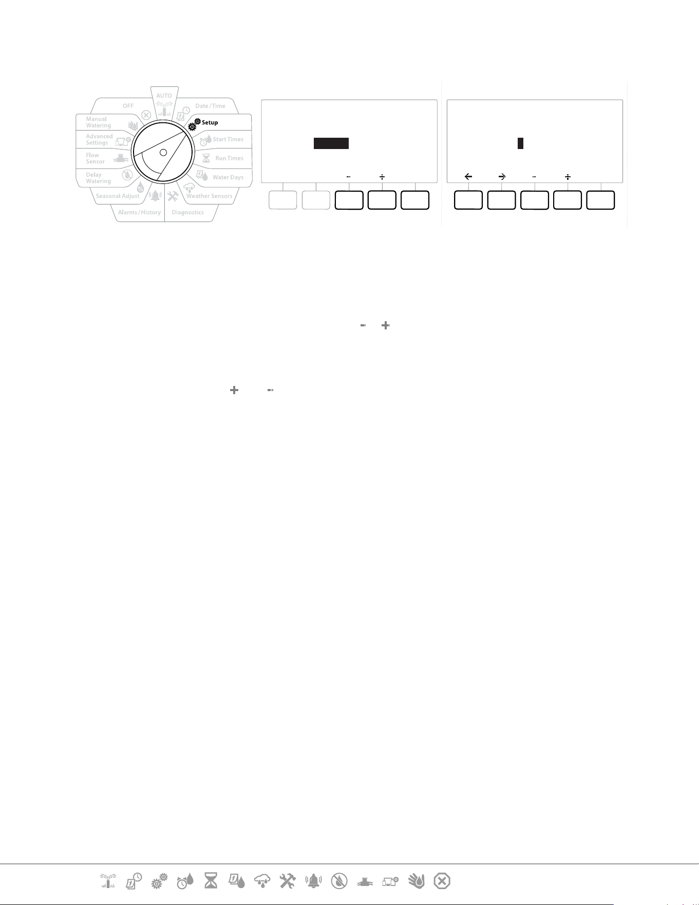
Setup a Third Party Flow Sensor (Custom)
Next
Type:
FS 01
Flow Sensor Setup
Custom
Next
K Factor:
Offset:
FS 01
Flow Sensor Setup
001.000
+00.000
1 Turn the controller dial to Setup
2 On the SETUP screen, navigate to “Flow Sensors” using the up and down arrows, then
press Next .
3 On the Flow Sensor Setup screen use the & buttons to navigate to “Custom”, then
press Next .
4 Use the arrow buttons to navigate between number settings elds of the K Factor and
Oset and use the and buttons to set the correct value.
•
Please refer to the instructions provided by the manufacturer of your ow sensor for the correct K Factor and
Oset. These numbers must be correct in order to provide accurate ow information.
5 Press Next when the values on screen are set to the correct value.
Current Section: Setup 27
Navigation:
4.4 Advanced Station Settings
4.4.1 Cycle + Soak (Advanced Station Settings)
The LXME2 controller Cycle+Soak feature allows water to be applied to stations intermittently.
This can apply to any station and is useful for locations such as hillsides which can be dicult to
irrigate eectively.
Cycle+Soak consists of two settings:
Cycle time: How long a station will run before soaking.
Soak time: How long irrigation is paused before applying another cycle.
For example, a station can be set up to receive 15 minutes of irrigation in three 5 minute cycles, with
two 10 minutes periods of soak time in between waterings.
•
Cycle+Soak™ settings apply to stations no matter which programs they may be used in.
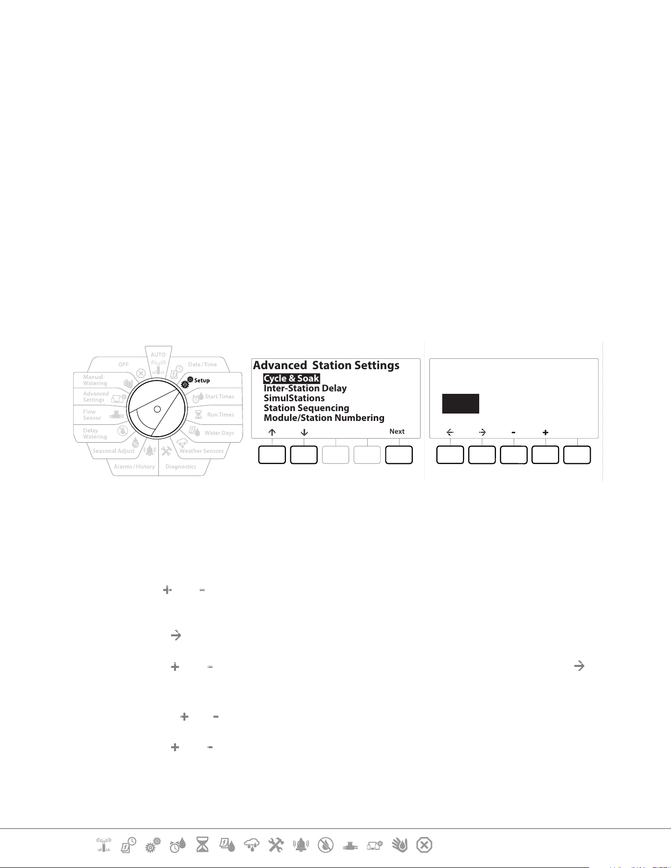
Next
Advanced Station Settings
Cycle & Soak
Inter-Station Delay
SimulStations
Station Sequencing
Module/Station Numbering
Copy
Station Cycle Soak
Minutes
Cycle & Soak
001 :00 :00
1 Turn the controller dial to Setup
2 On the Setup screen to navigate to “Advanced Station Settings”, then press Next .
3 With “Cycle & Soak” selected press Next .
4 Use the
and buttons to set the Station that you wish to apply Cylce + Soak
programming to.
5 Press the button to navigate to Cycle time.
6 Press the
and keys to set the Cycle time (between 1-60 minutes), then press the
button.
•
Press and HOLD the and buttons to accelerate minute settings.
7 Press the and keys to set the Soak time (between 1-60 minutes).
8 To cancel Cycle+Soak on a station, set both Cycle and Soak to 0.
Current Section: Setup 28
Navigation:
•
Consider using short Soak times, particularly if your watering schedule or Water Window is short. Long delay
times could prevent scheduled irrigation from completing prior to the end of the Water Window.
•
The controller is designed to allow additional stations in the irrigation queue to run during the soak time for
Cycle+Soak stations.
Repeat this process to set up Cycle+Soak on other stations, or copy this same programming to other stations
by following the steps below.
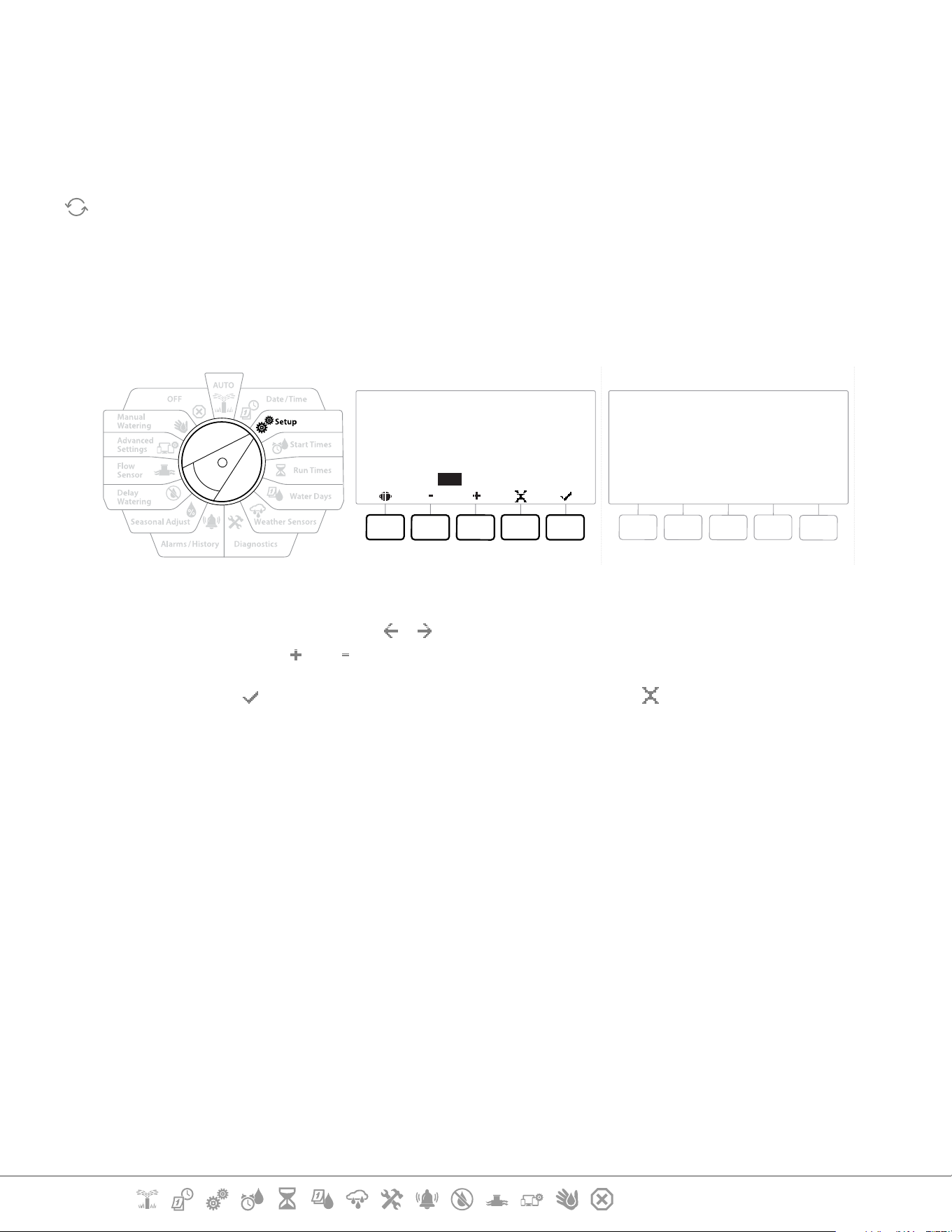
4.4.2 Copy Station To Station
Use this time saving feature to copy the Cycle+Soak™ Programming from one station to other
stations.
Cycle
10
Mins
Soak
05
Mins
001 003
to all stations between
Copy
Cycle
10
Mins
Soak
05
Mins
Sta. 001 through Sta. 003
Copied
1 At the Cycle+Soak™ screen, press the “Copy” key.
2 At the Copy screen, use the & buttons to navigate between the number setting
elds. Press the and keys to set the desired starting and ending station numbers.
3 Press the key to copy the Cycle+Soak settings, or press the key to cancel copying.
4 A conrmation screen shows the process is complete.
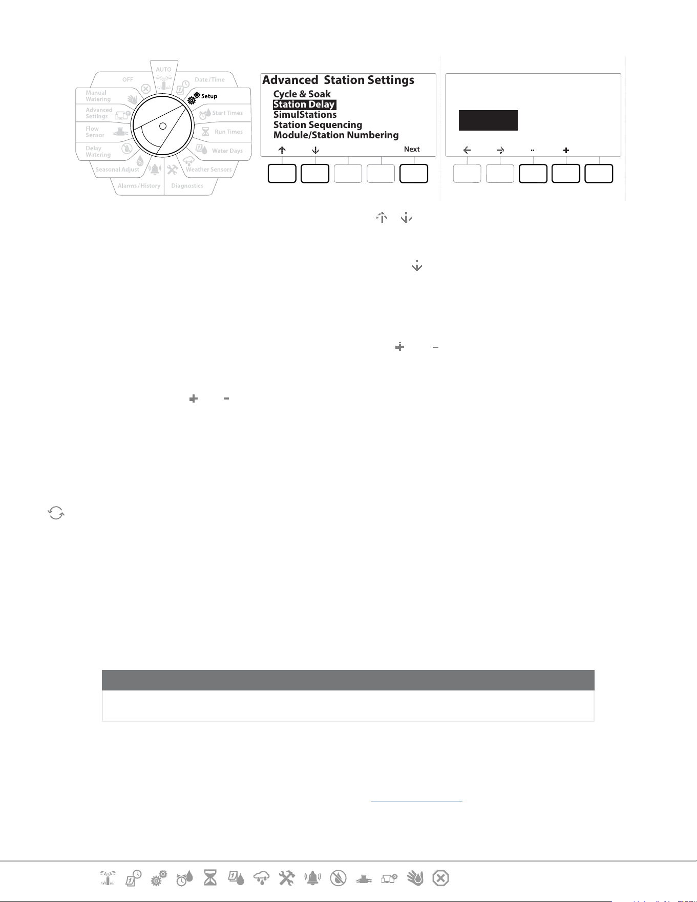
4.4.3 Station Delay (Advanced Station Settings)
The LXME2 controller can be programmed to include a delay between stations.
For example, if you set a one minute delay, Station 1 will run until nished, followed by a one minute
delay. Then station 2 will run, followed by another one minute delay, and so on.
Current Section: Setup 29
Navigation:
Next
Advanced Station Settings
Cycle & Soak
Station Delay
SimulStations
Station Sequencing
Module/Station Numbering
Done
Station
Min : Sec
00:00
Delay Between Stations
PGM 02
1 Turn the controller dial to Setup and use the & keys to navigate to “Advanced
Station Settings”
2 At the Advanced Station Settings screen, press the
key to select “Station Delay”, then
press Next .
3 At the Station Delay screen with “Inter Station Delay” selected press Next.
4 At the Delay Between Stations screen, press the and keys to set the time delay (from
00:01 second to 60:00 minutes).
•
Press and HOLD the and keys to accelerate settings.
•
To clear an Inter-station Delay on that station, set to 00:00
•
Consider using short Inter-station Delay times, particularly if your watering schedule or Water Window is
short. Long delay times could prevent scheduled irrigation from completing prior to the end of the Water
Window.
Use the Program Select button and repeat this process to set Inter-station Delay for other programs as
desired.
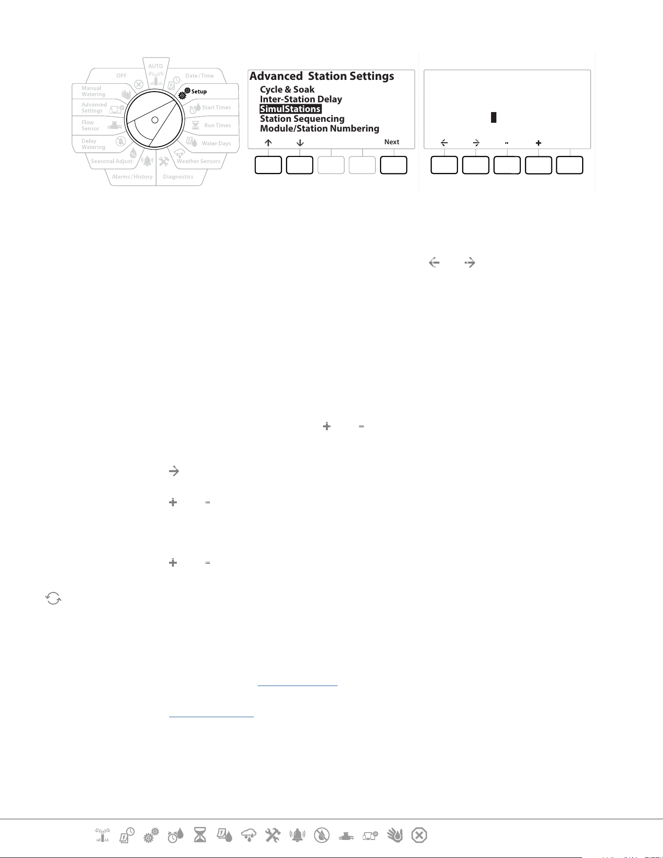
4.4.4 SimulStations (Advanced Station Settings)
The LXME2 controller can be set to operate multiple stations simultaneously.
You can set the maximum number of stations that are allowed to run concurrently as well as the
maximum number of stations an individual program can run. This can be benecial for systems with
a large water source and to help ensure watering is completed in the water window.
CAUTION:
The LXME2 can run a maximum of 5 stations concurrently, (limited to 2 stations per 12 Station module).
Many irrigation systems do not have sucient hydraulic capacity to accommodate such a load.
•
SimulStations can be used to control the maximum number of simultaneously irrigating stations per
program or for the entire controller. But a better alternative would be to enable Flo-Manager® and set
program-level SimulStations to a fairly high number. This will allow Flo-Manager® to provide maximum
irrigation based on your system’s hydraulic capacity. See “Set Flo-Manager®” for more details.
Current Section: Setup 30
Navigation:
Next
Advanced Station Settings
Cycle & Soak
Inter-Station Delay
SimulStations
Station Sequencing
Module/Station Numbering
Done
Type
Irrigation
Non-Irrig
SimulStations
PGM01
Global
5
1
PGM5
1
1 Turn the controller dial to Setup
2 At the Advanced Station Settings screen, navigate to SimulStations, then press Next .
There are two types of the SimulStations (Global and PGM). Press the
and to navigate between
the number setting elds.
Global - Maximum number (1-5) of simultaneously irrigating irrigation stations across all
programs.
PGM - Maximum number (1-5) of simultaneously irrigating irrigation stations for the currently
selected program, shown at the top of the screen.
Non-Irrig - Stations can be setup as non-irrigating (to control lighting for instance).
3 At the SimulStations screen, press the and buttons to set the number of Global
Irrigation stations (from 1 - 5).
4 Press the key to continue to the Program (PGM) Irrigation stations.
5 Press the and keys to set the desired number (from 1 - 5).
6 Press the Right Arrow key again to continue to the Non-irrigation (Non-Irrig) stations.
7 Press the and keys to set the desired number (from 1 - 5).
Use the Program Select button to change the program and repeat this process to set the Maximum Number
of Stations for other programs as desired.
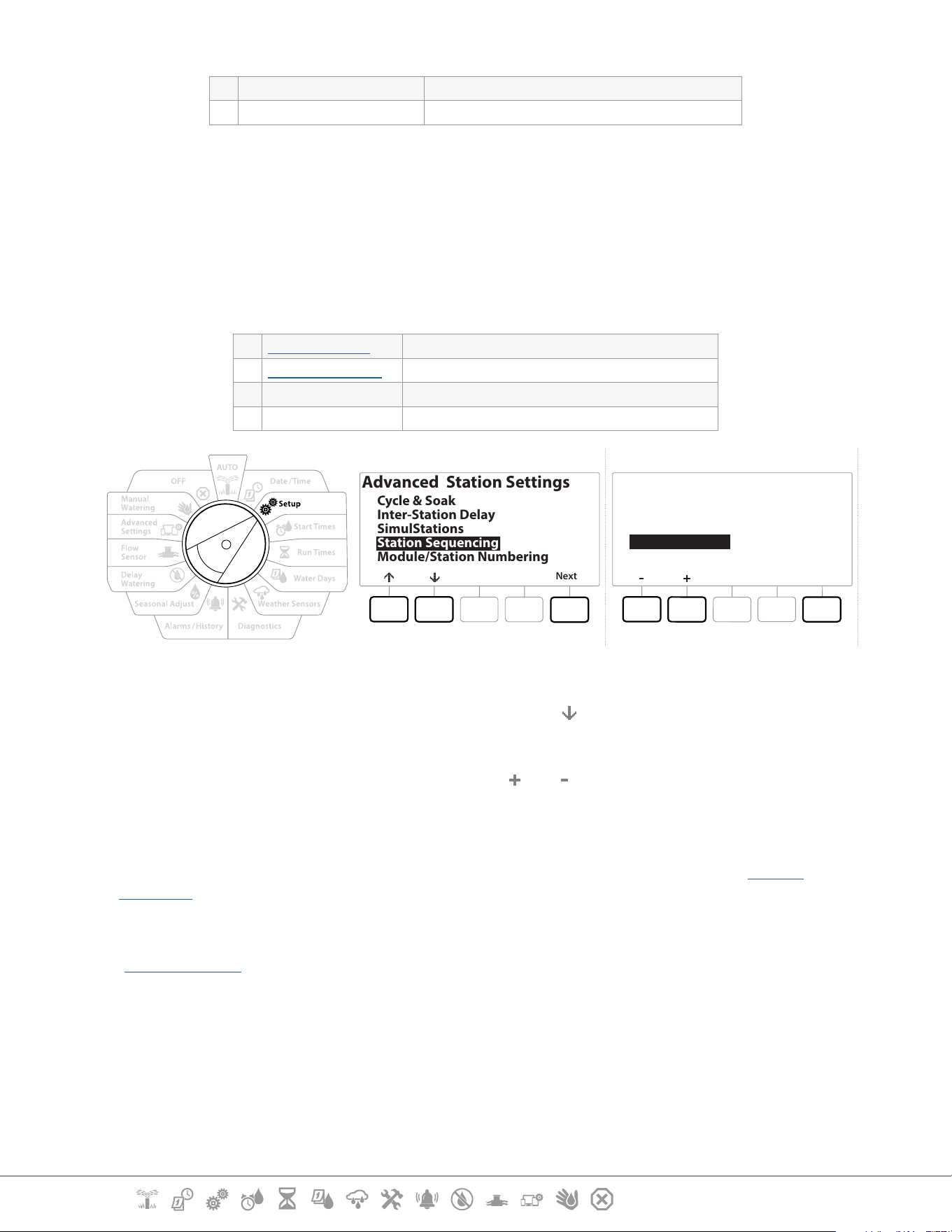
4.4.5 Station Sequencing (Advanced Station Settings)
Station sequencing only works with Flo-Manager™ turned o. It allows you to optimize water
windows by controlling the sequence in which stations can run. Stations can be sequenced by
Station Number or Station Priority.
Station Sequencing by Station Number (Default)
Stations will operate in the following order:
Current Section: Setup 31
Navigation:
1 Station Number (1-48) LXME2 has a capacity of 48 programs
2 Program Assignment (1-40) LXME2 has a 40 independent Programs available.
•
Non-irrigation priority stations will always be selected to operate rst
Station Sequencing by Station Priorities
This option is required when using Flo-Manager®. This option decreases the overall time required to
complete watering when operating multiple stations simultaneously.
Stations will operate in the following order:
1 Station priority Non-Irrigation > High > Medium > Low
2 Station Run Time Longest run time > shortest run time
3 Station number LXME2 has a capacity of 48 programs
4 Program assignment LXME2 has a 40 independent Programs available.
Next
Advanced Station Settings
Cycle & Soak
Inter-Station Delay
SimulStations
Station Sequencing
Module/Station Numbering
Done
Station Sequencing
Sequence by:
Station Numbers
1 Turn the controller dial to Setup
2 At the Advanced Station Settings screen, press the button to navigate to “Station
Sequencing”, then press Next .
3 At the Station Sequencing screen, press the and keys to set Station Sequencing by
either Station Numbers or Station Priorities, as desired.
•
If Flo-Manager® is turned ON, then the default Station Sequencing setting is Sequence by Station Priorities.
To select Station Sequencing by Station Number, Flo-Manager® must rst be turned OFF. See “Set Flo-
Manager®” or more details.
•
When Station Sequencing is set to Sequence by Station Priorities, you can still manually operate stations
in station number sequence using the Test All Stations option from the Manual Watering dial position. See
“Test All Stations” for more details.
Current Section: Setup 32
Navigation:
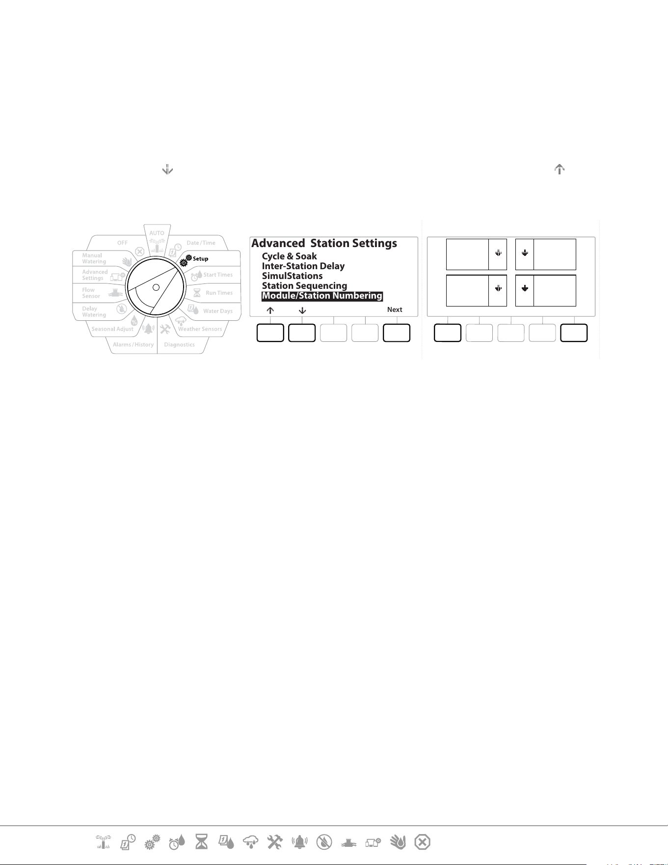
4.4.6 Module/ Station Numbering (Advanced Station Settings)
•
When a new module is installed the Module/ Station Numbering screen will be displayed automatically.
Making changes from the Setup dial position is not recommended at initial setup.
1 Turn the controller dial to Setup
2 Use the key to navigate to “Advanced Station Settings”, on this screen, Use the key
to navigate to “Module/ Station Numbering”, then press Next . Press Next again on the
dialog screen.
Next
Advanced Station Settings
Cycle & Soak
Inter-Station Delay
SimulStations
Station Sequencing
Module/Station Numbering
DoneChange
SM12 SM12
SM12SM12
01
1
2
3
4
12
25
36
37
48
13
24
AC
AL
BG
BP
3 The Module Status screen appears. The current status of any installed station modules is
displayed.
4 This screen can be used to change the labelling of the installed modules using the
Change key.
Current Section: Set Start Times 33
Navigation:
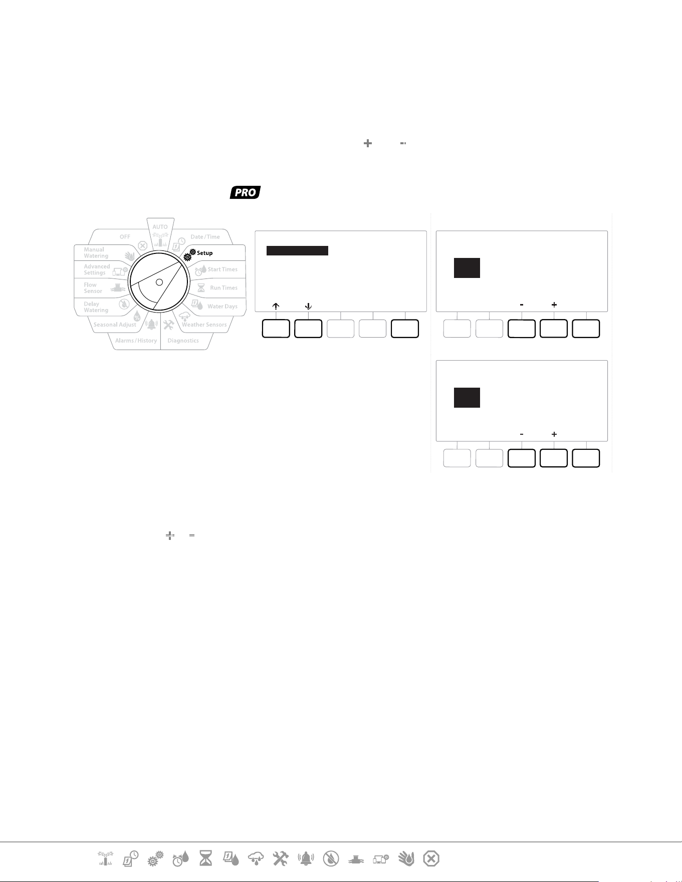
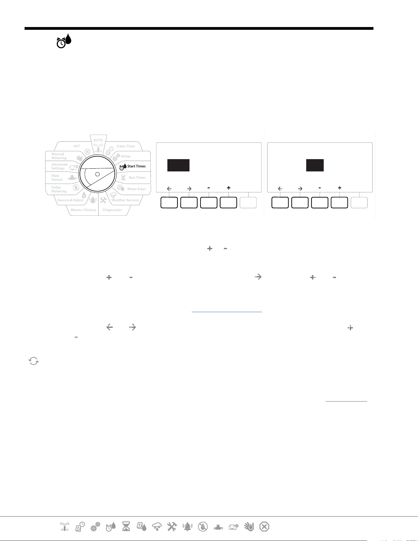
5. SET START TIMES
Start times are the time(s) of day that a program begins.
You can assign up to 10 Start Times to a single program. Multiple Start Times allow you to run a
program more than once on each day. For example, if you’re growing new lawn seed, you may want
to water several times a day to keep the seedbed or top dressing damp.
•
Start times apply to the entire program and not just to an individual station.
SET START TIMES
PGM 02
1st OFF
SET START TIMES
PGM 02
1st 12 : 00 PM
1 Turn the controller dial to Start Times
2 At the Set Start Times screen, press the or key to select the program you wish to
create Start Times for.
3 Press the and keys to set the hour, then press the key. Press the and keys to
set the minutes.
•
If the desired program is not selected, press the Program Select Button to change it.
4 Press the and keys to navigate between the number setting elds. Press the and
keys to set additional Start Times (1 through 10).
Use the Program Select button and repeat this process to set up additional Watering Start Times for other
programs as desired.
•
Cycle+Soak™ is an alternative method of dividing the total Station Run Time into smaller cycle times. If you
plan to use Cycle+Soak, only a single Watering Start Time is required for each program. See “Cycle+Soak™”
for more details.
Current Section: Run Times 34
Navigation:
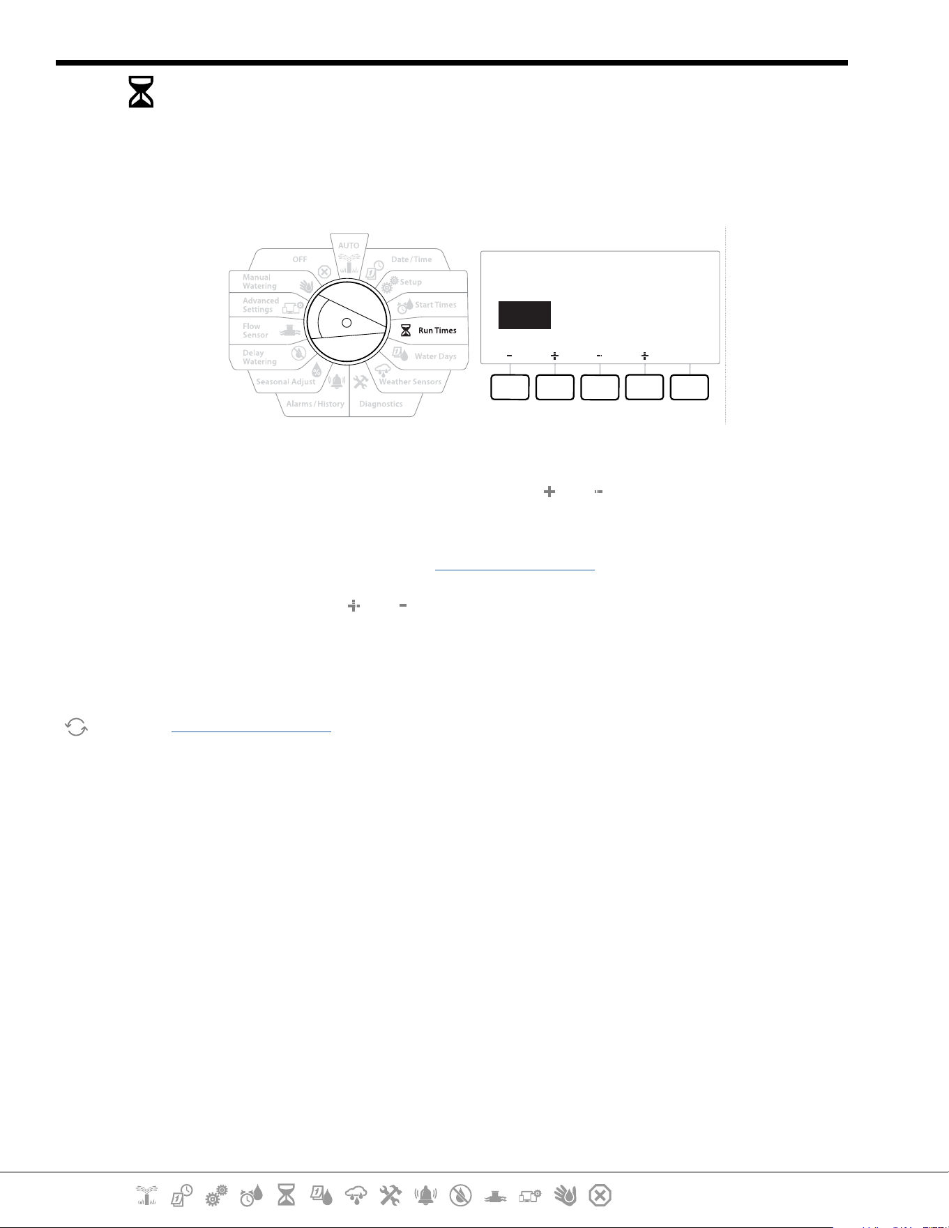
6. RUN TIMES
Run Times are the number of minutes (or hours and minutes) that each station runs.
Once your stations are set up, you can assign irrigation Run Times for each. Station Run Times are
particular to programs, so typically stations are set for a single program.
Copy
Station HH MM
SET RUN TIMES
PGM 01
001 00:00
1 Turn the controller dial to Run Times
2 At the Set Run Times screen, press the rst set of and keys to set the station to you
wish to create programs for.
•
If the desired program is not selected, press the Program Select Button to choose the desired program.
3 Press the second set of and keys to set the Station Run Time. Range can be from 00
hours, 00 minutes (no Run Time) up to 96:00 hours.
•
Press and HOLD keys to accelerate settings.
Use the Program Select Button to change the program and repeat this process to set up additional Station
Run Times for other programs as desired.
Current Section: Run Times 35
Navigation:
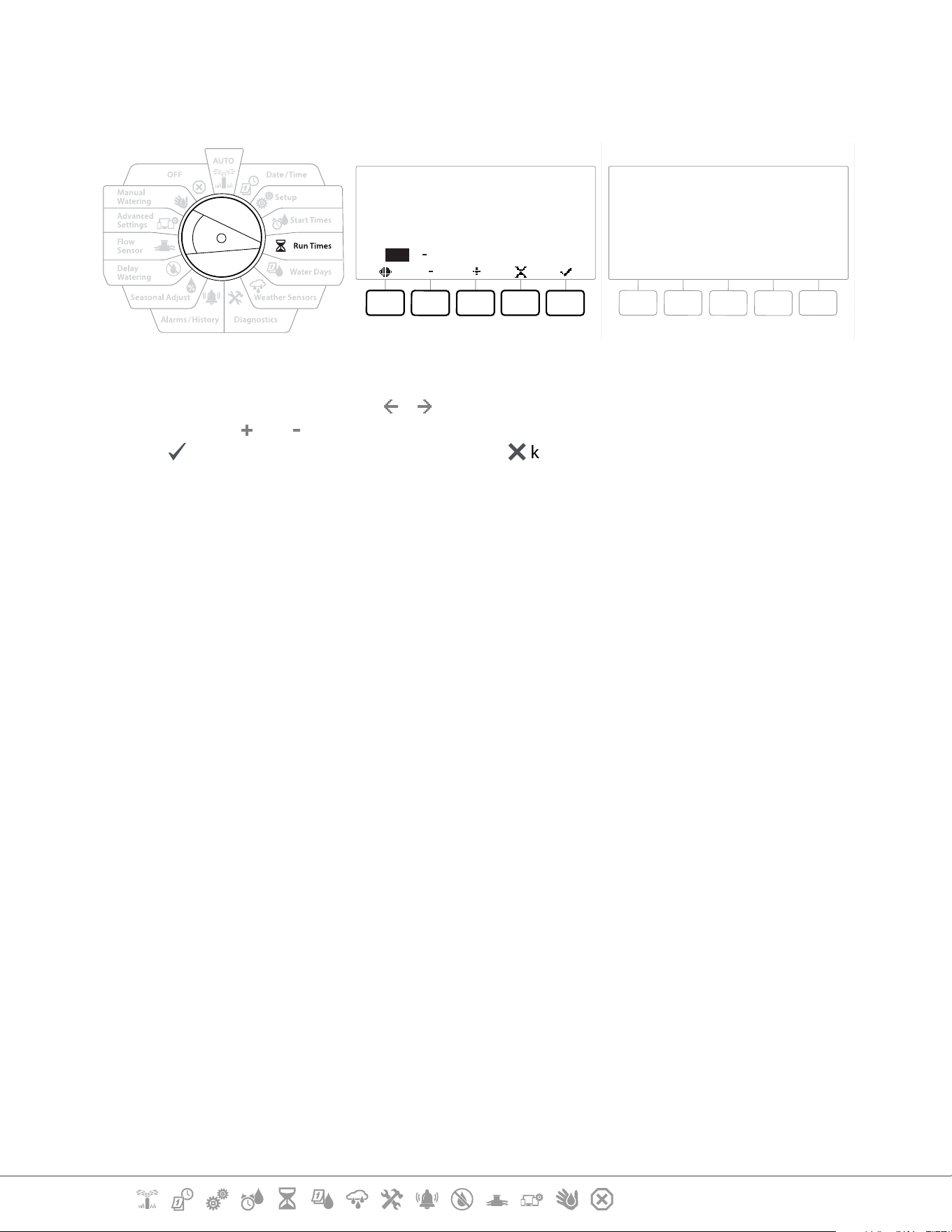
6.4.1 Copy Run Times
You can copy Station Run Times from one program to other programs.
Copy run time:
HH MM
01:20
001 003
to all stations between
PGM 01
Copied 01:20
PGM 01
Sta. 001 through Sta. 003
1 At the Set Run Times screen, press “Copy”.
2 At the Copy screen, use the & key to navigate between the number setting elds.
Press the and keys to set the desired starting and ending station numbers. Press the
✔
key to copy the station data, or press the
✖
key to cancel.
3 A conrmation screen shows the process is complete.
Current Section: Water Days 36
Navigation:
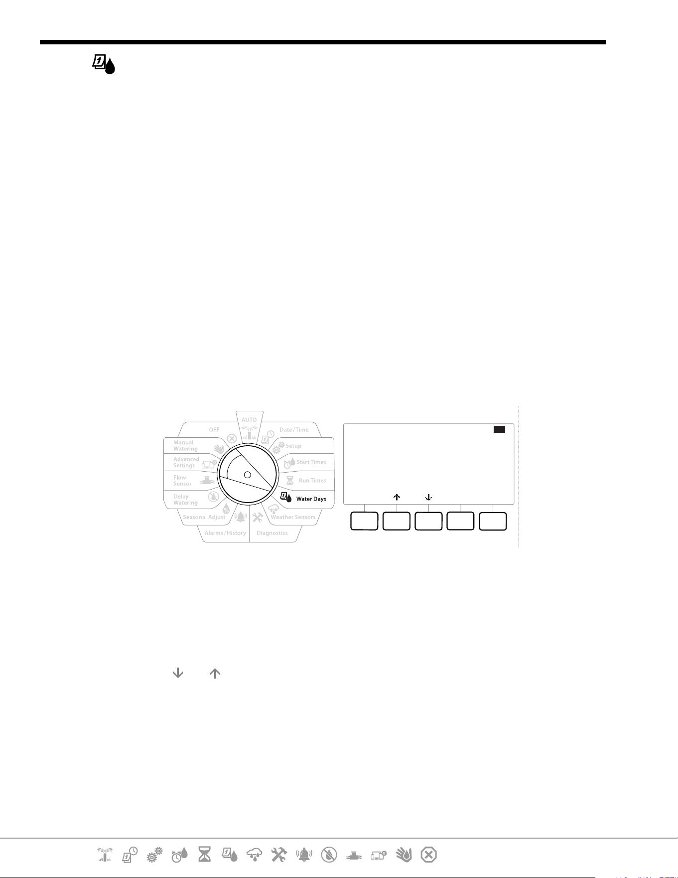
7. WATER DAYS
Watering Days are the specic days of the week on which irrigation is allowed to occur.
The LXME2 controller supports a variety of exible watering day cycle options.
• By Day of Week: irrigation starts at chosen individual days in the week where program starts are
allowed.
• Cyclic days: irrigation starts at regular chosen intervals such as every 3rd or 5th day, regardless of
the calendar date.
• Even Dates: irrigation starts on all even numbered calendar days, such as the 2nd, 4th, 6th, etc.
• Odd Dates: irrigation starts on all odd numbered calendar days, such as the 1st, 3rd, 5th, etc.
• Odd Dates no 31st: irrigation starts on all odd numbered calendar days, such as the 1st, 3rd, 5th,
etc., but not on the 31st.
•
Regardless of the Watering Cycle, irrigation will start only on days of the week where program starts are
allowed.
7.4.1 Custom, By Day of Week
Mode
Off On
Mon
Tue
Wed
Thu
Fri
Sat
Sun
On
On
Off
Off
Off
On
On
PGM01
By Day of Week
1 Turn the controller dial to Water Days
2 The Custom, By Day of Week screen appears.
3 Press the On key to allow irrigation on a given day of the week or else press Off to prevent
from starting on that day.
4 Press the
and keys to navigate through the days of the week.
Current Section: Water Days 37
Navigation:
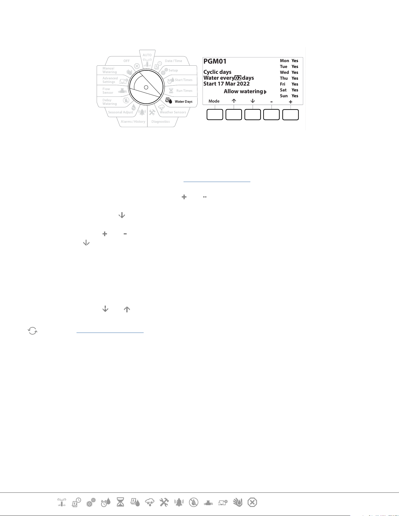
7.4.2 Cyclic Days
Mode
Mon
Tue
Wed
Thu
Fri
Sat
Sun
Yes
Yes
Yes
Yes
Yes
Yes
Yes
PGM01
Cyclic days
Water every 02 days
Start 17 Mar 2022
Allow watering
1 Turn the controller dial to Water Days
2 At the Watering Cycle screen, press the Mode key to navigate to the Cyclic Days screen.
•
If the desired program is not selected, press the Program Select Button to choose the desired program.
3 At the Day Cycle screen, press the and key to set the watering day cycle (from 1 to
30 days). For example, set to the day cycle to 03 if you want to water every third day,
then press the key.
4 Press the and keys to set the rst date for the Watering Cycle to begin, then press
the key.
•
Press and HOLD keys to accelerate settings.
5 Press the Yes key to allow irrigation to start on a given day of the week or else press No to
prevent irrigation from starting that day.
6 Press the and keys to navigate through the days of the week.
Press the Program Select Button and repeat this process to select Cyclical Watering for other programs as
desired.
Current Section: Water Days 38
Navigation:
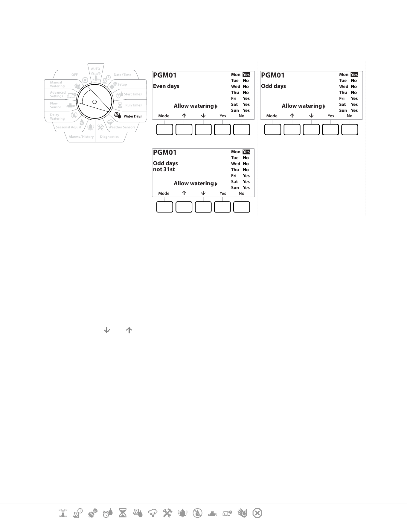
7.4.3 Even days, Odd days, Odd no 31st
The process for setting up Even, Odd, and Odd no 31st Watering Cycles is very similar.
Mode Yes No
Mon
Tue
Wed
Thu
Fri
Sat
Sun
Yes
No
No
No
Yes
Yes
Yes
PGM01
Even days
Allow watering
Mode Yes No
Mon
Tue
Wed
Thu
Fri
Sat
Sun
Yes
No
No
No
Yes
Yes
Yes
PGM01
Odd days
Allow watering
Mode Yes No
Mon
Tue
Wed
Thu
Fri
Sat
Sun
Yes
No
No
No
Yes
Yes
Yes
PGM01
Odd days
not 31st
Allow watering
1 Turn the controller dial to Water Days
2 At the Watering Cycle screen, press the Mode key to navigate to the Even days, Odd
days or Odd 31st screen.
•
If the desired program is not selected, press the Program Select button to choose the desired program. See
“Program Select Button” for more details.
3 Press the Yes key to allow irrigation to start on a given day of the week or else press No to
prevent irrigation from starting that day.
4 Press the and to navigate through the days of the week.
Current Section: Weather Sensors 39
Navigation:
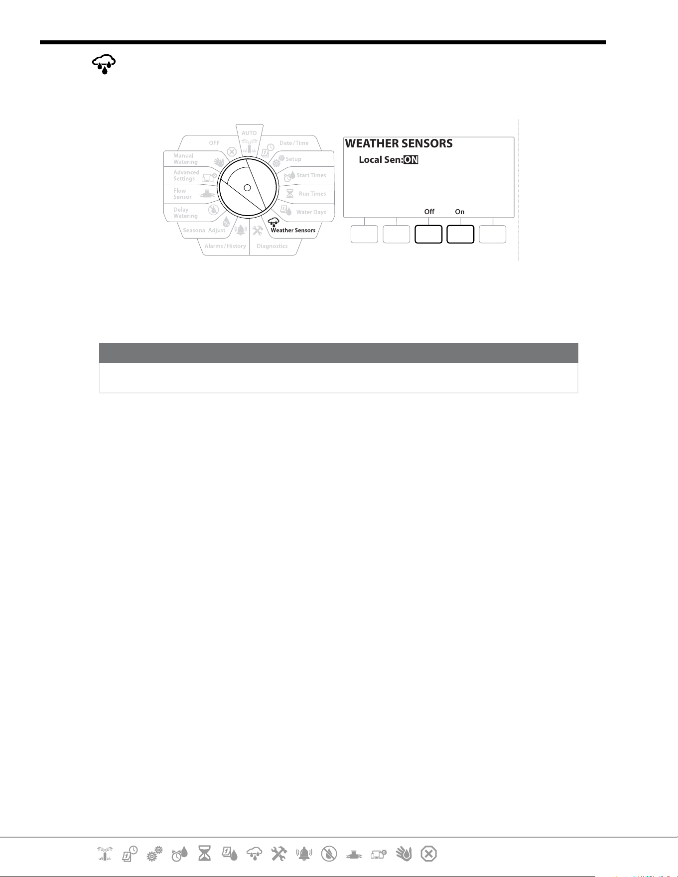
8. WEATHER SENSORS
The LXME2 can accept input from a single weather sensor wired directly to the controller.
Off On
WEATHER SENSORS
Local Sen: ON
1 Turn the controller dial to Weather Sensors
2 At the Weather Sensors screen, press the On key to activate the local Weather Sensor or
else press O to bypass.
NOTICE
Follow the sensor manufacturer’s instructions to correctly install and make wire connections to the sensor.
Ensure the sensor installation is in compliance with all local codes.
Supported Rain Bird® Weather Sensors:
• RSD rain shut o device
• WR2-RC wireless rain sensor
• WR2-RFC wireless rain/freeze sensor
Current Section: Diagnostics 40
Navigation:
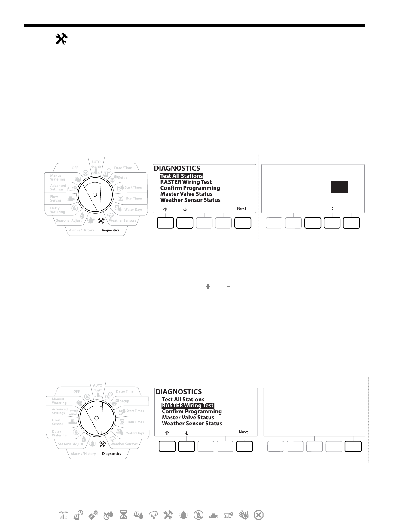
9. DIAGNOSTICS
9.4.1 Test all Stations
You can test all stations connected to the controller by running each of them in station number
sequence.
This feature can be useful after installation, for general maintenance or as a rst step in
troubleshooting your system.
•
Only stations with programmed run times are included in the Test All Stations operation.
DIAGNOSTICS
Next
Test All Stations
RASTER Wiring Test
Confirm Programming
Master Valve Status
Weather Sensor Status
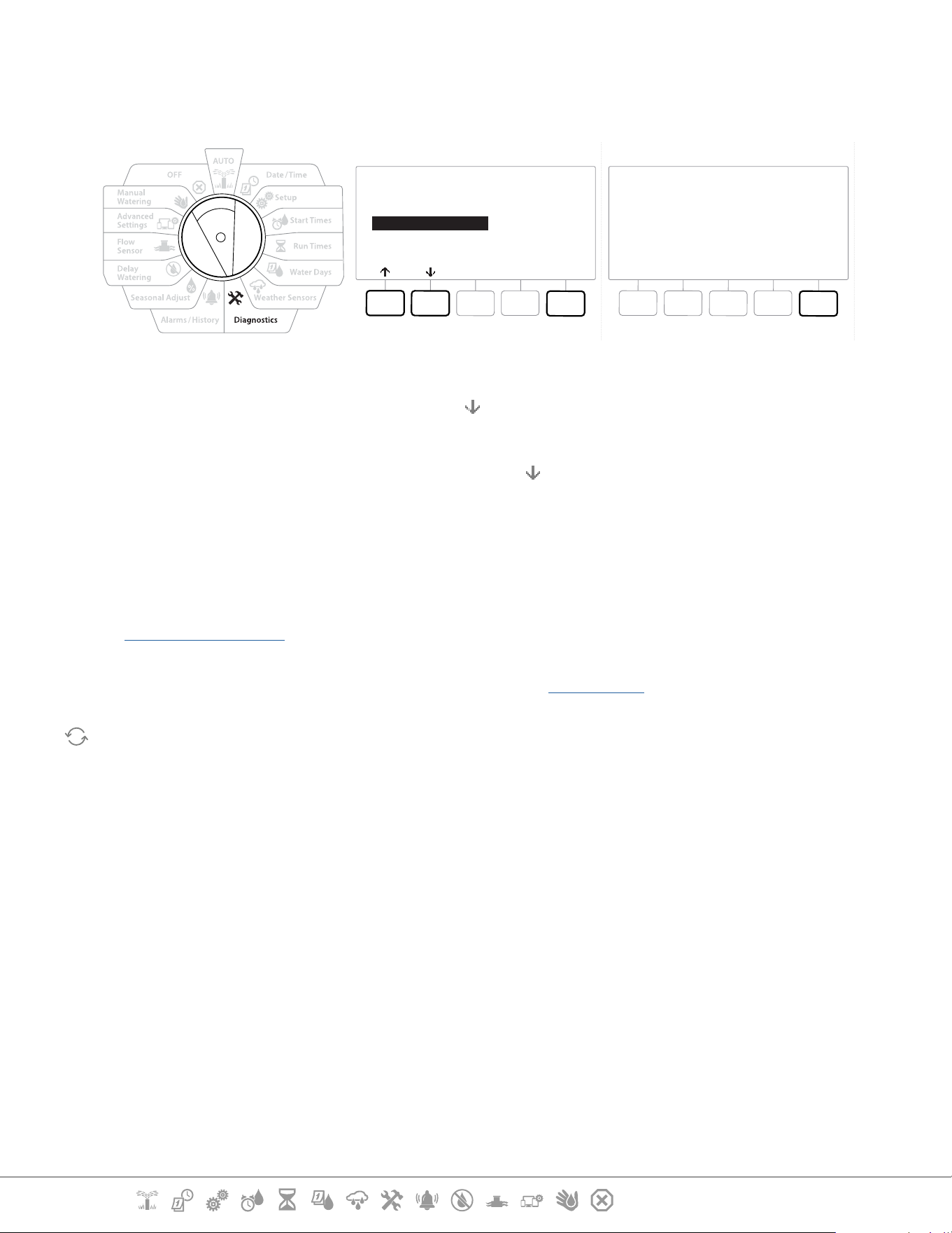
Test All Stations
10Test Time
Run
Minutes
1 Turn the controller dial to Diagnostics
2 At the Diagnostics screen, with “Test All Stations” selected, press Next .
3 At the Test All Stations screen, press the and keys to set the desired time (from 1 to
10 minutes), then press “Run”.
4 A conrmation screen shows the test has started.
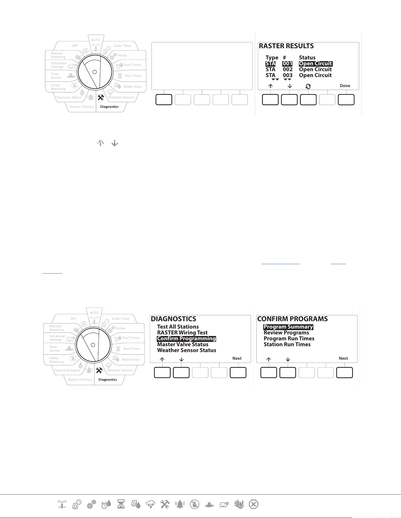
9.4.2 Raster Wiring Test
The ESP-LXME controller can quickly test to determine if any stations have shorted or if there are
open wires or valve solenoids.
DIAGNOSTICS
Next
Test All Stations
RASTER Wiring Test
Confirm Programming
Master Valve Status
Weather Sensor Status
RASTER WIRING TEST
Run
Do not Remove/Insert Modules
during test
Modules Detected: 4
Total Stations: 48
Current Section: Diagnostics 41
Navigation:
RASTER WIRING TEST
Cancel
Testing in Progress
Station #008
RASTER RESULTS
Done
Type
STA
STA
STA
#
001
002
003
Status
Open Circuit
Open Circuit
Open Circuit
1 Turn the controller dial to Diagnostics
2 Use the
& arrows to navigate to “RASTER Wiring Test”, press Next
3 The Raster Wiring Test screen will display there Modules Detected (this should be the
number of wiring modules installed). And the total number of Stations.
4 Press the “Run” button to begin the wiring test.
•
The Raster Wiring Test will take up to a few minutes. Each installed station will be displayed on the screen in
sequence as the controller tests them.
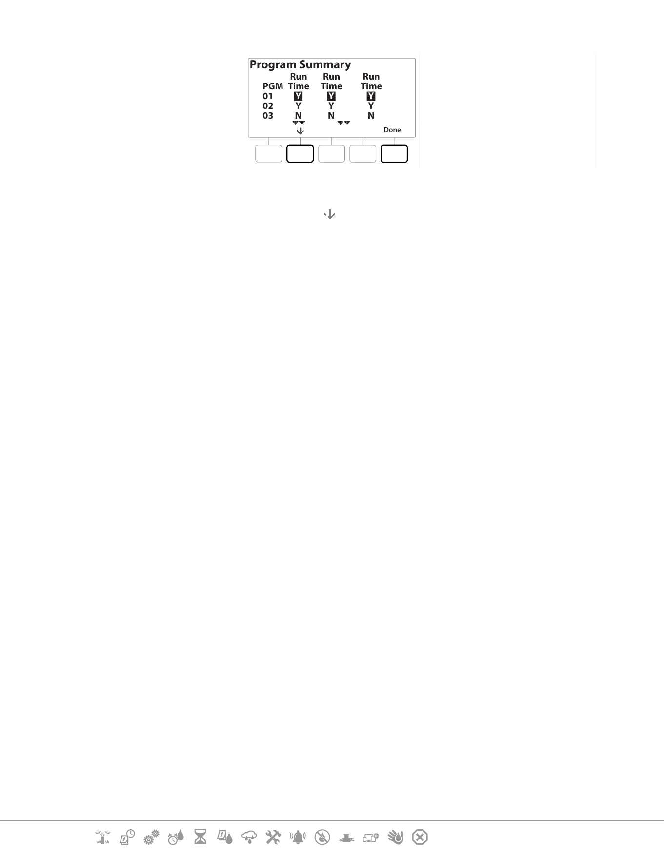
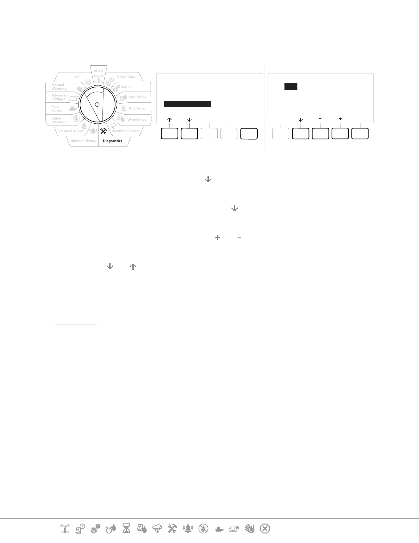
9.4.3 Conrm Programming
The LXME2 controller can make calculations and provide feedback on Start Times and total Run
Times for programs and stations.
9.4.4 Program Summary
DIAGNOSTICS
Next
Test All Stations
RASTER Wiring Test
Confirm Programming
Master Valve Status
Weather Sensor Status
CONFIRM PROGRAMS
Next
Program Summary
Review Programs
Program Run Times
Station Run Times
Current Section: Diagnostics 42
Navigation:
Program Summary
Done
PGM
01
02
03
Run
Time
Y
Y
N
Run
Time
Y
Y
N
Run
Time
Y
Y
N
1 Turn the controller dial to Diagnostics
2 At the DIAGNOSTICS screen, press the key to select “Confirm Programming”, then press
Next .
3 At the CONFIRM PROGRAMS screen, with “Program Summary” selected, press Next .
4 The Program Summary screen appears, providing a summary of Run Times, Start Times
and Water Days for all programs.
In the example above:
• Program 1 and 2 will run because they have Station Run Time, Start Time and Water Days all
programmed, as indicated by the “Y” in each column.
• Program 3 will not run as it is missing all programming, as indicated by the “N” in each column.
Current Section: Diagnostics 43
Navigation:
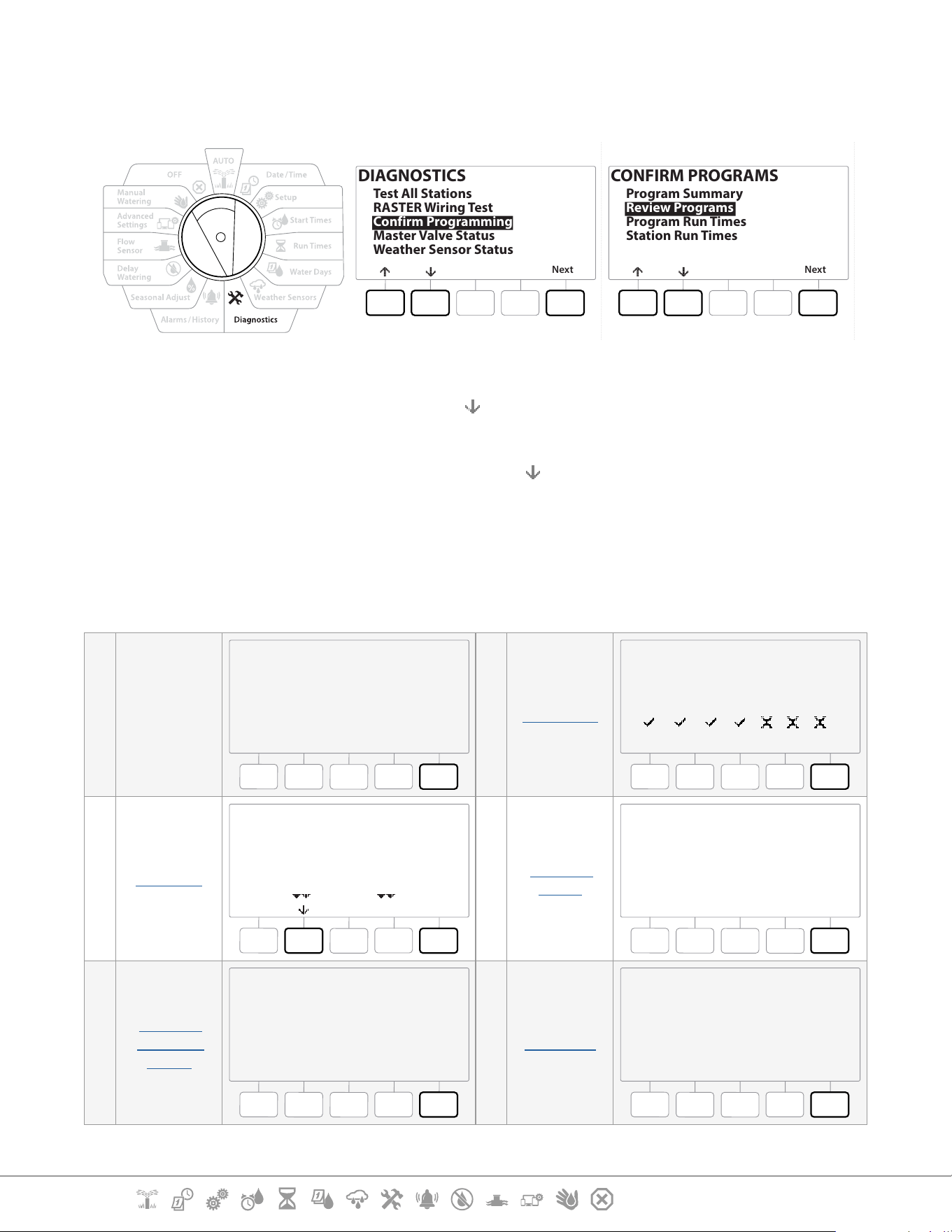
9.4.5 Review Programs
Review program information for a station.
DIAGNOSTICS
Next
Test All Stations
RASTER Wiring Test
Confirm Programming
Master Valve Status
Weather Sensor Status
CONFIRM PROGRAMS
Next
Program Summary
Review Programs
Program Run Times
Station Run Times
1 Turn the controller dial to Diagnostics
2 At the DIAGNOSTICS screen, press the key to select “Confirm Programming”, then press
Next .
3 At the CONFIRM PROGRAMS screen, press the key to select “Review Programs”, then
press Next .
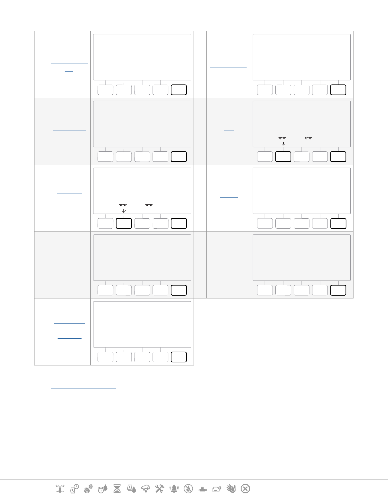
4 The following screens provide a complete summary of the LXME2’s programming.
Pressing the Next button will allow you to progress from screen to screen, while pressing
the Back button take you back to the previous screen. Some of the screens will allow
you to make programming changes directly using the programming buttons.
1
Program
Summary
PGM 01
Next
1
2
3
4
5
01:00
02:00
03:00
04:00
05:00
OFF
OFF
OFF
OFF
OFF
6
7
8
9
10
Watering Start Times
2 Water Days
PGM 01
Next
Mo Tu We Th Fr Sa Su
Water Days
Cyclic
3 Run times
PGM 01
Next
STA
001
002
003
HH:MM
01:20
00:30
00:15
Run Times
4
Seasonal
Adjust
PGM 01
100%
Next
Seasonal Adjust
5
Seasonal
Adjust By
Month
PGM 01
Next
Seasonal Adjust
by Month
Not used by PGM01
6 Rain Delay
Rain Delay
Next
From:
To:
---
---
Irrigation will run after selected
date
Current Section: Diagnostics 44
Navigation:
7
Calendar Day
O
Calender Day Off
Next
No Calender
Days Off
8 Station Delay
PGM01
Next
Station Delay
Delay Between Stations
03:10
MM:SS
9
Cycle+Soak
Minutes
Cycle+Soak Minutes
Next
STA
001
002
003
Cycle
10
10
10
Soak
05
05
05
10
MV
Assignment
MV Assignment
Next
STA
001
002
003
004
FZ
-
1
1
1
MV1
N
Y
Y
Y
2
N
N
N
N
11
Weather
Sensor
Assignment
MV Assignment
Next
STA
001
002
003
004
Loc
N
Y
Y
Y
12
Water
Window
PGM 01
Next
Open:
Closed:
Duration:
OFF
OFF
N/A
HH:MM
Water Window
13
Program
SimulStations
PGM 01
Next
Program
SimulStations
Maximum Number of
SimulSations
Irrigation 5
14
Controller
SimulStations
Next
Controller
SimulStations
Maximum Number of
SimulSations
Irrigation 1
Non-Irrigation 1
15
Contractor
Default
Delayed
Recall
Backup
Next
Controller Default
Backup Not Stored
•
If the desired program is not selected, press the Program Select button to choose the desired program. See
“Program Select Button” for more details.
Current Section: Diagnostics 45
Navigation:
9.4.6 Program Run Times
Review total Run Time for an individual program.
CONFIRM PROGRAMS
Next
Program Summary
Review Programs
Program Run Times
Station Run Times
Done
Total RunTime
HHHHHH:MM
000110:30
PGM 01
1 Turn the controller dial to Diagnostics
2 At the DIAGNOSTICS screen, press the key to select “Confirm Programming”, then press
Next .
3 At the CONFIRM PROGRAMS screen, press the key to select “Program Run Times”, then
press Next .
4 The Total Run Time screen appears and total Run Time is shown for the currently
selected program.
•
If the desired program is not selected, press the Program Select button to choose the desired program. See
“Program Select Button” for more details.
•
For stations set up for Cycle+Soak, the Cycle Time (when irrigation is occurring) will be included in Program
RunTime calculations but Soak times will NOT be included. See “Cycle+Soak™” for more details.
Use the Program Select button to change the program and repeat this process to review and conrm
Program Run Times for other programs as desired.
Current Section: Diagnostics 46
Navigation:
9.4.7 Station Run Times
Review total Run Time for all stations.
CONFIRM PROGRAMS
Next
Program Summary
Review Programs
Program Run Times
Station Run Times
Station Run Times
STA 001
Done
PGM 01
PGM 02
HH:MM
01:20
02:00
1 Turn the controller dial to Diagnostics
2 At the DIAGNOSTICS screen, press the key to select “Confirm Programming”, then press
Next .
3 At the CONFIRM PROGRAMS screen, press the key to select “Station Run Times”, then
press Next .
4 At the Station Run Time screen, press the and keys to select the desired Station.
Station Run Times are shown for the currently selected station in all programs.
5 Press the and to scroll the list of programs. For Stations where a particular Program
is not used then no run time is shown.
•
To make changes make Run Time changes see “Run Times”.
•
Soak times for stations set up with Cycle+Soak are not included in the Station Run Time calculations. See
“Cycle+Soak™” for more details.
Current Section: Diagnostics 47
Navigation:
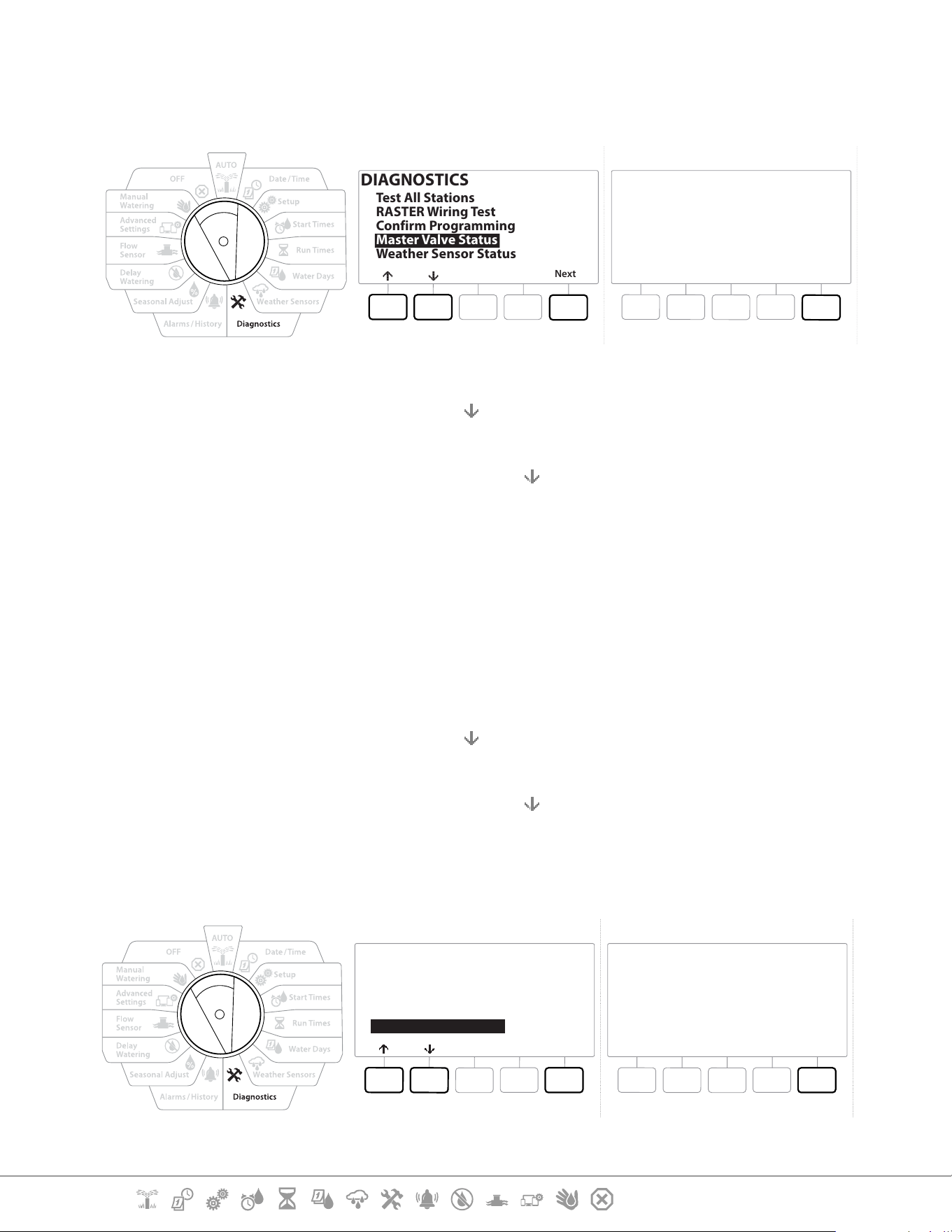
9.4.8 Master Valve Status
Review status of Master Valves.
DIAGNOSTICS
Next
Test All Stations
RASTER Wiring Test
Confirm Programming
Master Valve Status
Weather Sensor Status
Master Valves
Done
MV
1
2
Type
NCMV
PUMP
Status
Open
Open
MVWW
N
N
1 Turn the controller dial to Diagnostics
2 At the DIAGNOSTICS screen, press the key to select “Confirm Programming”, then press
Next .
3 At the CONFIRM PROGRAMS screen, press the
key to select “Review Master Valves”, then
press Next .
4 The Master Valves screen appears, showing installed master valves, their type (Normally
Closed or Normally Open), their current status (open or closed) and if they are included
in the MV Water Window (MVWW) (Yes or No).
9.4.9 Weather Sensor Status
1 Turn the controller dial to Diagnostics
2 At the DIAGNOSTICS screen, press the key to select “Confirm Programming”, then press
Next .
3 At the CONFIRM PROGRAMS screen, press the key to select “Weather Sensor Status”, then
press Next .
4 The Weather Sensor Status screen displays the current status of the local weather sensor
as either On or O.
DIAGNOSTICS
Next
Test All Stations
RASTER Wiring Test
Confirm Programming
Master Valve Status
Weather Sensor Status
Done
Weather Sensors
Sensor
Local
Status
On
Current Section: Alarms/ History 48
Navigation:
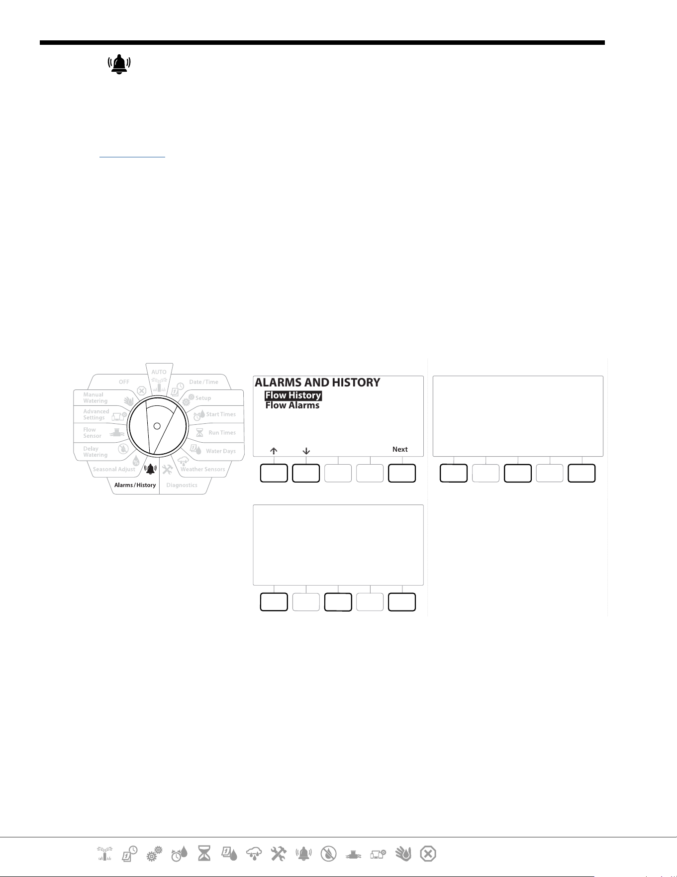
10. ALARMS/ HISTORY
10.4.1 Flow History
With Flo-Watch™ enabled, the controller will automatically track the volume of water owing
through the system.
•
This can be useful for checking your actual water consumption against your water bill.
1 Turn the controller dial to Alarms/History
2 At the ALARMS AND HISTORY screen, with “Flow History” selected, press Next .
3 The Flow History screen appears, showing month-to-date and last month water
consumption.
•
Press the Days key to change the view to the last 30 days and previous 30 days.
ALARMS AND HISTORY
Next
Flow History
Flow Alarms
Flow History
DoneClearMonths
Last 30 Days
0 Gal
Prior 30 Days
0 Gal
Flow History
DoneClearMonths
Last 30 Days
0 Gal
Prior 30 Days
0 Gal
10.4.2 Clear Flow History
1 At the Clear Flow History conrmation screen, press the Yes key to continue. If you’re not
sure, press the No key.
2 The conrmation screen appears, showing that Flow History has been cleared, resetting
the ow to 0.
•
Pressing Clear from either the monthly or daily screen will clear BOTH monthly and daily ow log data.
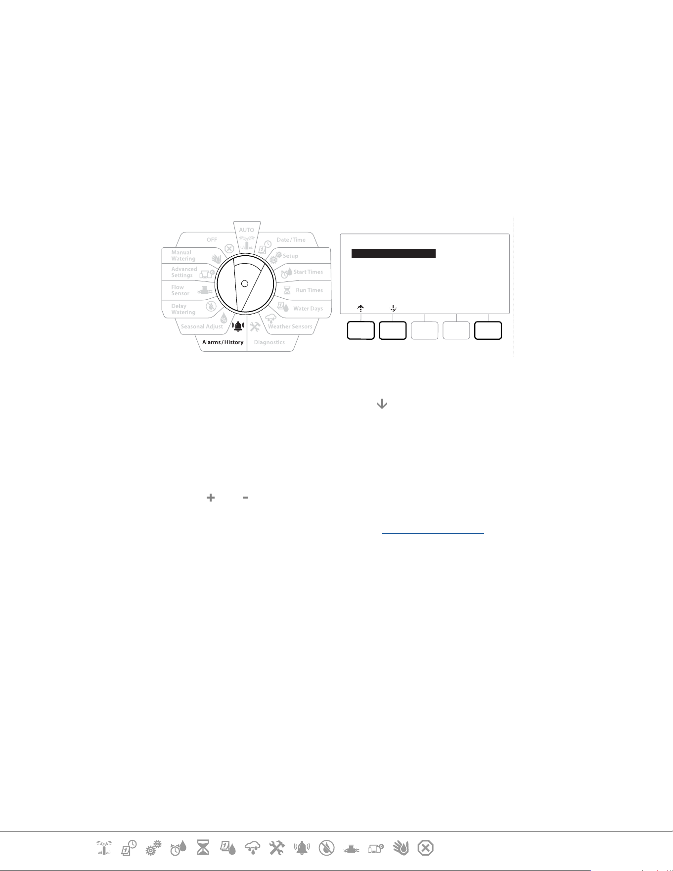
Current Section: Alarms/ History 49
Navigation:
10.4.3 Flow Alarms
The LXME2 controller can be set up to issue alarms when ow conditions are in excess of your High
Flow settings or below your Low Flow settings.
Occasionally a ow condition will be detected If the controller is set up to issue alarms for these
conditions, the alarm light will illuminate and detailed descriptions of the Flow Alarm conditions will
be created.
Station Flow Alarms
Flow Alarms
Next
Station Flow Alarms
FloZone Flow Alarms
Clear Flow Alarms
1 Turn the controller dial to Alarms/History
2 At the ALARMS AND HISTORY screen, press the key to select “Flow Alarms”, then press
Next .
3 At the Flow Alarms screen, with “Station Flow Alarms” selected, press Next .
4 The Station Flow Alarms screen appears, showing the rst station where there is an
alarm. Press the and keys to view the Next Station Flow Alarm.
5 Note each station which has an alarm, then see “Clear Flow Alarms” below for more
details on how to clear ow alarms.
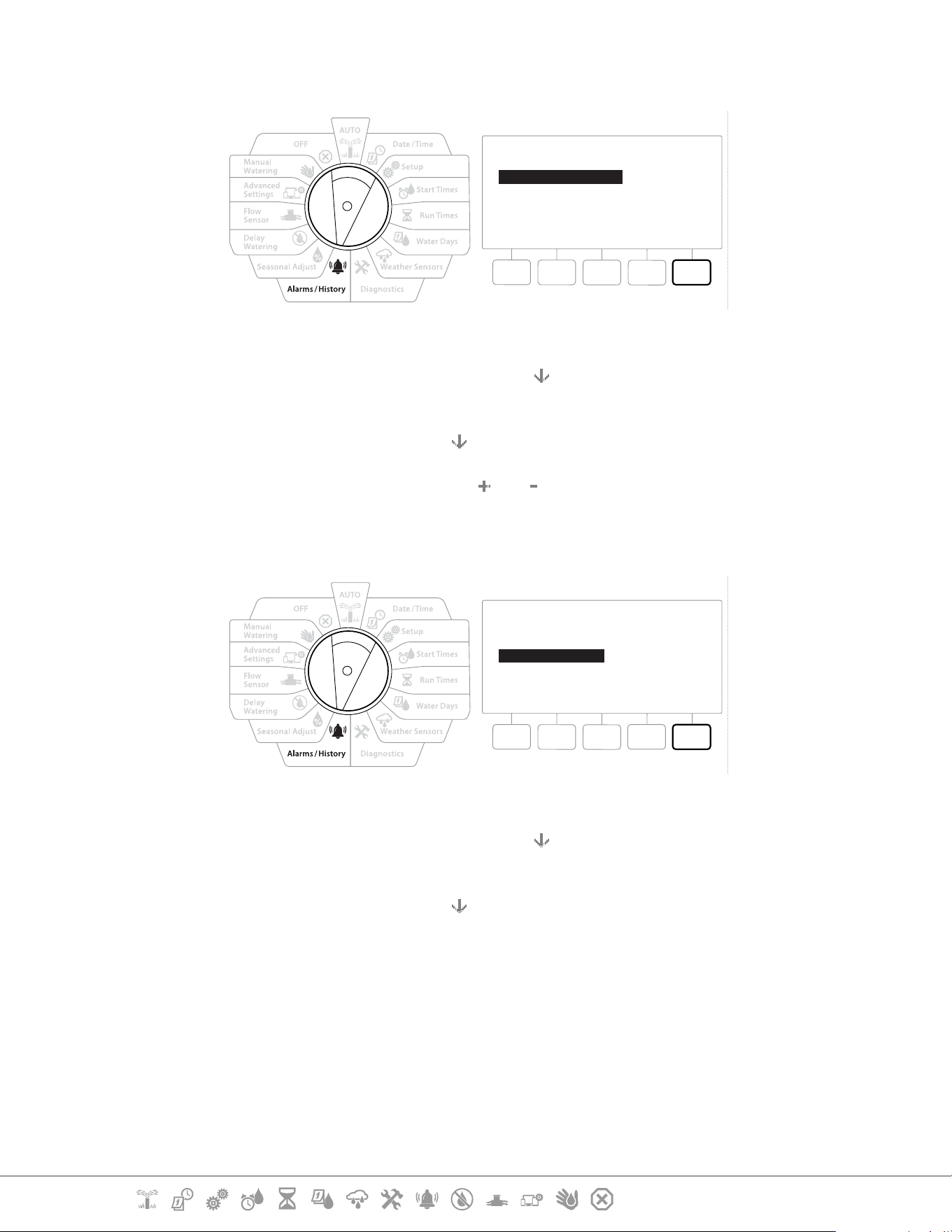
Current Section: Alarms/ History 50
Navigation:
FloZone Flow Alarms
Flow Alarms
Done
Station Flow Alarms
FloZone Flow Alarms
Clear Flow Alarms
1 Turn the controller dial to Alarms/History
2 At the ALARMS AND HISTORY screen, press the
key to select “Flow Alarms”, then press
Next .
3 At the Flow Alarms screen, press the key to select “FloZone Flow Alarms”, then press Next .
4 At the FloZone Alarms screen, press the and keys to view other FloZone ow alarms.
Clear Flow Alarms
Flow Alarms
Done
Station Flow Alarms
FloZone Flow Alarms
Clear Flow Alarms
1 Turn the controller dial to Alarms/History
2 At the ALARMS AND HISTORY screen, press the
key to select “Flow Alarms”, then press
Next .
3 At the Flow Alarms screen, press the
key to select “Clear Flow Alarms”, then press Next .
4 The Clear All Flow Alarms screen appears. Press Yes to clear all Station and FloZone Flow
Alarms.
5 A conrmation screen shows that Flow Alarms have been cleared.
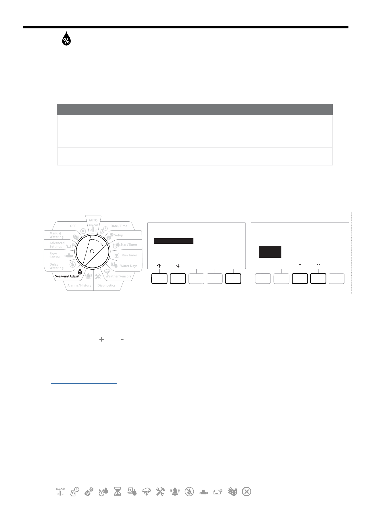
Current Section: Seasonal Adjust 51
Navigation:
11. SEASONAL ADJUST
Seasonal Adjust allows you to use the heaviest irrigation season as a baseline so that lesser amounts
of watering occur during those seasons.
For example, you could set July at 100% and set October to 50% so there would be half as much
watering in Fall than in Summer. Seasonal adjustments can be managed by month or by program.
NOTICE
Multiple Seasonal Adjustment settings aect each other and can signicantly impact irrigation. For
example, if you set a program-level Seasonal Adjustment of 10% and then a monthly Seasonal Adjustment
of 10% then irrigation will be reduced to 1% of normal (10% of 10%). Consider using only one type of
Seasonal Adjustment setting.
Setting a small number for the Seasonal Adjustment percentage will greatly reduce watering and setting
to 0% will cancel irrigation entirely. Use caution when making Seasonal Adjustment settings.
11.4.1 Individual Program
Seasonal Adjust can be set to adjust by individual program.
SEASONAL ADJUST
Next
Individual PGM
By Month
Seasonal Adjust
by Program
PGM 01
100 %
1 Turn the controller dial to Seasonal Adjust.
2 At the SEASONAL ADJUST screen, with “Individual Program” selected, press Next .
3 Press the and keys to set the seasonal adjustment percentage (from 0 - 300% ).
•
Press and HOLD keys to accelerate settings.
•
If the desired program is not selected, press the Program Select button to choose the desired program. See
“Program Select Button” for more details.
11.4.2 By Month
% Adjust
Seasonal Adjust can be set to adjust by the specic month.
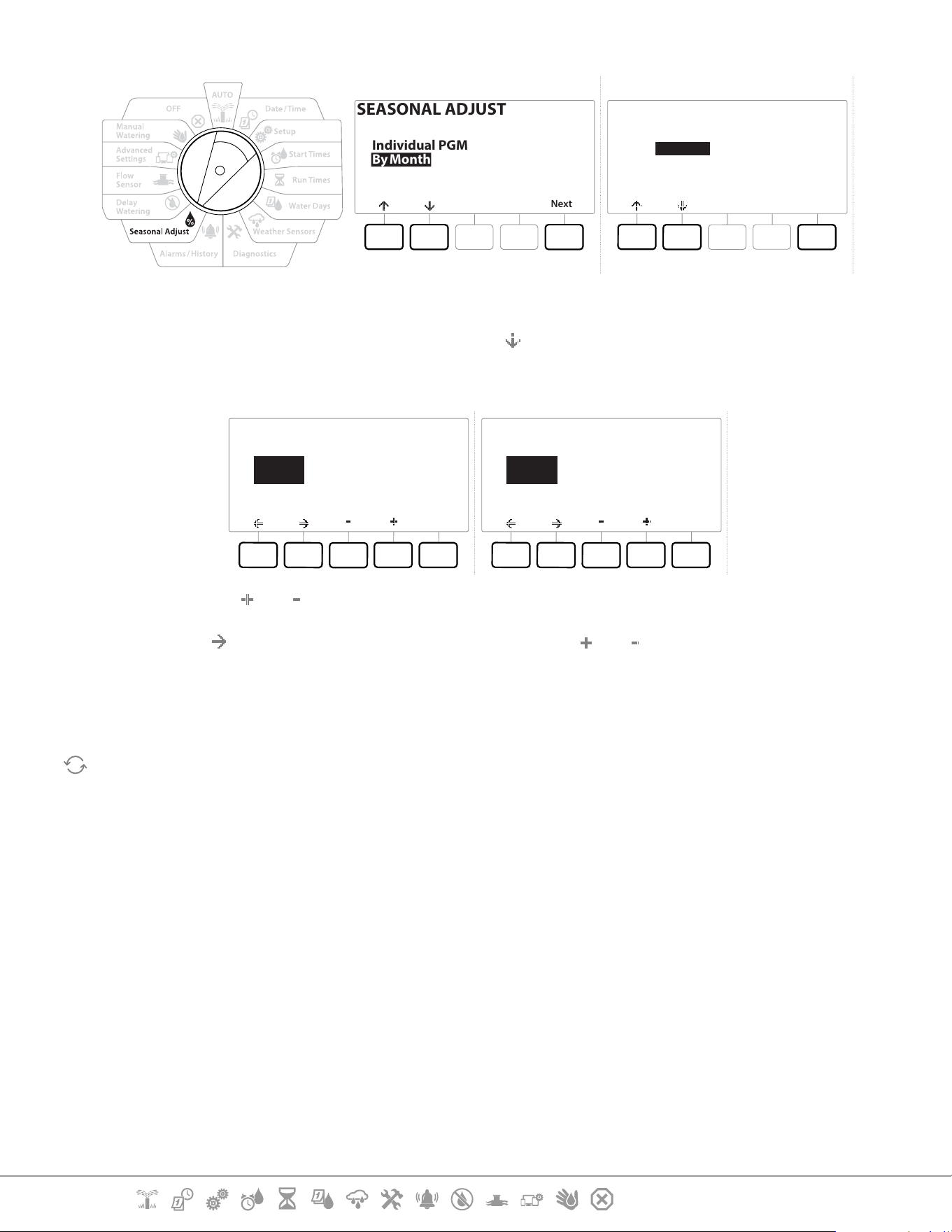
Current Section: Seasonal Adjust 52
Navigation:
SEASONAL ADJUST
Next
Individual PGM
By Month
Seasonal Adjust
by Month
Next
% Adjust
Select PGMs
1 Turn the controller dial to Seasonal Adjust
2 At the SEASONAL ADJUST screen, press the
key to select “By Month,” then press Next .
3 At the Seasonal Adjust by Month screen, with “% Adjust” selected, press Next .
Done
Seasonal Adjust
by Month
Jan 20%
Done
Seasonal Adjust
by Month
Jul 120%
4 Press the and keys to select the month you would like to adjust.
5 Press
to select the percentage eld. Then press the and keys to set the percentage
(from 0 - 300% ).
•
Press and HOLD keys to accelerate settings.
Repeat this process to set Seasonal Adjustments for other months as desired. Use the Program Select button
to change the program and repeat this process to set Seasonal Adjustments By Month for other programs as
desired.
•
The % Adjust will automatically change to the new month’s percentage setting on the rst day of the month.
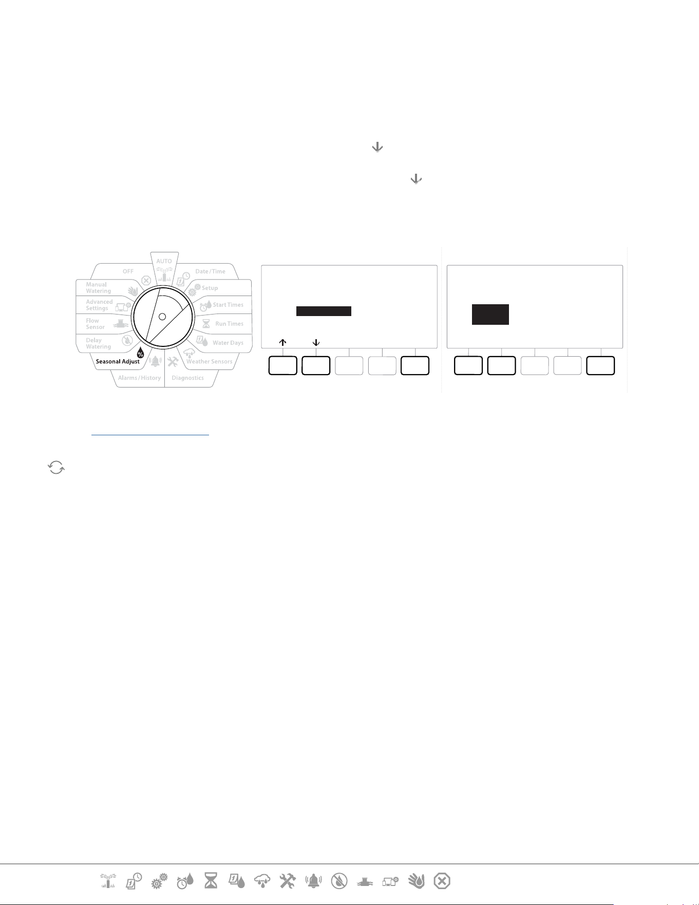
Current Section: Seasonal Adjust 53
Navigation:
Select Programs
Seasonal Adjust can be set to adjust by program for specic months.
1 Turn the controller dial to Seasonal Adjust
2 At the SEASONAL ADJUST screen, press the key to select “By Month”, then press Next .
3 At the Seasonal Adjust by Month screen, press the key to choose “Select PGMs”, then
press Next .
4 Press the Yes or No keys to set Monthly Adjust for the current selected program.
Seasonal Adjust
by Month
Next
% Adjust
Select PGMs
DoneYes No
PGM 01
Yes
Use Monthly Adjust
•
If the desired program is not selected, press the Program Select button to choose the desired program. See
“Program Select Button” for more details.
Repeat this process to set Monthly Adjustments for other programs as desired.
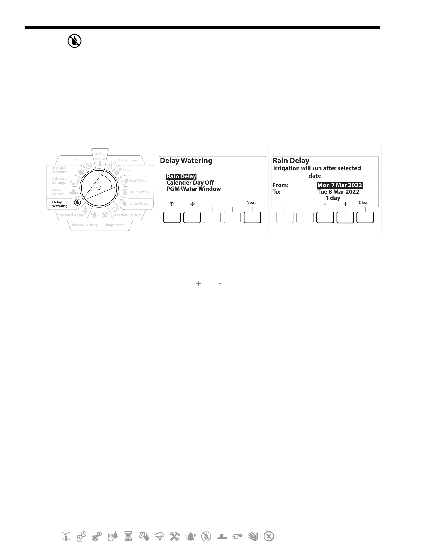
Current Section: Delay Watering 54
Navigation:
12. DELAY WATERING
12.4.1 Rain Delay
The LXME2 controller’s Rain Delay feature lets you discontinue irrigation for a few days after a period
of heavy rain.
•
If you have a rain sensor attached to the controller, it may be unnecessary to manually program a Rain
Delay. Consult the rain sensor device documentation for more details.
Delay Watering
Next
Rain Delay
Calender Day Off
PGM Water Window
Rain Delay
Clear
From:
To:
Mon 7 Mar 2022
Tue 8 Mar 2022
Irrigation will run after selected
date
1 day
1 Turn the controller dial to Delay Watering
2 At the Delay Watering screen, with Rain Delay selected, press Next .
3 At the Rain Delay screen, press the and keys to set the number of days (from 0 to 30
days). Press the Clear key if you want to cancel the Rain Delay.
•
Conrmation of Rain Delay will display in the AUTO dial position.
•
The next irrigation date after the Rain Delay calculates and shows automatically.
•
A Rain Delay aects all programs, but stations set up as Non-irrigation will still run during a Rain Delay.
12.4.2 Calendar Day O
The LXME2 controller can be programmed to suspend irrigation on a particular calendar date, for up
to 15 days of the year.
You can schedule certain days of the year as Non-irrigation, such as holidays when landscape may
receive heavy use.
•
Calendar Day O dates can only be selected 365 days in advance. Then once a Calendar Day O has passed,
it will be removed from the list and must be reprogrammed for the following year if desired.
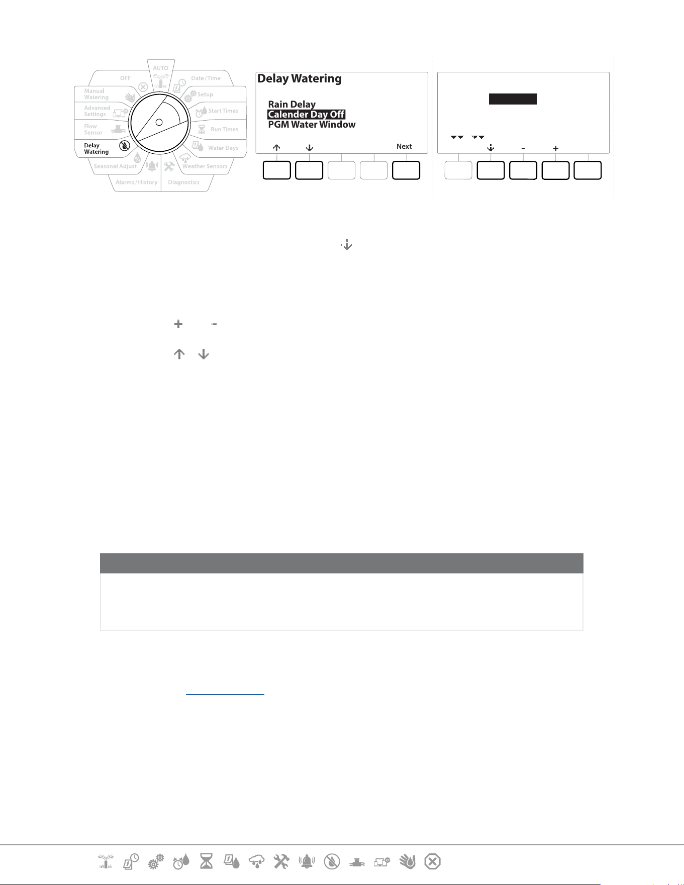
Current Section: Delay Watering 55
Navigation:
Delay Watering
Next
Rain Delay
Calender Day Off
PGM Water Window
Calender Day Off
Done
Day 1:
Day 2:
Day 3:
Day 4:
8 Mar 2022
Unused
Unused
Unused
1 Turn the controller dial to Delay Watering
2 At the Delay Watering screen, press the key to select “Calendar Day Off”, then press Next .
3 The Calendar Day o screen appears, showing (up to 5) scheduled calendar days o in
chronological order. Unprogrammed days will show as Unused.
4 Press the
and keys to set the Calendar Day O date as desired.
5 Press the & buttons to set other days as desired.
•
Press and HOLD keys to accelerate settings.
•
Calendar Day O aects ALL programs and stations, including non-irrigation stations. Consider not using
this feature if any of your programs include essential functions such as door locks or sports eld lighting.
12.4.3 Program Water Window
You can specify certain times of the day/night when irrigation is allowed.
Watering is not allowed outside these “Water Windows”. This is helpful to comply with local
regulations which may prohibit irrigation during certain hours.
NOTICE
Be sure a Water Window is sucient to allow irrigation programs to run completely. Irrigation scheduled
outside the Water Window will be paused and will resume when the Water Window opens again. This can
cause irrigation programs to “stack” and eventually create an alarm condition if the controller stacks 8 or
more programs.
•
Water windows can be scheduled to cross midnight. For example, a Water Window can start at 10:00 PM
and continue until 4:00 AM the next morning. Be sure your Watering Start Times are set to occur within the
Water Window. See “Set Start Times” for more details.
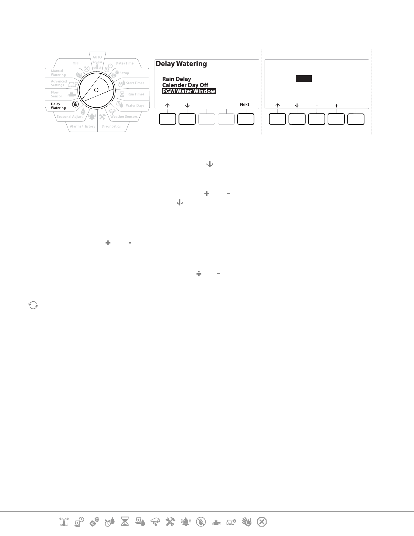
Current Section: Delay Watering 56
Navigation:
12.4.4 Water Window Set Up
Delay Watering
Next
Rain Delay
Calender Day Off
PGM Water Window
Water Window
PGM 01
Done
Open:
Close:
Duration:
06:00
08:15
02:15
HH:MM
1 Turn the controller dial to Delay Watering
2 At the Delay Watering screen, press the
key to select “PGM Water Window”, then press Next
.
3 At the Water Window screen, press the and keys to set the time when the Watering
Window opens, then press the key.
•
Press and HOLD keys to accelerate settings.
4 Press the and keys to set the time when the Watering Window closes. As you adjust
the close time, the duration of your Water Window calculates automatically.
•
To clear a previously set Water Window, press the and keys to set both the Open and Close times to OFF
(between 11:59 and 12:00 AM).
Use the Program Select button to set the Water Window for another program, if desired.

Current Section: Flow Sensor 57
Navigation:
13. FLOW SENSOR
13.4.1 Introduction to Flow
The LXME2 controller oers a wide variety of ow-related functionality to utilize your system more
eciently, with or without additional ow sensing hardware.
•
See here for examples of ow sensor installations.
13.4.2 FloZones Overview
The FloZone is the group of stations connected to the Master Valve. The LXME2 supports 1 FloZone.
Non Irrigation Stations are not part of the FloZone.
13.4.3 Flow Management Features
After setting the Master Valves and FloZones for your system, the next step is to decide which ow-
related features you’d like to use.
The LXME2 controller ow features can be divided into two dierent functional groups; Flo-
Manager® and FloWatch.
Flo-Manager®
Flo-Manager® adds basic hydraulic management features to your system to ensure that sucient
water pressure and volume is available to operate all stations.
•
Although it is helpful, ow sensing hardware is not required to use Flo-Manager®. You can manually enter
estimated ow rates even if ow sensing hardware is not installed.
Flo-Watch™
FloWatch allows you to use any or all of the Flo-Manager® features but adds additional functionality
such as alarms for high ow and low ow situations based on parameters you set and control. See
“Set Flow Limits” for more details.
•
Flow sensing hardware is required to use FloWatch.
13.1 Flow Sensors
This menu item is the same as Setup - Flow Sensors. If you have already set up a ow sensor then it
should appear here.
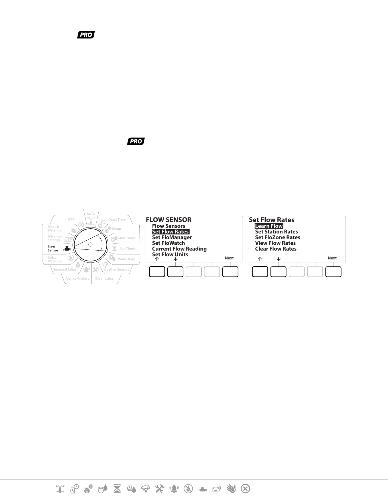
Current Section: Flow Sensor 58
Navigation:
Learn Flow - Models only
The LXME2 controller lets you set the ow rates you expect or to automatically Learn Flow rates
based on real usage.
If you do not have ow sensing hardware installed you may be able to estimate ow rates based
on the irrigation hardware installed on a particular station or FloZone and manually enter this rate.
FloZone ow rates are either:
• Automatically set to the highest station ow rate assigned to the FloZone, or
• Manually adjusted by the user.
Learn Flow Automatically - Models only
•
To ensure accurate recording of ow rates, do not create any manually-generated ow such as ow created
with manually operated quick coupling valves, while a Learn Flow is taking place.
All Stations
FLOW SENSOR
Next
Flow Sensors
Set Flow Rates
Set FloManager
Set FloWatch
Current Flow Reading
Set Flow Units
Set Flow Rates
Next
Learn Flow
Set Station Rates
Set FloZone Rates
View Flow Rates
Clear Flow Rates
•
Ensure you have Run Times set up for all stations included in a Learn Flow exercise prior to setting up a Learn
Flow.
1 Turn the controller dial to Flow Sensor
2 At the FLOW SENSOR screen, with “Set Flow Rates” selected, press Next .
3 At the Set Flow Rates screen, with “Learn Flow” selected, press Next .
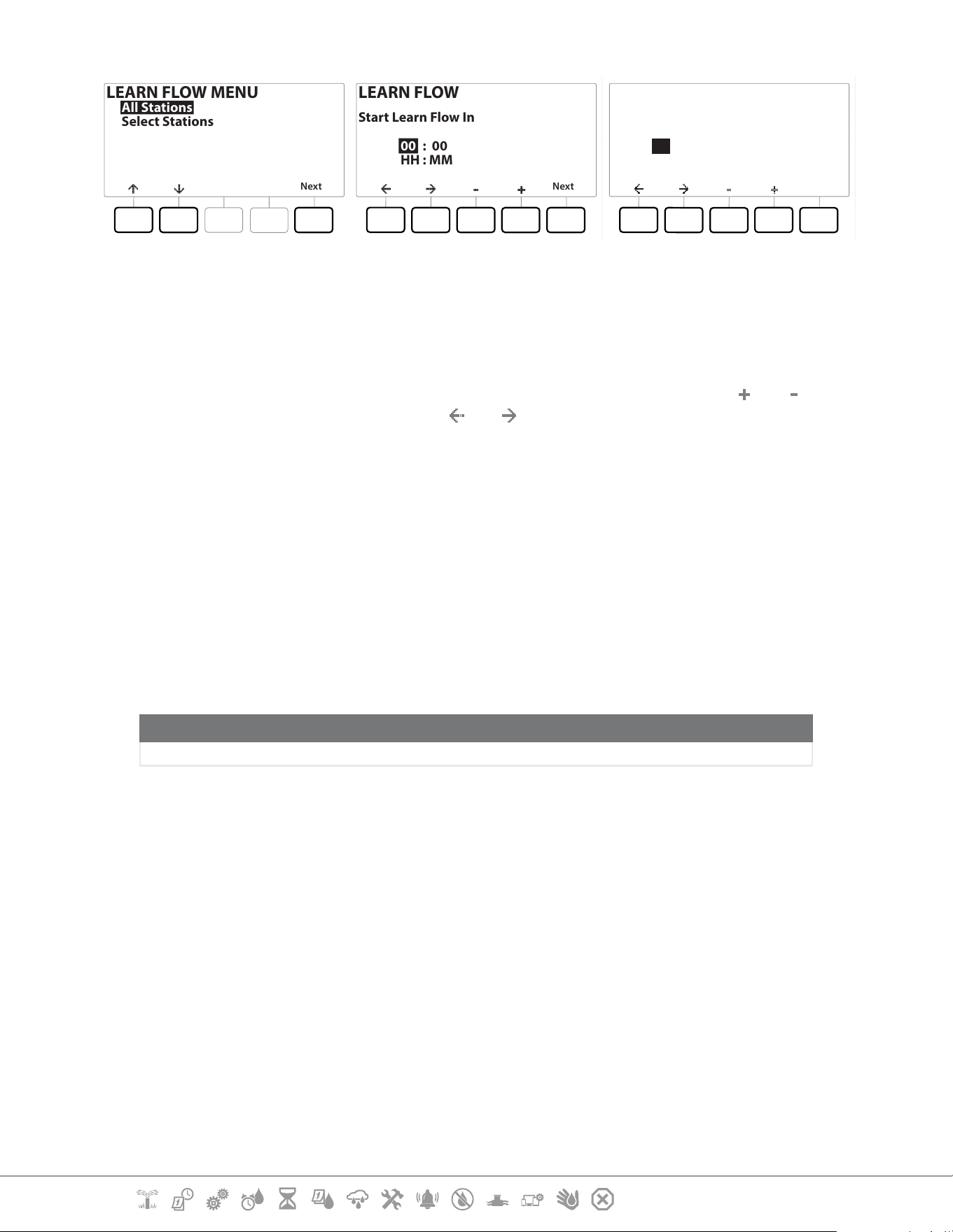
Current Section: Flow Sensor 59
Navigation:
LEARN FLOW MENU
Next
All Stations
Select Stations
LEARN FLOW
Next
00 : 00
HH : MM
Start Learn Flow In
LEARN FLOW
Next
06 : 00
HH : MM
Start Learn Flow In
4 At the LEARN FLOW MENU screen, with “All Stations” selected, press Next .
5 A conrmation screen appears; press Next again.
6 An information screen appears; press Next again.
7 To start the Learn Flow exercise immediately, press Next . Or else press the
and keys
to set a delayed start time. Press the
and to navigate between the number setting
elds.
•
You can choose to run the exercise Now (00:00) or choose a timed delay of up to 24 hours.
8 A conrmation screen appears, conrming the Learn Flow will overwrite the existing
ow rates. Press Start to set the Learn Flow exercise.
9 The Learn Flow Starting conrmation screen shows the time delay until the Learn Flow
operation will start.
•
An alarm will be posted if one or more stations learn a ow rate of 0 (zero). Check the valve if you receive this
alarm.
NOTICE
Be sure to Learn Flow again if you make any changes to your system which aect its hydraulics.
13.1.1 Selected Stations
•
Ensure you have Run Times set up for all stations included in a Learn Flow exercise prior to setting up a Learn
Flow.
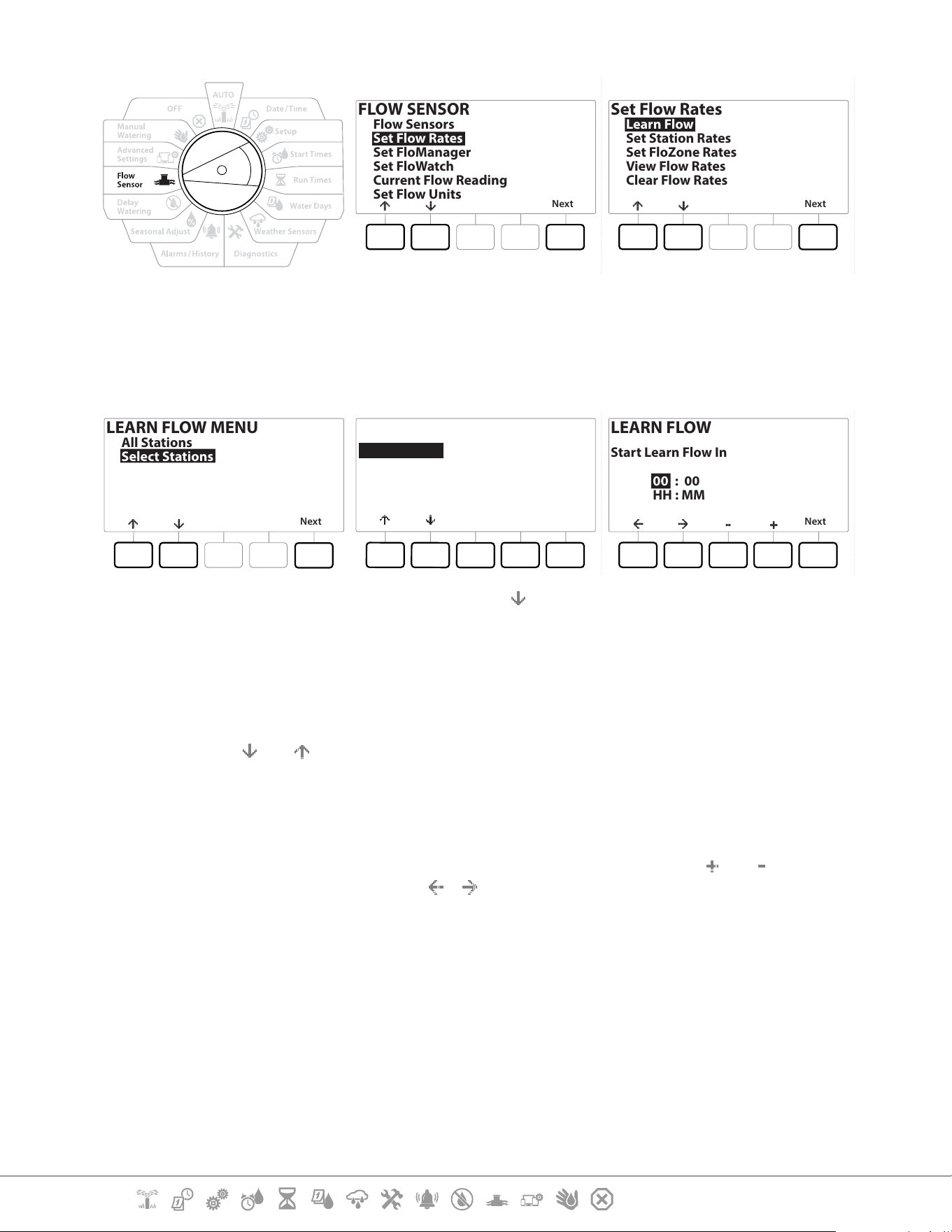
Current Section: Flow Sensor 60
Navigation:
FLOW SENSOR
Next
Flow Sensors
Set Flow Rates
Set FloManager
Set FloWatch
Current Flow Reading
Set Flow Units
Set Flow Rates
Next
Learn Flow
Set Station Rates
Set FloZone Rates
View Flow Rates
Clear Flow Rates
1 Turn the controller dial to Flow Sensor
2 At the FLOW SENSOR screen, with “Set Flow Rates” selected, press Next .
3 At the Set Flow Rates screen, with “Learn Flow” selected, press Next .
LEARN FLOW MENU
Next
All Stations
Select Stations
Include in Learn Flow
Next
Sta001 Ye s
Sta002 Ye s
Sta003 Ye s
Sta004 No
Yes No
LEARN FLOW
Next
00 : 00
HH : MM
Start Learn Flow In
5 At the LEARN FLOW MENU screen, press the key to select “Select Stations”, then press
Next.
6 A conrmation screen appears; press Next again.
7 An information screen appears; press Next again.
8 Press the and to navigate the list of stations. Press the Yes and No keys to set which
stations you want to include in the Learn Flow exercise, then press Next to continue.
•
You can choose to run the exercise Now (00:00) or choose a timed delay of up to 24 hours.
9 To start the Learn Flow exercise immediately, press Next . Or press the and keys to
set a delayed start time. Press the
& keys to navigate between the number setting
elds.
10 A conrmation screen appears, conrming the Learn Flow will overwrite the existing
ow rates. Press “Start” to set the Learn Flow exercise.
11 The Learn Flow Starting conrmation screen appears, conrming the time delay until
the Learn Flow operation will start.
•
An alarm will be posted if one or more stations learn a ow rate of 0 (zero).
•
Be sure to Learn Flow again if you make any changes to your system which aect its hydraulics.
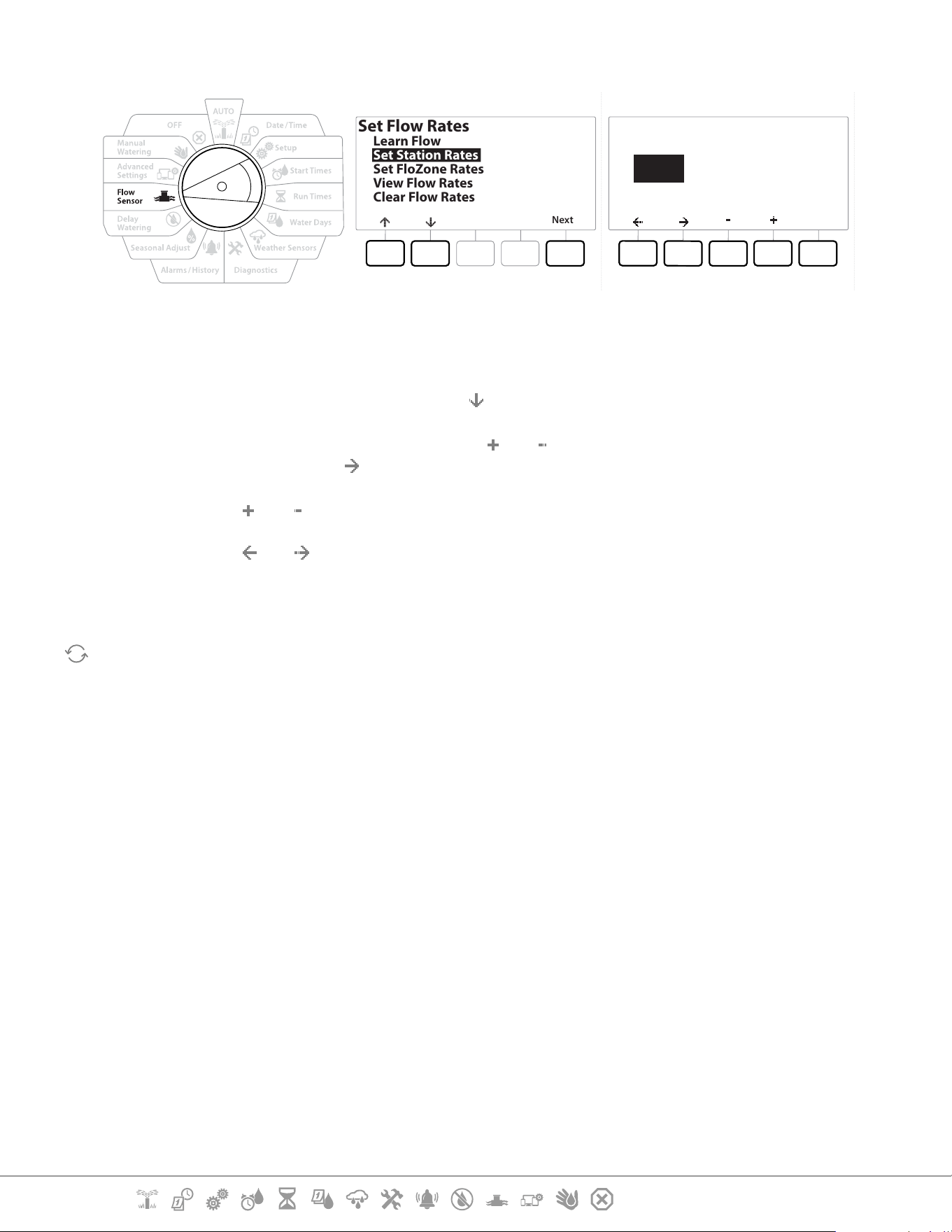
Current Section: Flow Sensor 61
Navigation:
13.1.2 Set Station Rates
Set Flow Rates
Next
Learn Flow
Set Station Rates
Set FloZone Rates
View Flow Rates
Clear Flow Rates
Done
Set Station Rates
001 0000.0
User Entered
Station
FZ None
GPM
1 Turn the controller dial to Flow Sensor
2 At the FLOW SENSOR screen, with “Set Flow Rates” selected, press Next .
3 At the Set Flow Rates screen, press the key to select “Set Station Rates”, then press Next .
4 At the Set Station Rates screen, press the and keys to set the desired Station (from 1
to 240), then press the key.
5 Press the and keys to set the desired Flow Rate for that station.
6 Press the and to navigate between the number setting elds.
•
Press and HOLD keys to accelerate settings.
Repeat this process to manually set up Flow Rates for additional stations as desired.
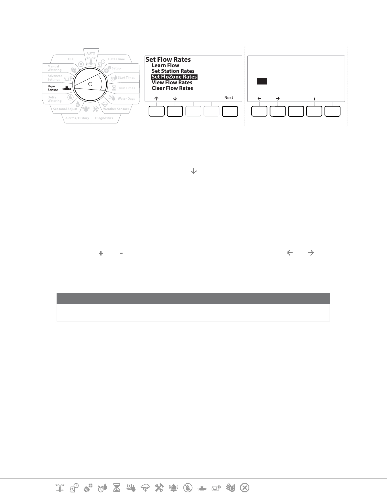
Current Section: Flow Sensor 62
Navigation:
13.1.3 Set FloZone Rates
Set Flow Rates
Next
Learn Flow
Set Station Rates
Set FloZone Rates
View Flow Rates
Clear Flow Rates
Set FloZone Rates
Done
FloZone
001
Max GPM
2000.0
Do not set rate
below 0000.0
MV(s) 1
FS (s) 1
1 Turn the controller dial to Flow Sensor
2 At the FLOW SENSOR screen, with “Set Flow Rates” selected, press Next .
3 At the Set Flow Rates screen, press the
key to select Set FloZone Rates, then press
Next .
4 The Set FloZone Rates information screen appears; press Next .
•
The LXME2 features one FloZone.
5 Press the right arrow key to navigate to the MAX GPM eld.
6 Press the
and keys to set the Max GPM for that FloZone. Press the and to
navigate between the number setting elds.
•
Press and HOLD keys to accelerate settings.
NOTICE
Maximum FloZone ow rates are used only by Flo-Manager®. FloWatch is unaected by user-entered
FloZone ow rates.
7 After Flo-Manager® is enabled and station and/or FloZone ow rates are entered, Flo-
Manager® works automatically in the background to run stations based on available
hydraulic capacity.
•
Flo-Manager® can be used with or without ow sensing hardware. If ow sensors are not present it will rely
on manually entered information; if ow sensors are present it will rely on Learned Flow information, which
is typically more accurate.
13.1.4 View Flow Rates
Occasionally you may want to view user entered or learned ow rates and their source for a station
or FloZone.
•
View Flow Rates does not show actual live ow rates but the expected or learned ow rates by station or
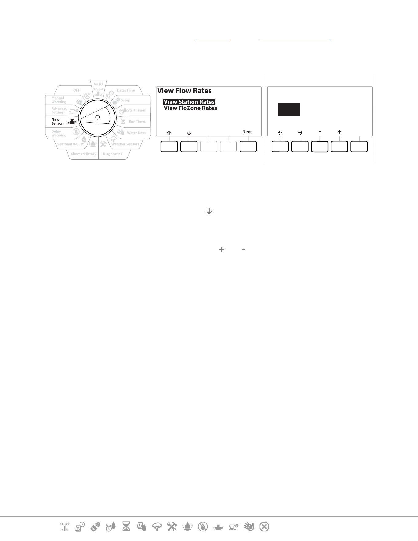
Current Section: Flow Sensor 63
Navigation:
FloZone. You can view live ow rates if you have FloWatch™ setup see Current Flow Reading.
View Station Rates
View Flow Rates
Next
View Station Rates
View FloZone Rates
Done
View Station Rates
001 0000.0
User Entered
Station
FZ None
GPM
1 Turn the controller dial to Flow Sensor
2 At the FLOW SENSOR screen, with “Set Flow Rates” selected, press Next .
3 At the Set Flow Rates screen, press the key to select “View Flow Rates”, then press Next .
4 The View Flow Rates screen appears with “View Station Rates” selected; press Next.
5 At the View Station Rates screen, press the and keys to set the desired station
number. The FloZone for each station is shown below it. The normal ow rate for each
station will show to the right, and the source of the ow rate (Learned or User Entered)
shows below it.
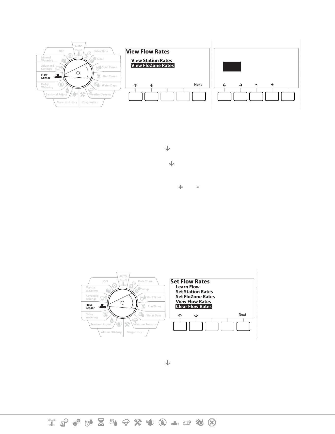
Current Section: Flow Sensor 64
Navigation:
13.1.5 View FloZone Rates
View Flow Rates
Next
View Station Rates
View FloZone Rates
Done
View FloZone Rates
001 0000.0
FloZone
Max GPM
MV(s) 1
FS (s) 1
1 Turn the controller dial to Flow Sensor
2 At the FLOW SENSOR screen, with “Set Flow Rates” selected, press Next .
3 At the Set Flow Rates screen, press the
key to select “View Flow Rates”, then press Next.
4 At the View Flow Rates screen, press the
key to select “View FloZone Rates”, then press
Next .
5 At the FloZone Flow Rates screen, press the
and keys to select the desired FloZone
number. The MVs and sensors associated with that ow zone are shown below it. The
maximum ow rate for that FloZone will show to the right.
•
FloZone rates are used by FloManager. The zone rate cannot be set lower than the highest station rate.
13.1.6 Clear Flow Rates
Occasionally it may be desired to clear the previously learned or user entered ow rates and start
over.
Set Flow Rates
Next
Learn Flow
Set Station Rates
Set FloZone Rates
View Flow Rates
Clear Flow Rates
1 At the FLOW SENSOR screen, with “Set Flow Rates” selected, press Next .
2 At the Set Flow Rates screen, press the
key to select “Clear Flow Rates”, then press Next.
3 The conrmation screen appears; press Next to clear ow rates.
4 A conrmation screen shows the process is complete.

Current Section: Flow Sensor 65
Navigation:
13.1.7 Set Flo-Manager®
One of the most powerful ow management features in the LXME2 controller is Flo-Manager®.
Flo-Manager® enables the controller to allocate available water capacity to various stations based on
their hydraulic requirements.
This can be done even if ow sensors are not present.
Flo-Manager® works by adding another layer of station or system (FloZone) prioritization based on
available water resources. For example, if the FloZone has 20 GPM available ow and two stations
each consuming 6 GPM are currently in operation for a total of 12 GPM, FloManager® Will not allow
an additional station to start unless it consumes 8 GPM or less. This helps ensure that your system’s
hydraulic resources are not overtaxed and that sucient water is available to every sprinkler in every
station.
13.1.8 Flo-Manager® Set Up
•
If you have not already done so, use the Setup dial position to set up all master valves and the FloZone. See
“Master Valves” or more details.
It’s not necessary to install or set up ow sensors to use Flo-Manager®, but if you do have this
hardware present it’s usually helpful to set it up prior to activating Flo-Manager®. See “Flow Sensors”
for more details.
Once Flo-Manager® has been activated we recommend that you Learn Flow or manually enter ow
rates for all stations and for the entire FloZone. This will allow Flo-Manager® to dynamically allocate
water resources.
If you do not have ow sensing hardware installed you may be able to estimate ow rates based on
the irrigation hardware installed on a particular station or the entire FloZone and manually enter this
rate.
13.1.9 Enable or Disable Flo-Manager®
1 Turn the controller dial to Flow Sensor
2 At the FLOW SENSOR screen, press the
key to select Set Flo-Manager®, then press Next
3 At the Flo-Manager® screen, press the On key to turn on FloManager®
The conrmation screen appears. Press Accept to turn on FloManager.
•
Turning on Flo-Manager® changes Station Sequencing to Station Priorities. If you’re not sure about it press
the Reject key.
13.1.10 Set FloWatch™
FloWatch unleashes the true power of the LXME2 controller.

Current Section: Flow Sensor 66
Navigation:
FloWatch compares current ow conditions to expected, learned or user-entered ow rates and
takes various actions based on your settings and input. Since current ow conditions are required,
FloWatch can only be used when ow sensors are present. To use FloWatch, you must do all of the
following:
1 Install ow monitoring hardware into the appropriate locations of your irrigation
system. You should install one ow sensor just downstream of each master valve but
upstream of any station valves.
•
Note: To ensure stable readings make sure you follow the manufacturer’s instructions when you install the
ow sensor.
2 Connect the ow sensor to the Pro Smart module, for more details, see “Connect a Flow
Sensor
3 Set up the ow sensors using the ow sensor setup. See “Flow Sensors” for more details.
4 Follow the directions below to set up FloWatch.
•
Once you have set up FloWatch on the controller, the current ow rate will be shown on the Auto screen
unless you turn o FloWatch™.
13.1.11 FloWatch™ Set Up
The LXME2 controller lets you set the ow rates you expect or to automatically Learn Flow rates
based on real usage.
Once ow is learned or manually entered, the High Flow and Low Flow settings let you dene the
parameters for excessive or low ow and to set the behavior of the controller when these conditions
are detected. You can also turn FloWatch o or back on again if you like.
FloWatch needs expected ow rates to work properly. Flow rates can be entered manually or can
be learned automatically through a Learn Flow process. An automatic Learn Flow operation will
Learn Flow for each station that has programmed Run Times. Ensure you have set up run times for all
stations included in a Learn Flow exercise prior to setting up a Learn Flow.
•
Prior to learning or manually setting station ow rates, it is a good idea to check the Master Valve
assignments for each of your stations. See “Station Setup” for more details.
NOTICE
Water pressure, particularly from municipal sources, can vary signicantly throughout the day. To mitigate
this variance, press the time delay option to delay the Learn Flow start time to when irrigation would
normally operate.

Current Section: Flow Sensor 67
Navigation:
13.1.12 FloWatch™ On/O
1 Turn the controller dial to Flow Sensor
2 At the FLOW SENSOR screen, press the key to select “Set FloWatch”, then press Next .
3 At the FloWatch screen, with “FloWatch On/Off” selected press Next .
4 Press the On key to turn on FloWatch, or else press O to disable.
•
Once FloWatch is enabled we recommend that you Learn Flow or manually enter ow for all stations and
FloZones if you have not already done so. This will allow FloWatch to react appropriately to the High Flow
and Low Flow settings.
13.1.13 Set Flow Limits
SEEF: seek and eliminate excessive ow (High Flow)
SELF: seek and eliminate excessive ow (Low Flow)
To most eectively use FloWatch™, you will want to rst set your High Flow and Low Flow thresholds
and actions. SEEF (High Flow) stands for Seek and Eliminate Excessive Flow and deals with how
you want the controller to respond when excessive ow is occurring, as might be the case with a
mainline break or a valve which is stuck in the open position. SELF (Low Flow) stands for Seek and
Eliminate Low Flow and deals with what the controller should do when low ow is present, as might
be the case during a pump failure, municipal water supply issue or when a valve fails to open.
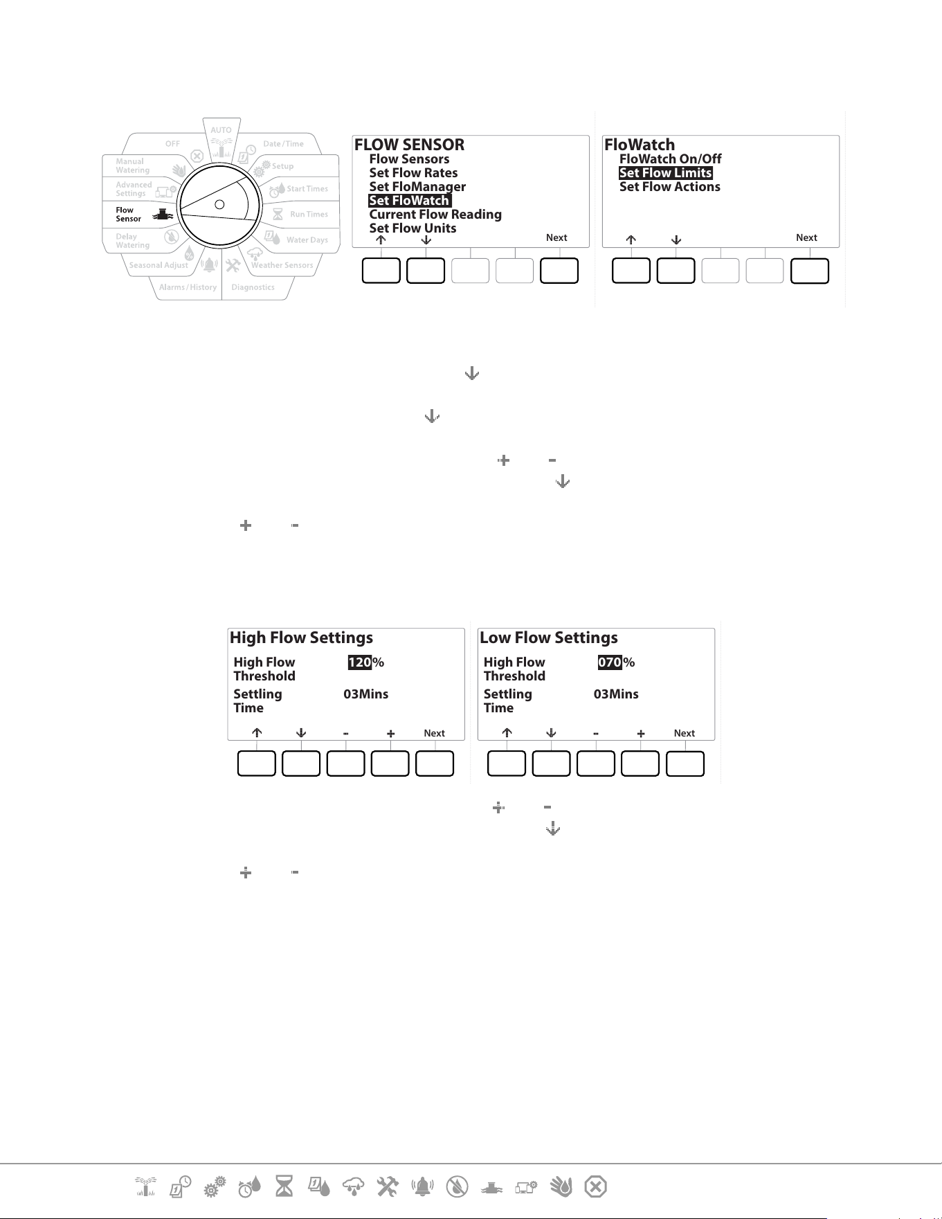
Current Section: Flow Sensor 68
Navigation:
13.1.14 Set Up and Congure High Flow and Low Flow
FLOW SENSOR
Next
Flow Sensors
Set Flow Rates
Set FloManager
Set FloWatch
Current Flow Reading
Set Flow Units
FloWatch
Next
FloWatch On/Off
Set Flow Limits
Set Flow Actions
1 Turn the controller dial to Flow Sensor
2 At the FLOW SENSOR screen, press the key to select “Set FloWatch”, then press Next .
3 At the FloWatch screen, press the
key to select “Set Flow Limits”, then press Next .
4 At the High Flow Settings screen, press the
and keys to set the desired High Flow
Threshold percentage (Max. 200%). Then press the
key.
5 Press the and keys to set the desired High Flow settling time (Up to 10 minutes ),
then press Next .
•
Press and HOLD keys to accelerate settings.
High Flow Settings
Next
High Flow
Threshold
120%
Settling
Time
03Mins
Low Flow Settings
Next
High Flow
Threshold
070%
Settling
Time
03Mins
6 At the Low Flow Settings screen, press the and keys to set the desired Low Flow
Threshold percentage (Max. 95%). Then press the key.
7 Press the and keys to set the desired Low Flow settling time (Up to 10 minutes ).
•
Press and HOLD keys to accelerate settings.

Current Section: Flow Sensor 69
Navigation:
13.1.15 Set Flow Actions
There are 3 options available to Set Flow Actions during High or Low ow:
• Diagnose & Eliminate
• Shut Down & Alarm
• Alarm Only
1 Turn the controller dial to Flow Sensor
2 At the FLOW SENSOR screen, press the
key to select “Set FloWatch”, then press Next .
3 At the FloWatch screen, press the key to select “Set Flow Actions”, then press Next .
4 At the Action Under High Flow screen, press the and keys to set the desired option
to occur under High Flow, then press Next
5 At the Action Under Low Flow screen, press the and keys to set the desired option
to occur under Low Flow, then press Next
6 At the Re-enable time screen, press the and keys to set the desired number for
hours (from 0 to 23). Press the Arrow keys to navigate between the number setting
elds. Set the minutes (from 0 to 59).
13.1.16 Current Flow Reading
Occasionally it may be useful to check the current ow rate in a particular FloZone and how that
compares to previously learned or user input station ow rates.
1 Turn the controller dial to Flow Sensor
2 At the FLOW SENSOR screen, press the key to select “Set Current Flow Reading”, then
press Next .
3 At the View Current Flow screen, press the and keys to select the desired FloZone
number. Current and expected ow will show.
•
Expected ow is from previously user-entered or learned station ow rates. The deviation or percentage
comparison of current ow to expected ow will show so you can see how close each FloZone is to a High
Flow or Low Flow condition (see Setting Up High Flow and Low Flow for more details).

Current Section: Flow Sensor 70
Navigation:
13.1.17 Set Flow Units
To use Flo-Manager® or FloWatch™ with the LXME2 controller, you rst need to set the measurement
units for ow management.
1 Turn the controller dial to Flow Sensor
2 At the FLOW SENSOR screen, press the
key to select “Set Flow Units”, then press Next .
3 At the Set Flow Units screen, press the
and keys to set the desired ow rate (M3/Hr,
Auto, GPM, LPS, or LPM). Then navigate to the Pipe size selection by pressing the key.
4 Press the
and keys to set the desired pipe size measurement (Auto, Inch, or mm).
•
If Auto is selected, Flow Rate will default to GPM when 60 Hz is detected and to LPS when 50 Hz is detected.
Pipe Size will default to Inches on 60 Hz and to millimetres on 50 Hz.
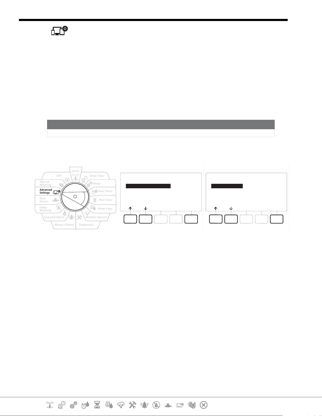
Current Section: Advanced Settings 71
Navigation:
14. ADVANCED SETTINGS
14.1.1 Store/ Recall Programs
The LXME2 controller comes standard with a simple to use backup programs feature.
Backup Programs allows you to save your programs as Contractor Default and then recall them at
a later time. It also includes a Delayed Recall feature that lets you save a normal irrigation schedule
as the Backup and then restore it later automatically. This may be useful for new seed or sod where
frequent irrigation can be programmed to occur until a set date when Delayed Recall automatically
returns the controller programming to the normal irrigation schedule.
NOTICE
The Backup Programs feature saves and restores ALL irrigation programming in ALL programs.
Store Programs
IQ / ADVANCED
Next
Store/Recall Programs
Factory Defaults
Configure Cartridge
About this LX-ME2
Program Options
Next
Store Programs
Recall Programs
Delayed Recall
Clear Programs
1 Turn the controller dial to Advanced Settings
2 At the IQ / ADVANCED screen, with “Store/Recall Programs” selected, press Next.
3 At the Program Options screen, with “Store Programs” selected, press Next.
4 At the conrmation screen, press and HOLD the Yes key for 4 seconds to Store All
Programs. If you’re not sure, press No.
5 A conrmation screen shows the process is running.
6 A conrmation screen shows the process is complete.
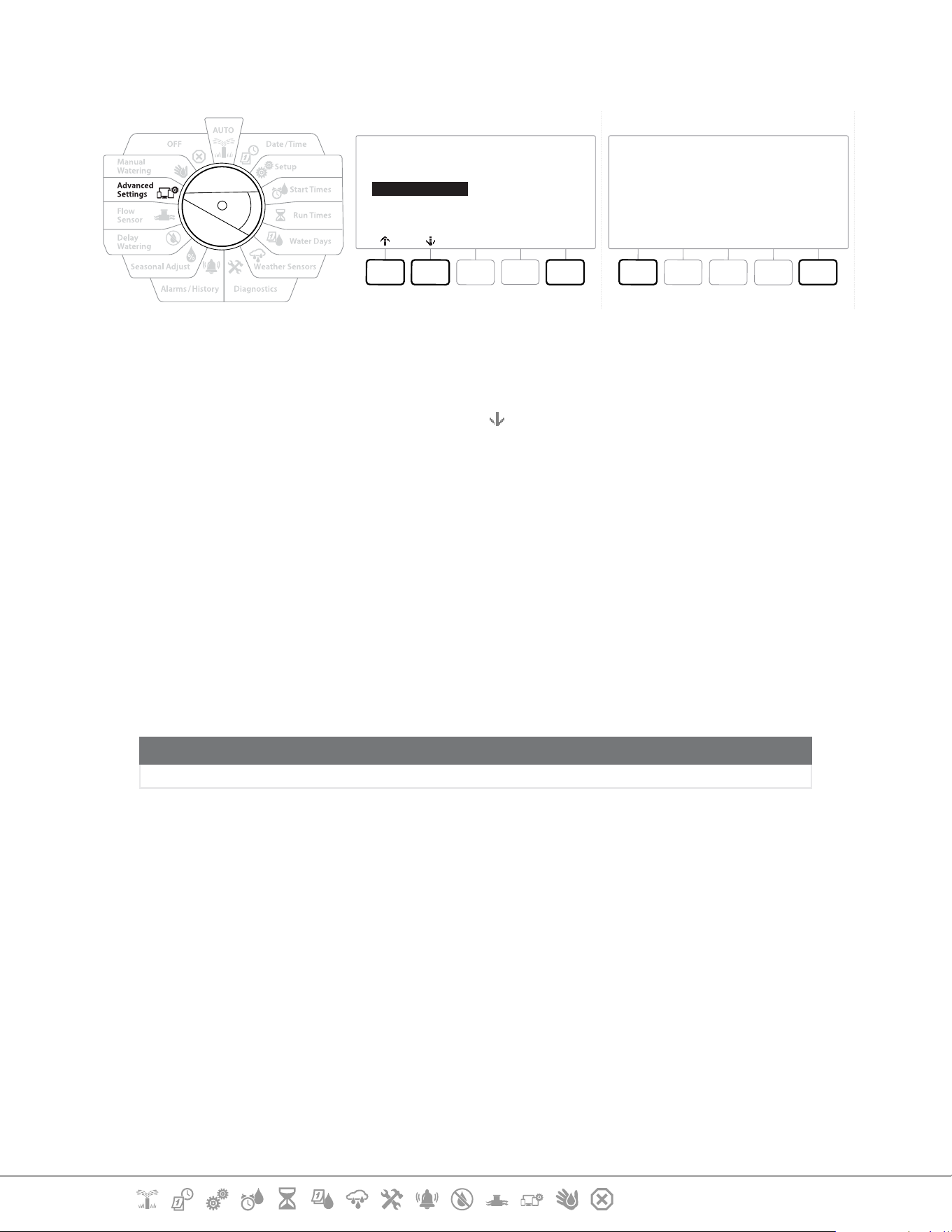
Current Section: Advanced Settings 72
Navigation:
Recall Programs
Program Options
Next
Store Programs
Recall Programs
Delayed Recall
Clear Programs
Recall All Programs
NoYes
Are you sure? Press and hold
Yes to proceed.
1 Turn the controller dial to Advanced Settings
2 At the IQ / ADVANCED screen, with “Store/Recall Programs” selected, press Next .
3 At the Program Options screen, press the key to select “Recall Programs”, then press
Next.
4 At the conrmation screen, press and HOLD the Yes key for 4 seconds to Recall All
Programs. If you’re not sure, press No.
5 A conrmation screen shows the process is running.
6 A conrmation screen shows the process is complete.
Delayed Recall Programs
Use the Delayed Recall feature to automatically replace the currently loaded programs with a
previously stored program at a future date.
NOTICE
Once current programs have been replaced with the Delayed Recall feature, they can not be restored.
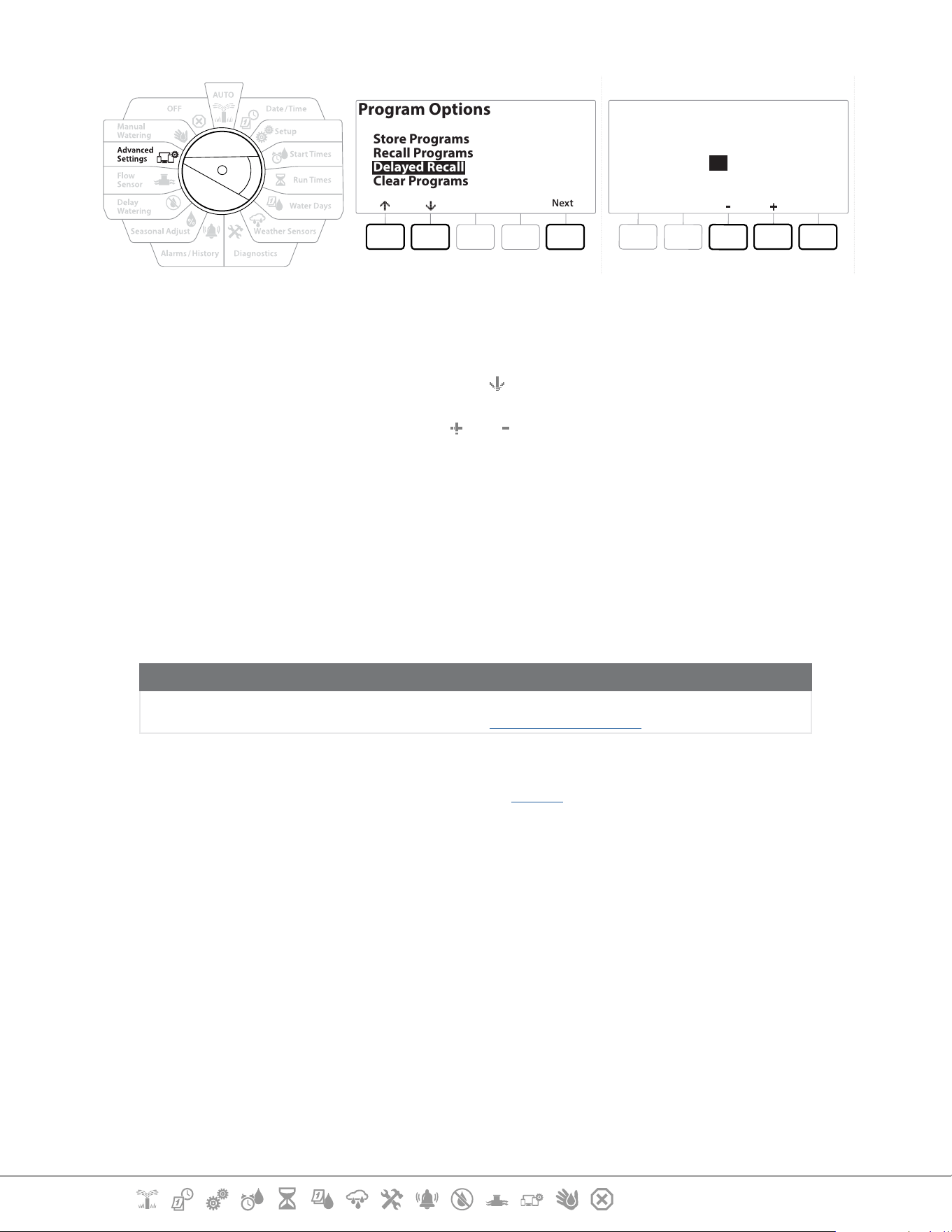
Current Section: Advanced Settings 73
Navigation:
Program Options
Next
Store Programs
Recall Programs
Delayed Recall
Clear Programs
Recall Delay
Next
02
Days Remaining
1 Turn the controller dial to Advanced Settings
2 At the IQ / ADVANCED screen, with “Store/Recall Programs” selected, press Next .
3 At the Program Options screen, press the key to select “Delayed Recall”, then press Next.
4 At the Recall Delay screen, press the
and keys to set the number of days (from 0 to
90 days) before Contractor Defaults are restored. For example, set it to 7 days if you want
your original programs to be restored in one week.
•
To clear a Delayed Recall, set the number of days to 0.
Clear Program Information
The LXME2 controller allows you to clear an individual Program, all of your Programs or Restore the
controller to it’s factory default condition.
NOTICE
It’s recommended to back up your Programs before clearing them. The LXME2 controller’s built in Store
Programs feature can backup one set of programs. See “Store/ Recall Programs” for more details.
•
Irrigation start days, Start Times and station Run Times will no longer be present for the cleared Programs. If
no Programming exists then an Alarm will be shown. See “Alarms” for more details.
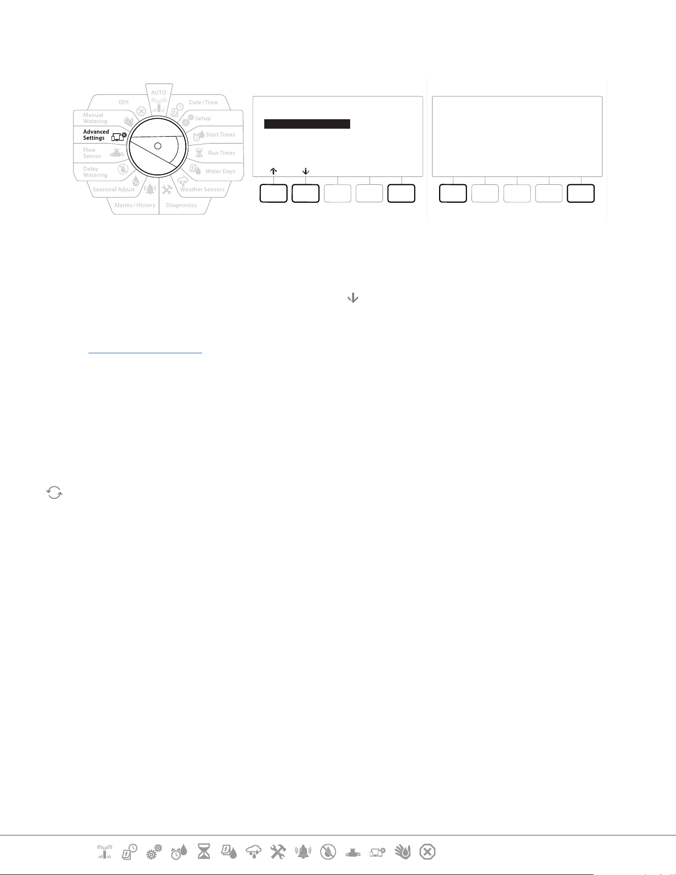
Current Section: Advanced Settings 74
Navigation:
Clear Individual Program
Clear Programs
Next
Individual Programs
All Programs
Clear PGM 01
NoYes
Are you sure? Press and hold
Yes to proceed.
1 Turn the controller dial to Advanced Settings
2 At the IQ / ADVANCED screen, with “Store/Recall Programs” selected, press Next .
3 At the Program Options screen, press the key to select “Clear Programs”, then press Next .
•
If the desired program is not selected, press the Program Select button to choose the desired program. See
“Program Select Button” for more details.
4 At the Clear Programs screen with “Individual Programs” selected; press Next .
5 At the conrmation screen, press and HOLD the Yes key for 4 seconds to Clear Programs.
If you’re not sure, press No.
6 A conrmation screen shows the process is complete.
Use the Program Select button to change the current program and repeat this process to clear other
programs.
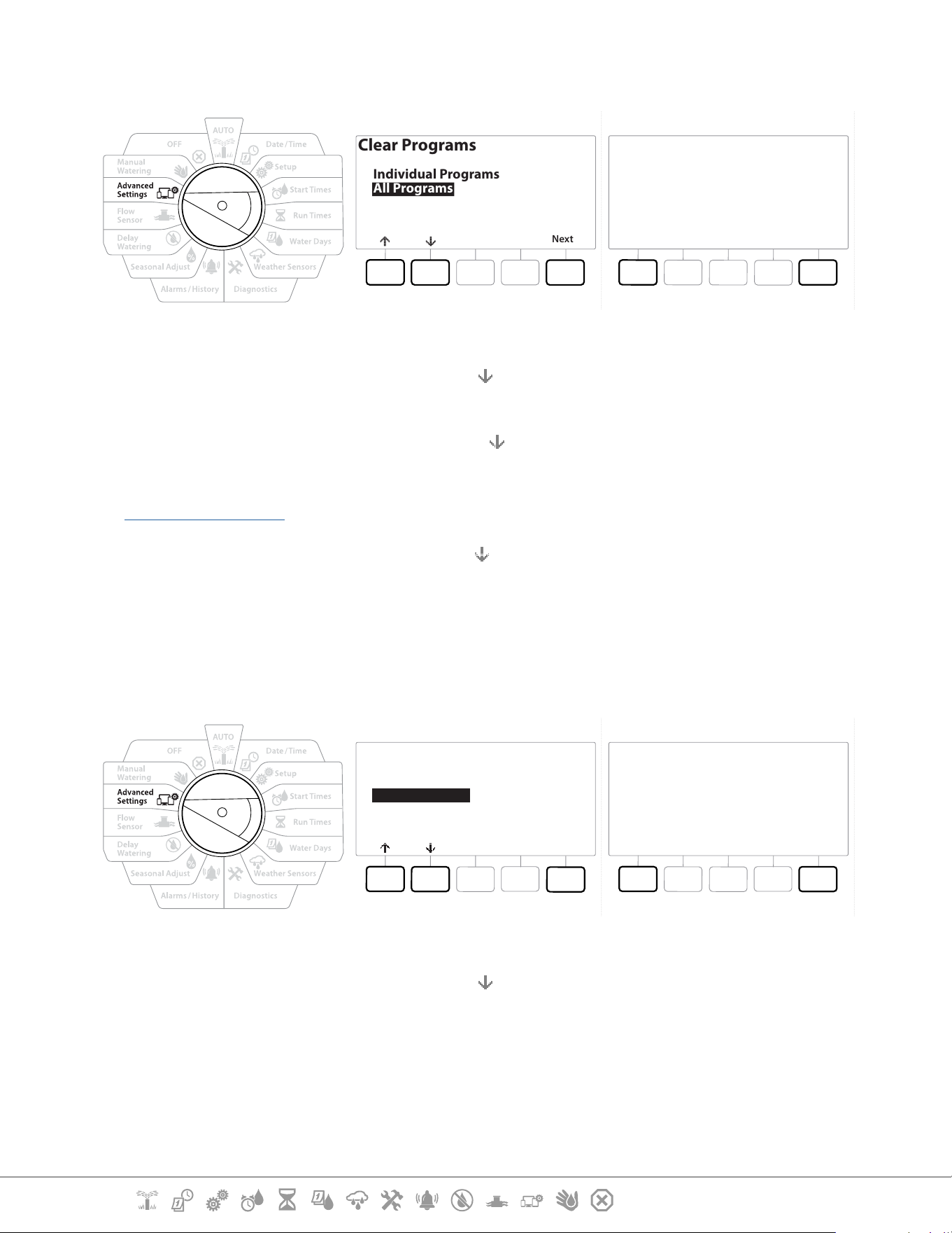
Current Section: Advanced Settings 75
Navigation:
Clear All Programs
Clear Programs
Next
Individual Programs
All Programs
Clear All Programs
NoYes
Are you sure? Press and hold
Yes to proceed.
1 Turn the controller dial to Advanced Settings
2 At the IQ / ADVANCED screen, press the key to select “Store/Recall Programs”, then press
Next .
3 At the Program Options screen, press the key to select “Clear Programs”, then press Next.
•
If the desired program is not selected, press the Program Select button to choose the desired program. See
“Program Select Button” for more details.
4 At the Clear Programs screen, press the key to select “All Programs”, then press Next .
5 A conrmation screen shows the process is complete.
14.1.2 Factory Defaults
Restore the LXME2 controller’s factory default settings.
IQ / ADVANCED
Next
Store/Recall Programs
Factory Defaults
Configure Cartridge
About this LX-ME2
Restore Factory Default
NoYes
Are you sure? Press and hold
Yes to proceed.
1 Turn the controller dial to Advanced Settings
2 At the IQ / ADVANCED screen, press the
key to select “Factory Defaults”, then press Next.
3 At the conrmation screen, press and HOLD the Yes key for 4 seconds to Restore Factory
Defaults. If you’re not sure, press No.
4 A conrmation screen shows the process is complete.
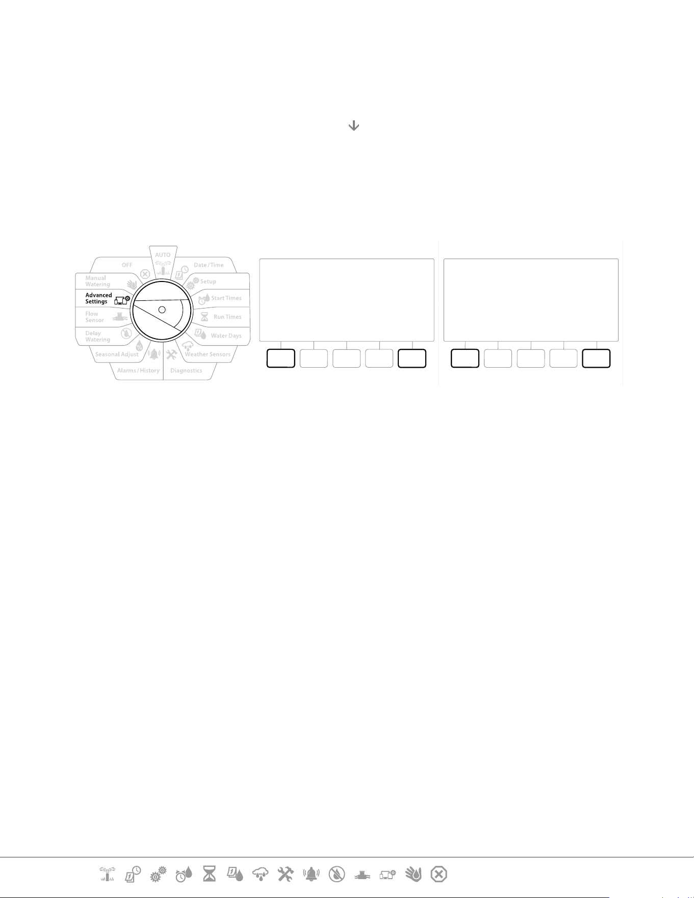
Current Section: Advanced Settings 76
Navigation:
14.1.3 About this LXME2
1 Turn the controller dial to Advanced Settings
2 At the IQ / ADVANCED screen, press the
key to select “About this LXME2”, then press
Next.
3 The ABOUT LXME2 screen appears with an overview of your LXME2 including the
information of the version, front panel and cartridge
4 Press the More button for an overview of the slots of your LXME2.
ABOUT LXME2
DoneMore
Firmware Versions
Front Panel: 1.90.0
Cartridge: None
ABOUT LXME2
DoneMore
Firmware Versions
Slot 1: 0.16
Slot 2: 0.16
Slot 3: 0.16
Slot 4: None
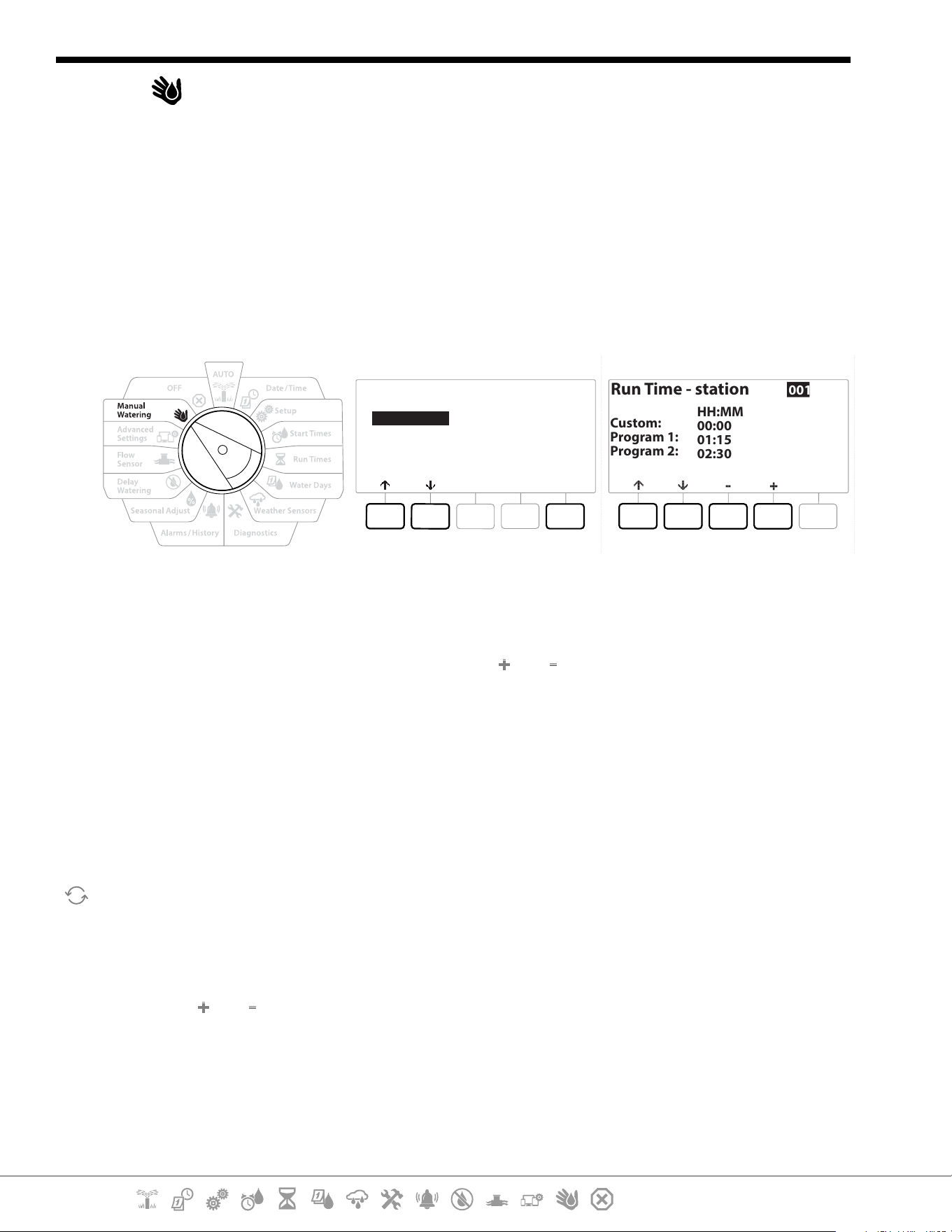
Current Section: Manual Watering 77
Navigation:
15. MANUAL WATERING
The LXME2 controller allows you to manually start a station, a program, or to open a Normally Closed
Master Valve (NCMV) to provide water to a for manual watering.
15.1.1 Start Station
•
Manual Watering > Start Station will pause currently running programs.
•
Ensure device addresses are present and entered correctly prior to Manual Station or Manual Program
operations.
Manual Watering
Next
Start Station
Start Program
MV Water Window
Test All Stations
Run Time - station
Custom:
Program 1:
Program 2:
HH:MM
00:00
01:15
02:30
001
1 Turn the controller dial to Manual Watering
2 At the Manual Watering screen, with “Start Station” selected, press Next .
3 At the Run Time - Station screen, press the and key to select the desired station
(from 1 to 240) to run manually.
4 Press the Arrow keys to set the station Run Time (from 0 hours, 1 minute to 96 hours).
Press the Run key to start irrigation for that station.
•
Press and HOLD keys to accelerate settings.
5 A conrmation screen shoes that irrigation has started.
Repeat this process to manually water other stations
•
Stations will run sequentially in the order in which they were selected.
6 To view the Station while running, turn the controller dial to the AUTO position. Press
the and keys to add or subtract minutes from the run time for the currently running
station. To advance to the Next station in a program, press the Adv key.
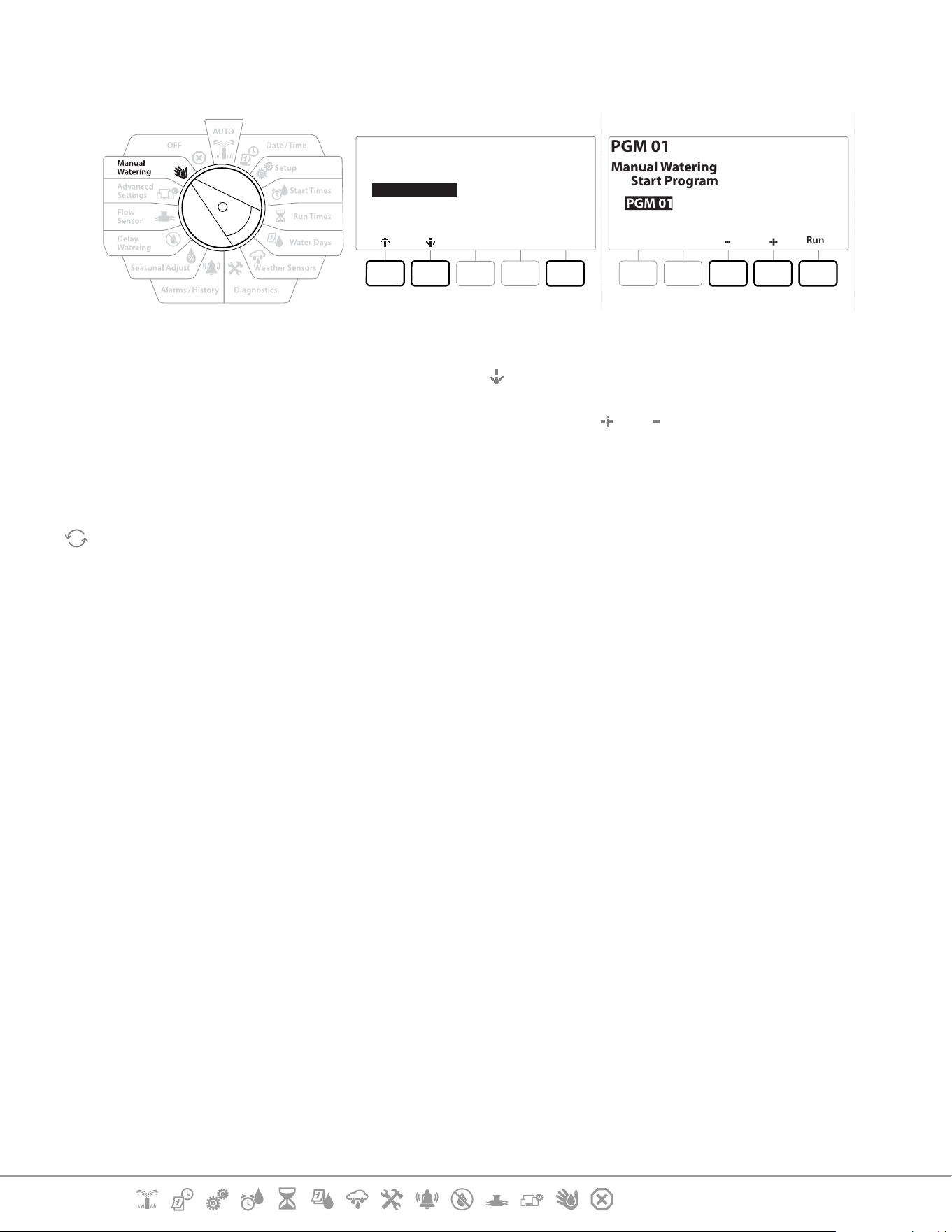
Current Section: Manual Watering 78
Navigation:
15.1.2 Start Program
Manual Watering
Next
Start Station
Start Program
MV Water Window
Test All Stations
PGM 01
Run
PGM 01
Manual Watering
Start Program
1 Turn the controller dial to Manual Watering
2 At the Manual Watering screen, press the key to select “Start Program”, then press Next .
3 At the Manual Watering Start Program screen, press the and keys to set the desired
program, then press Run to start irrigation.
4 A conrmation screen shows that irrigation has started.
Repeat this process to manually start other Programs.
•
Programs will run sequentially in the order in which they were selected.
15.1.4 MV (Master Valve) Water Window
Sometimes you may want to use quick coupling valves or other manual watering methods during
times when you are not irrigating.
To ensure that these devices have water, you can set up an MV Water Window. The MV Water Window
works the same way as other Water Windows, but instead of allowing irrigation it simply opens a
Normally Closed Master Valve (NCMVs) and allows a user-dened ow rate to coordinate with ow
sensing.
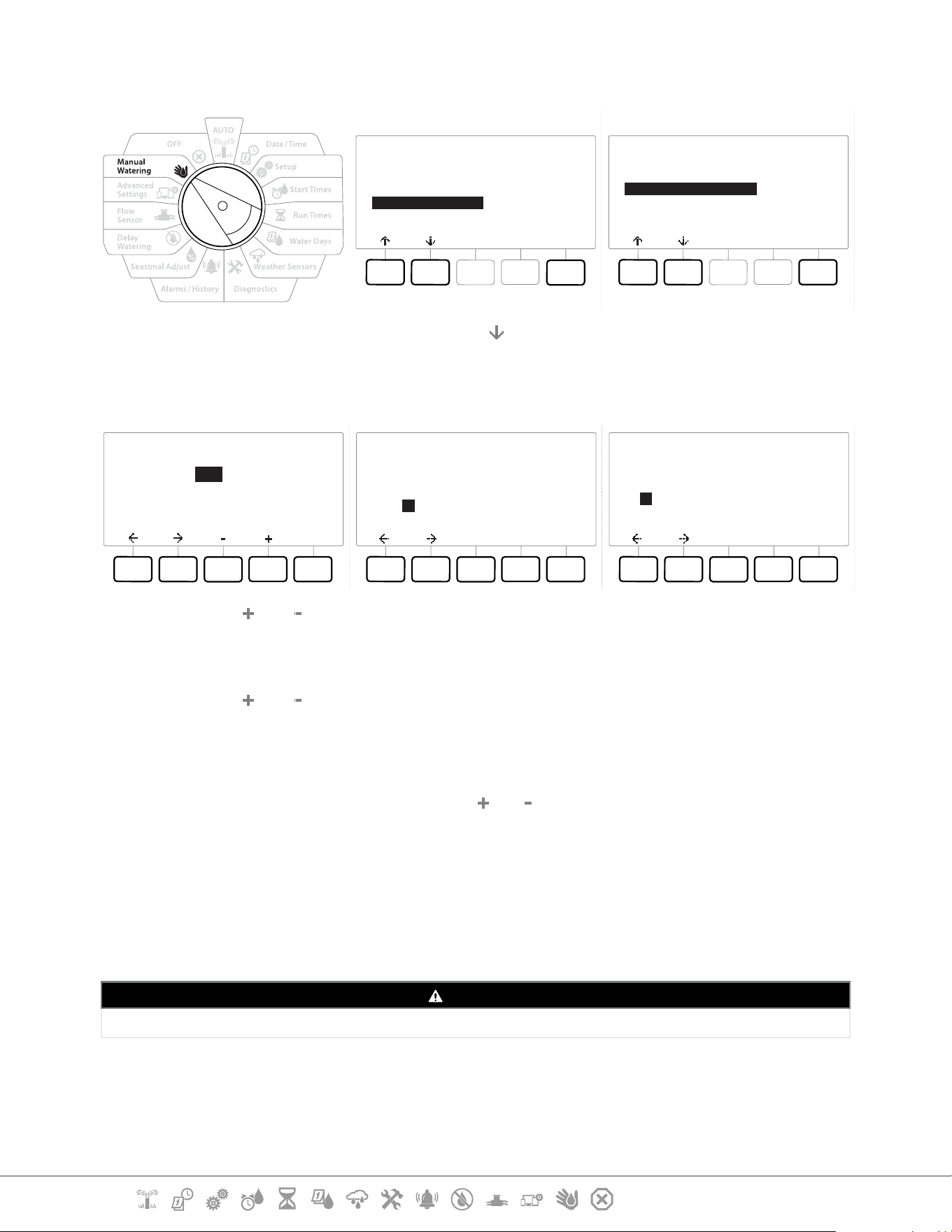
Current Section: Manual Watering 79
Navigation:
Set Up MV Water Window
Manual Watering
Next
Start Station
Start Program
MV Water Window
Test All Stations
MV Water Window
Next
Set MV Water Window
Manual MV Open
1 At the Manual Watering screen, press the key to select “MV Water Window”, then press
Next .
2 At the MV Water Window screen, with “Set MV Water Window” selected, press Next .
MV Water Window
Next
OFF
OFF
N/A
HH:MM
Start:
End:
Duration:
MV Water Window Days
Manual Watering
NextNoYes
Mo
Y
Tu
N
We
N
Th
N
Fr
N
Sa
N
Su
N
Water Window MVs
MVs Included in
Water Window:
MV
--
DoneNoYes
1
Y
2
N
4 Press the and keys to set the MV Water Window Start time.
5 Press the Arrow keys to navigate between the number setting elds.
6 Press the
and keys to set the time when the End time. The duration of your MV
Water Window calculates automatically, then press Next .
•
Press and HOLD keys to accelerate settings.
•
To clear a previously set MV Water Window, press the and keys to set both the Open and Close times to
OFF (between 11:59 PM and 12:00 AM).
7 At the MV Water Window Days screen, press the Yes key to allow MV Manual Watering to
occur on a given day or press No to exclude that day. Press Next to advance past Sunday.
8 At the Water Window MVs screen, press the Yes key to include the selected Master Valve
in the Water Window, or press No to exclude that MV.
WARNING
If Water Windows are selected for Pump starts the pump will dead head.
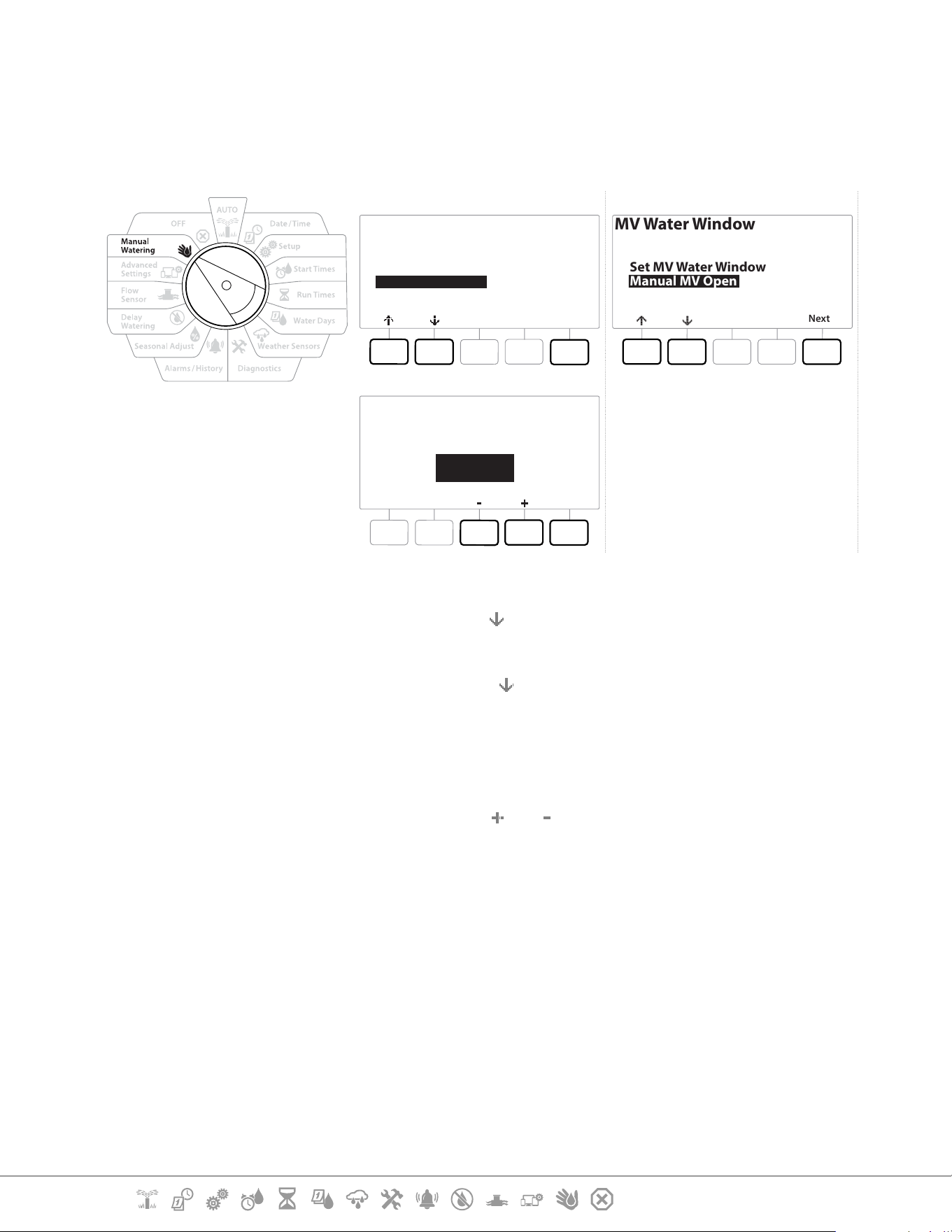
Current Section: Manual Watering 80
Navigation:
15.1.5 Manual MV Open
Occasionally it may be necessary to provide water to the system for unscheduled tasks. The Open
MV feature allows you to leverage settings, such as the maximum additional ow rate, from your MV
Water Window to open MVs for a short time.
Manual Watering
Next
Start Station
Start Program
MV Water Window
Test All Stations
MV Water Window
Next
Set MV Water Window
Manual MV Open
Start
Manual MV Open
MV Open Duration
00:30
HH:MM
1 Turn the controller dial to Manual Watering
2 At the Manual Watering screen, press the key to select “MV Water Window”, then press
Next .
3 At the MV Water Window screen, press the key to select “Manual MV Open”, then press
Next .
4 The Manual MV Open screen appears, showing all MVs that were previously selected to
be included in the MV Water Window. Press Next .
5 At the Manual MV Open screen, press the and keys to set the duration (in hours and
minutes) for the MV to be open, then press Start.
•
Press and HOLD keys to accelerate settings.
6 The Conrmation screen appears.

Current Section: OFF 81
Navigation:
16. OFF
Use this Dial position to turn o irrigation, master valve or pump and adjust display contrast.
16.1.1 Adjust Display Contrast
For better visibility, you can adjust contrast values of the controller display from 1-12 in the OFF
position.
1 Turn the controller dial to OFF
2 At the All Watering O screen, press the and keys to adjust contrast up or down
(from 0 to 12).
16.1.2 Close Master Valves
Closes all master valves, disabling irrigation.
NOTICE
Using the MV Close function will disable all irrigation functions.
•
The Close Master Valves function closes Normally Open Master Valves. Normally Closed Master Valves
remain closed.
1 Turn the controller dial to OFF
2 At the All Watering O screen, press the MV Close key.
3 At the conrmation screen, press and HOLD the Yes key for 4 seconds to Close Master
Valves. If you’re not sure, press No.
4 A conrmation screen shows the MV has closed.
5 The OFF dial position screen will now show the message “All MVs Closed. To cancel and
restore irrigation functions, turn the dial to AUTO”.
Current Section: Installation 82
Navigation:
17. INSTALLATION
17.1 Install the Controller
This section explains how to mount the LXME2 controller on a wall (or mounting surface) and
connect the wiring.
•
An optional metal cabinet (LXMM) and pedestal (LXMMPED) or stainless steel cabinet (LXMM-SS) and
pedestal (LXMMPED-SS) are also available for the LXME2 controller. If you intend to purchase those options
then follow the installation instructions included with those items and proceed to the Install Modules section
below.
WARNING
This controller must be installed in compliance with local electrical codes.
17.1.1 Installation Checklist
When installing the LXME2 controller for the rst time, it is recommended that you complete the
following steps in order.
For your convenience a check-o box is provided for each step.
Check box contents
Select a location
Gather installation tools
Mount the controller
Connect source power
Install base and station module[s]
Connect eld wiring
Complete the installation
17.1.2 Check Box Contents
All components below are included with your LXME2 controller and are required for installation. If
anything is missing, please contact your distributor before proceeding.
• LXME2 controller
• Controller cabinet keys
• Mounting hardware (5 screws, 5 plastic wall anchors)
• Quick Start Guide/ Programming Guide
• Controller mounting template
• Station Numbering Labels

Current Section: Installation 83
Navigation:
17.2 Select Location for Controller
Select a location that:
• Easily accessible and allows for comfortable viewing
• Has a at wall surface
• Near 120 VAC or 230/240 VAC power source (depending on model)
• Is safe from potential vandalism
• Is outside the range of operating sprinklers
17.2.1 Gather Installation Tools
Before beginning installation, gather the following tools and materials:
• Slotted Head Screwdriver
• Philips Head Screwdriver
• Thin Blade Screwdriver
• Lineman’s Pliers
• Torpedo Level
• Hammer
• Grounding Strap
• #8 AWG or #10 AWG Bare Ground Wire
• WC20 Waterproof Wire Connectors
• Tape Measure
• Wire Stripper
• Wire Nuts (provided)
• Marking Pencil
• Electric drill (or Hammer Drill if installing in masonry or concrete wall)
• Waterproof Caulking

Current Section: Installation 84
Navigation:
17.2.2 Access Controller Cabinet
1 The controller comes with an outer door lock to deter vandalism and prevent
unauthorized access to controller operations. If necessary, unlock the cabinet door using
the supplied key.
2 Grasp the handle on the right-hand-side of the outer cabinet and pull it towards you to
open the door, swinging it to the left.
3 Open or Remove Controller Front Panel. Grasp the handle on the right-hand-side of the
controller front panel and pull it towards you to open the cabinet, swinging it to the left.
4 To remove the front panel: disconnect the ribbon cable from the front panel by gently
pulling the connector out of the socket.
NOTICE
Be careful not to bend the pins in the sockets when attaching or detaching the ribbon cable.
5 Rock the front panel upward and nudge the bottom corner pin out of the lower pin-
hole to remove the front panel.

Current Section: Installation 85
Navigation:
17.3 Mount the controller
•
Before mounting the controller, we recommend that you remove the controller front panel, plus the LXME2
Base Module and/or any station modules if previously installed.
1 Using a level, tape the mounting template to the mounting surface at approximately
eye level. Make sure that at least one of the ve mounting hole marks is aligned on a
wall stud or other solid surface.
2 Use a tapping tool (or nail) and hammer to tap pilot holes through the ve mounting
hole marks and into the mounting surface.
3 Then remove the template and drill holes in the mounting surface, installing wall
anchors if necessary.
4 Drive the rst screw into the top most-center hole. Then hang the controller on the
screw by the key-hole slot on the back of the cabinet.
5 Line up the controller cabinet mounting holes with the remaining pilot holes and drive
the four remaining screws through the cabinet back plane into the mounting surface.
6 Connect Power to the Controller
7 Surge Protection and Grounding
8 The LXME2 controller is equipped with built-in electrical surge protection. For this
system to function, you must properly ground the controller.
WARNING
The LXME2 controller must be properly surge protected and grounded. Doing so can help prevent damage to the
controller and irrigation system and also signicantly reduce troubleshooting, repair time and expense. Failure to do so
could result in failure of your controller and voiding the warranty.
Ensure that all grounding devices are compliant with local electrical codes.
17.4 Connect source power
The ESP-LXME2 controller has an internal transformer that reduces supply voltage (120 VAC in U.S.
models; 230 VAC in international models; 240 VAC in Australian models) to 24 VAC. You will need to
connect power supply wires to the transformer’s three wires. (Line, Neutral, Ground)

Current Section: Installation 86
Navigation:
WARNING
Electric shock can cause severe injury or death. Make sure power supply is turned OFF before connecting power wires.
All electrical connections and wiring runs must be made according to local building codes.
1 Locate the transformer wiring compartment in the lower left corner of the controller
cabinet. Remove the screw on the right-hand side and pull the cover o to expose the
wiring compartment.
17.4.1 Install base and station module (BCM or PSM)
1 Install Base Module (BM2-LXME) or ProSmart module (PSM-LXME2) in Slot 0.
CAUTION:
Be careful not to bend the pins in the sockets when installing the module.
•
The Base and Flow Smart Module include a jumper wire connecting the weather sensor (SEN) terminals. Do
not remove the jumper wire unless you install a weather sensor.
2 Orient the connector on the bottom of the module with the connection socket in Slot 0
on the controller backplane.
3 Carefully fasten the module onto the controller backplane, pressing rmly until it
snaps into place. The red light on the module will ash on and o once if the module is
installed correctly. If the light does not ash once, verify the module is seated correctly.
•
To remove the module, press in on the (two) release buttons on either side of the module.
17.4.2 Install Station Module
Install a 12 station module in Slot 1 that was included with your LXME2 controller. Additional station
modules can be purchased separately.
•
The LXME2 is only compatible with 12 station modules (ESPLXM-SM12) and will not work with 8 or 4 station
modules.
CAUTION:
Be careful not to bend the pins in the sockets when installing the module.
1 Orient the connector on the bottom of the station module with the connection socket
in Slot 1 on the controller backplane.
2 Carefully fasten the module onto the controller backplane, pressing rmly until it
snaps into place. The red light on the module will ash on and o once if the module is
installed correctly. If the light does not ash once, verify the module is seated correctly.
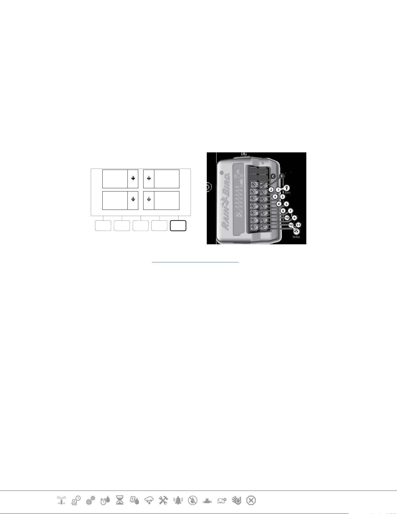
Current Section: Installation 87
Navigation:
•
To remove a module, press in on the (two) release buttons on either side of a module.
17.5 Dynamic Station Numbering
A Module Conguration screen is displayed whenever the LXME2 Controller detects a change in
module conguration. The Module Summary screen displays the module type detected in each
module slot along with the station numbers. With the Module Labels screen displayed. Locate the
Module Station Numbering Labels that are provided on a separate foldout sheet.
The Module Station Numbering Screen displays a pair of letters (example: Slot 1 = Label AC) for each
installed module. Find the station numbering label on the foldout sheet with the matching letter pair
and place it over the blue strip on the module. This label shows which station number each terminal
block is mapped to.
Done
SM12 SM12
SM12SM12
01
1
2
3
4
12
25
36
37
48
13
24
AC
AL
BG
BP
•
For alternate station numbering see Module/ Station Numbering
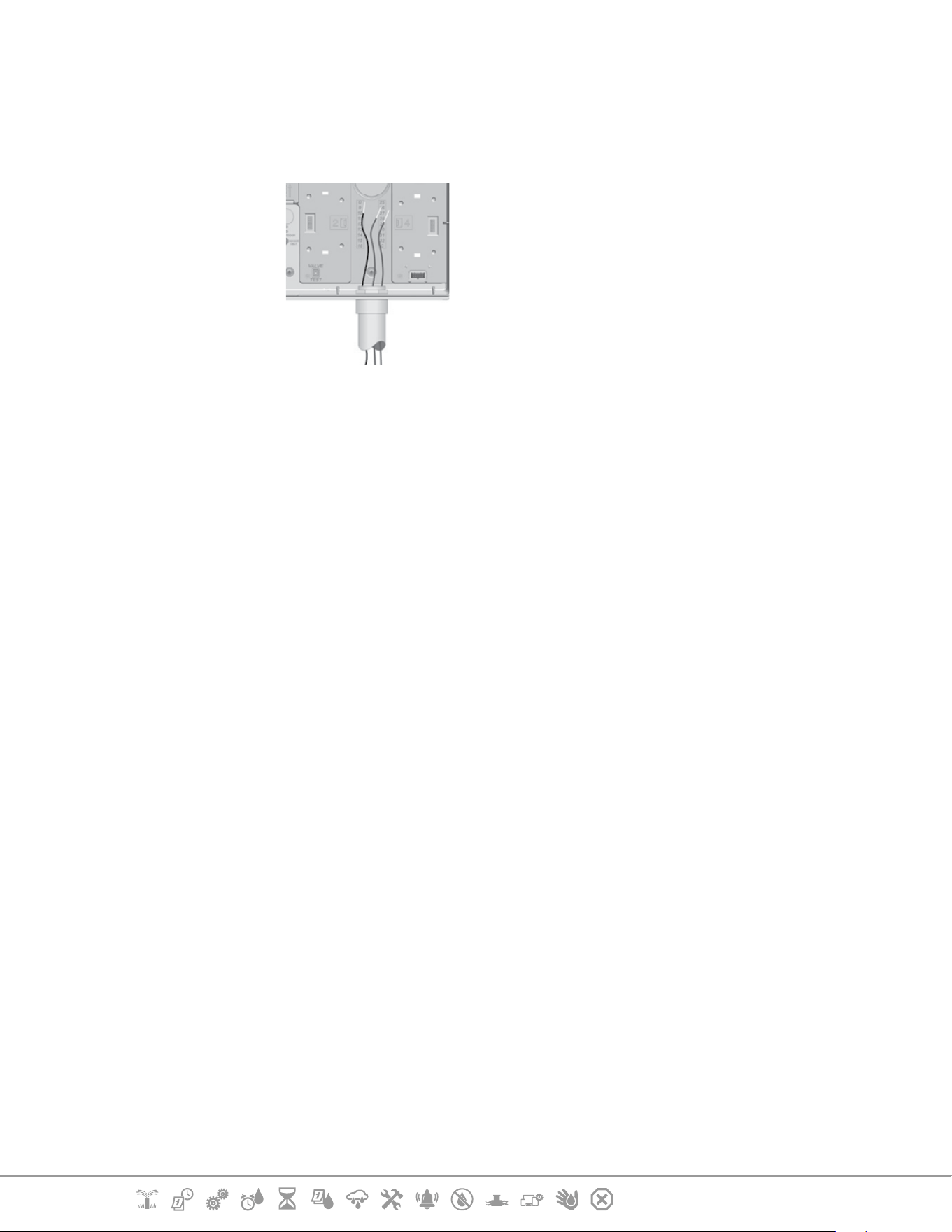
Current Section: Installation 88
Navigation:
17.5.1 Connect Field Wiring
1 Locate (or remove) the large knockout on the bottom of the controller cabinet.
2 Attach a conduit tting to the bottom of the cabinet; then attach conduit to the tting.
3 Feed the eld wires through the conduit and into the controller cabinet.
4 Strip the wire jacket back by a maximum of 1/2 inch (12 mm) and connect each valve
wire to one of the numbered terminals on a station module.
5 Field wires for valves are connected to module terminals using screw terminal blocks,
loosen the screws of the appropriate terminal using a Philips screw driver.
6 Insert the wire. Then tighten the screw to clamp the wire in place.
7 Connect the common wire(s) to any one of the COM terminals on the controller. Wires
used to connect the valves must be code approved for underground installation.
•
Complete the following step only if your system uses a master valve or a pump start relay. The controller
does not provide main power for a pump.
8 Connect the master valve or pump start relay wiring to the MV and COM terminals.
9 Once wiring is completed, ll top of conduit with waterproof caulking to prevent insect
intrusion into the controller cabinet.
17.5.2 Connect Local Weather Sensor
The LXME2 can accept input from a single weather sensor wired directly to the controller or through
a wireless receiver.

Current Section: Installation 89
Navigation:
A local weather sensor can be bypassed from the Weather sensor setup screen.
To Enable a Local Weather Sensor see Weather Sensors.
•
Follow the sensor manufacturer’s instructions to correctly install and make wire connections to the sensor.
Ensure the sensor installation is in compliance with all local codes.
•
If your weather sensor requires 24V power from the controller, the + and - connectors to the left of the sensor
and common connectors can be used.
1 Run continuous sensor wire from the weather sensor to the LXME2 controller.
2 Route wire through knockout on the bottom of the controller.
3 Remove the yellow jumper wire (if present). Connect the two sensor wires to
the sensor (Sen) inputs. When nished, tug gently on the wires to make sure the
connections are tight.
•
Ensure that the conguration for your controller and irrigation programs are set up correctly for your
sensor. For example, if one of your programs is set up to manage your landscape lighting you may
want to ensure that it’s stations ignore input from a local weather sensor. See Weather Sensor, for
more details.
4 Complete the installation
5 Install Front Door
6 Line up the three door hinges with the plastic posts on the controller.
7 Press the hinges onto the posts until the front door snaps into place.
17.5.3 Connect a Flow Sensor - Models Only
A Pro Smart Module (PSM-LXME2) is required to connect a Flow Sensor and use FloWatch, Learned
Flow utility and Flow Alarm/ water use recording.
•
You may have to replace the BM2-LXME Base Module with the PSM-LXME2 Flow Smart Module, depending
on the conguration you purchased.
•
The Pro Smart Module includes a jumper wire connecting the weather sensor (SEN) terminals. Do not

Current Section: Installation 90
Navigation:
remove the jumper wire unless you install a weather sensor.
1 Install the ow sensor in the eld according to the manufacturer’s instructions, and run
the ow sensor wire to the ESP-LXME2 controller.
2 Use a separate PE-39 #19 AWG cable for connecting the ow sensor to the Pro Smart
Module. The maximum wire run length is The maximum wire run length is 2000 feet
(610 meters).
3 The connection from the PE-39 cable to the ow sensor must be made with direct burial
type connectors. Use Rain Bird WC20 or 3M DBR/Y-6 splice kits only.
4 Minimize wire splices.
5 Any cable with broken, torn, or damaged insulation should be replaced.
6 Route the ow sensor wire through the knockout on the bottom of the controller.
7 Connect the ow sensor wire to the Flow + and Flow - inputs. When nished, tug gently
on the wires to make sure the connections are tight.
•
For Rain Bird FS-Series ow sensors, connect the red sensor wire to the red (+) terminal and the black sensor
wire to the grey (-) terminal.
17.5.4 Verify Field Installation
1 Once some or all valves have been wired and programmed into the LXME2
controller you can check the electrical portion of the installation even if water is
not available to test the valves.
2 If water is available and you would like to test some or all of your stations, the
easiest way to do so is by using the Test All Stations feature of the controller. See
Test all Stations for more details.

Current Section: Installation 91
Navigation:
Rain Bird Corporation
6991 East Southpoint Road Tucson, AZ 85756
USA
Tel: (520) 741-6100
Rain Bird Europe SNC
Rain Bird France SNC
240 rue René Descartes Bâtiment A, Parc Le Clamar
BP 40072
13792 AIX-EN-PROVENCE CEDEX 3 FRANCE
Tel: (33) 4 42 24 44 61
www.rainbird.eu
www.rainbird.fr
Rain Bird Corporation
970 W. Sierra Madre Ave. Azusa, CA 91702 USA
Tel: (626) 812-3400
Rain Bird Deutschland GmbH
Königstraße 10c 70173 Stuttgart DEUTSCHLAND
Tel: +49 (0) 711 222 54 158
Rain Bird Australia Pty Ltd.
Unit 13, Level1
85 Mt Derrimut Road PO Box 183 Deer Park, VIC
3023
Tel: 1800 724 624
[email protected]d.com.au
www.rainbird.com/au
Rain Bird International
1000 W. Sierra Madre Ave. Azusa, CA 91702 USA
Tel: +1 (626) 963-9311
Rain Bird Ibérica S.A.
C/ Valentín Beato, 22 2a Izq. fdo 28037 Madrid
ESPAÑA
Tel: (34) 91 632 48 10
www.rainbird.es
portugal@rainbird.eu
www.rainbird.pt
Rain Bird Brasil Ltda.
Rua Marques Póvoa, 215 Bairro Osvaldo Rezende
Uberlândia, MG, Brasil CEP 38.400-438
Tel: 55 (34) 3221-8210
www.rainbird.com.br
Technical Services for U.S. and Canada only:
1 (800) RAINBIRD
1-800-247-3782
www.rainbird.com
Rain Bird Turkey
Çamlık Mh. Dinç Sokak Sk. No.4 D:59-60 34760 Ümraniye,
İstanbul TÜRKIYE
Tel: (90) 216 443 75 23
www.rainbird.com.t
© 2022 Rain Bird Corporation
”Rain Bird” and “Flo-Manager” are registered trademarks of Rain Bird Corporation.
D42069 Rev.01/22