LNK
TM
Ready
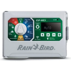
ESP-ME3 Controller
Advanced User Manual
ESP-ME3 Controller
2
EN
ESP-ME3 Controller · Advanced User Manual
Technical Support
Questions?
Call Rain Bird toll free Technical Support at
1-800-724-6247 (USA and Canada only)
Hazardous Warnings
CWARNING
Indicates a hazardous situation that, if not avoided,
could result in death or serious injury.
CCAUTION
Indicates a hazardous situation that, if not avoided,
could result in minor or moderate injury.
NOTICE
Indicates information considered important, but not
hazard-related (e.g., messages relating to property
damage).
SAFETY INSTRUCTIONS
Specific safety-related instructions or procedures
are described.
Symbols & User Operation
a
NUMBERS define a series of steps for the user to
follow in order to operate the controller.
B
NOTE: Notifies the user of important operating
instructions related to controller functionality,
installation or maintenance.
H
REPEAT: Indicates that a repetition of previous
steps or actions may be required for further oper-
ation, or to complete a process.
Contents
Technical Support ......................................................... 2
Introduction ..................................................3
Welcome to Rain Bird® ................................................. 3
The Intelligent Use of Water® .........................................3
ESP-ME3 Controller Features ...................................... 3
WiFi Enabled .........................................................................3
Installation ...................................................4
Mount Controller .......................................................... 4
Connect Valves ....................................................................4
Connect Master Valve (optional) ...................................4
Connect Pump Start Relay (optional) .......................... 5
Connect Flow Sensor (optional) ....................................5
Connect Weather Sensor (optional) ............................. 6
Connect Power ....................................................................6
Station Expansion Modules ........................................ 7
Install Modules ....................................................................7
Station Numbering ............................................................8
Complete Controller Installation ............................... 8
Normal Operation ........................................8
Controls and Features .................................................. 8
AUTO .......................................................................................9
OFF ...........................................................................................9
Display Indicators ......................................................... 9
Basic Programming ....................................10
1. Set Date and Time .................................................. 10
2. Set Watering Start Times ...................................... 10
3. Set Station Run Times ...........................................10
4. Set Water Days ........................................................ 10
Custom Days of the Week .............................................10
Program-Based Scheduling ...................................... 11
Common Programming Error .....................................11
Manual Watering Options ..........................11
Test All Stations ...........................................................11
Run a Single Station ...................................................11
Run a Single Program ................................................ 12
Advanced Programming ............................12
Odd or Even Calendar Days ......................................12
Cyclic Days ....................................................................12
Seasonal Adjust ...........................................................13
Delay Watering ............................................................ 13
Permanent Days Off ...................................................13
Special Features..........................................14
Options ....................................................... 14
Reset Button ................................................................14
Remote Accessories ....................................................14
Detached Programming ............................................ 15
Battery Life ...................................................................15
Appendix .....................................................15
Troubleshooting .........................................................15
Error Detection ................................................................. 15
Programming Errors (blinking LED) .......................... 15
Electrical Errors (non-blinking LED) ..........................15
Flow Alarms .......................................................................16
Watering Issues................................................................. 16
Electrical Issues (solid LED illuminated)................... 17
Certifications ...............................................................18
Safety Information .....................................................18
ESP-ME3 Controller
3
EN
Introduction
Welcome to Rain Bird®
Thank you for choosing Rain Bird’s ESP-ME3 controller.
In this manual are step by step instructions for how to
install and operate the ESP-ME3.
The Intelligent Use of Water®
We believe it is our responsibility at Rain Bird to
develop products that use water efficiently.
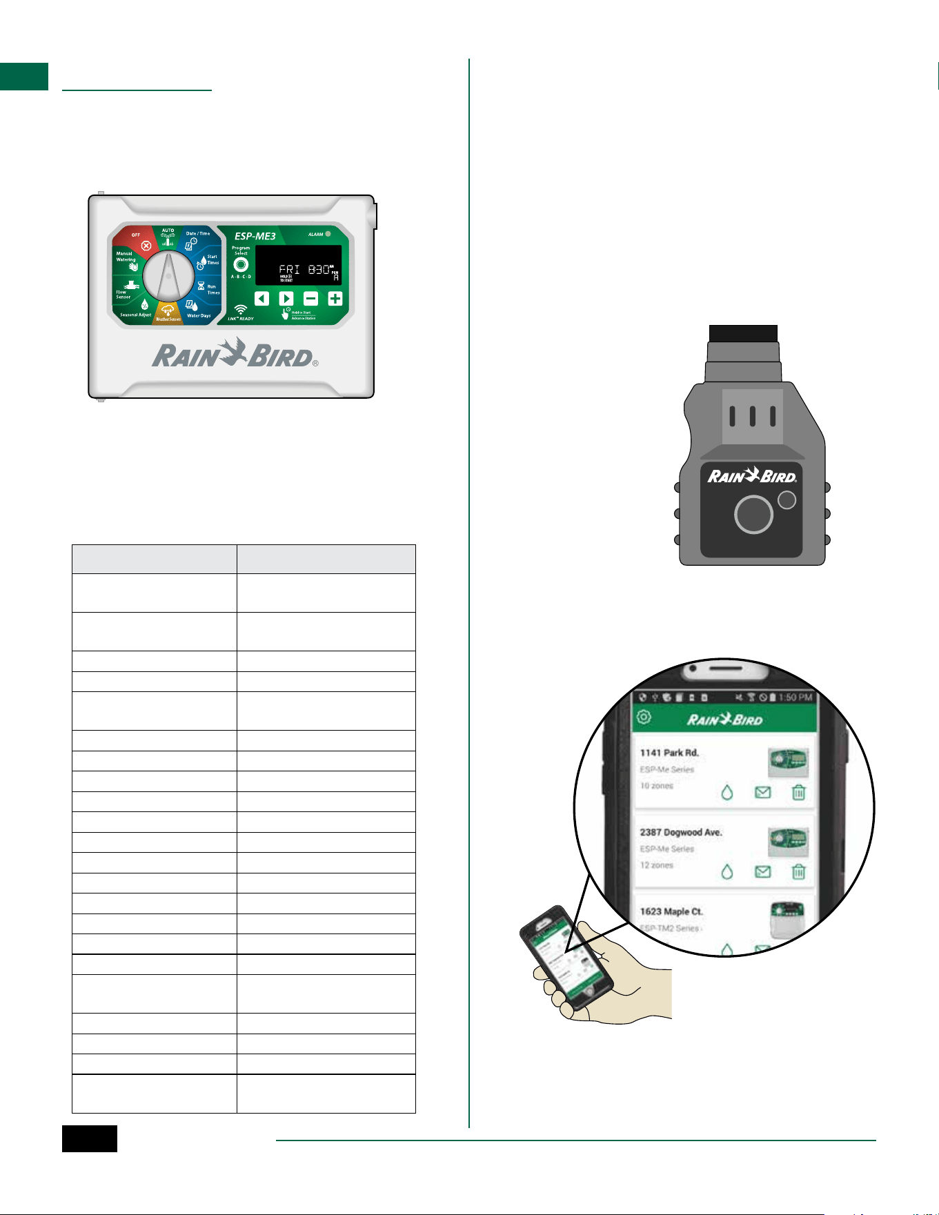
ESP-ME3 Controller Features
Feature Description
Maximum Stations 22 (with optional Station
Modules)
Master Valve or Pump
Start Relay
Supported
Start Times 6
Programs 4
Program Cycles Custom Days, Odd, Even and
Cyclic
Permanent Days Off By program
Master Valve Control On/Off per station
Rain Delay Supported
Rain/Freeze Sensor Supported
Rain Sensor Control Global or by station
Seasonal Adjust Global or by program
Manual Watering Run Yes
Manual Program Run Yes
Manual Test All Stations Yes
Short Detect Yes
Delay Between Stations Set by program
Accessory Port Yes (5 pin)
Save & Restore Program-
ming
Yes
Station Advance Yes
LNK
TM
WiFi Module Supported
Flow Sensor Supported
Cycle+Soak
TM
Supported in Rain Bird App
via LNK
TM
WiFi Module
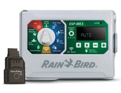
WiFi Enabled
The LNK
TM
WiFi Module allows remote connection to
a Rain Bird ESP-ME3 Controller using an Apple® iOS® or
Android
TM
compatible smart device. The mobile appli-
cation allows remote access and configuration of one
or more irrigation controllers.
* Apple is a trademark of Apple Inc, IOS is a trademark
of Cisco Systems Inc, and Android is a trademark of
Google LLC.
For more information on the LNK
TM
WiFi Module and
the value this product can provide for your ESP-ME3
controller, please visit: http://wifi-pro.rainbird.com
LNK
TM
WiFi Module
(sold separately)
Manage Sites Remotely
ESP-ME3 Controller
4
EN
Installation
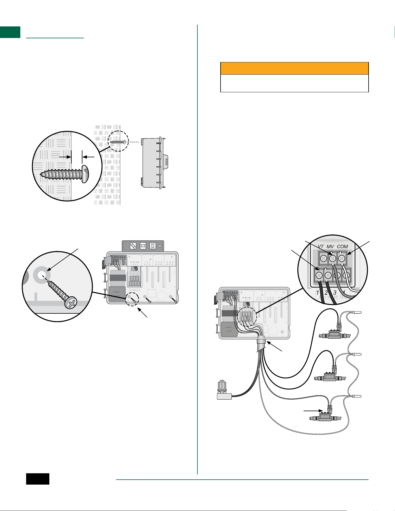
Mount Controller
B
NOTE: Choose a suitable mounting location close
to a 120VAC wall outlet.
a
Drive a mounting screw into the wall, leaving an
1/8 inch gap between the screw head and the
wall surface (use the supplied wall anchors if
necessary), as shown.
b
Locate the keyhole slot on back of the controller
unit and hang it securely on the mounting screw.
1/8 IN.
a
b
c
Open the front panel, and drive three additional
screws through the open holes inside the
controller and into the wall, as shown.
c
a
b
MASTER
VALVE
COMCOM
MVMV
11
22
SENSSENS
e c
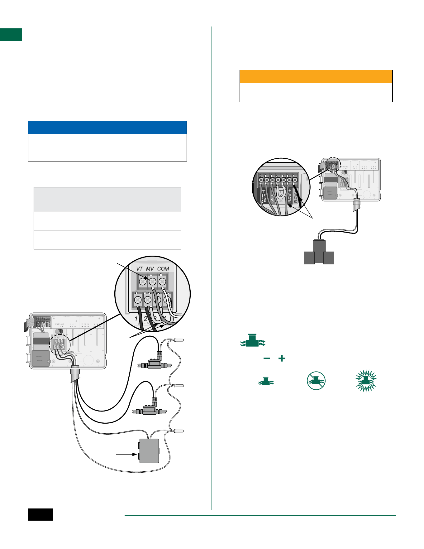
Connect Valves
a
Route all field wires through the opening at the
bottom or back of the unit. Attach conduit if
desired, as shown.
CWARNING
Do not route valve wires through the same opening
as power wires.
b
Connect one wire from each valve to the terminal
on the Base Module or Station Module that
corresponds to the desired station number (1-22).
c
Connect a field common wire to the COM
(common)terminal on the Base Module. Then
connect the remaining wire from each valve to
the field common wire, as shown.
d
To perform a Valve Test, connect the common wire
to the COM terminal and the power wire to the VT
terminal. This will immediately turn the valve ON.
Connect Master Valve (optional)
e
Connect a wire from the master valve to the MV
(master valve) terminal on the Base Module.
Then connect the remaining wire from the master
valve to the field common wire, as shown.
ESP-ME3 Controller
5
EN
Connect Pump Start Relay (optional)
a
Connect a wire from the PSR (pump start relay)
to the MV (master valve) terminal on the Base
Module. Then connect another wire from the
pump start relay to the field common wire, as
shown.
b
To avoid the possibility of damage to the pump,
connect a short jumper wire from any unused
terminal(s) to the nearest terminal in use, as
shown.
NOTICE
The ESP-ME3 controller DOES NOT provide power for
a pump. The relay must be wired according to manu-
facturer instructions.
Only the following Rain Bird pump start relay models
are compatible with the ESP-ME3:
Description Note Model
No.
Universal Pump Relay 110 volt
only
PSR110IC
Universal Pump Relay 220 volt
only
PSR220IC
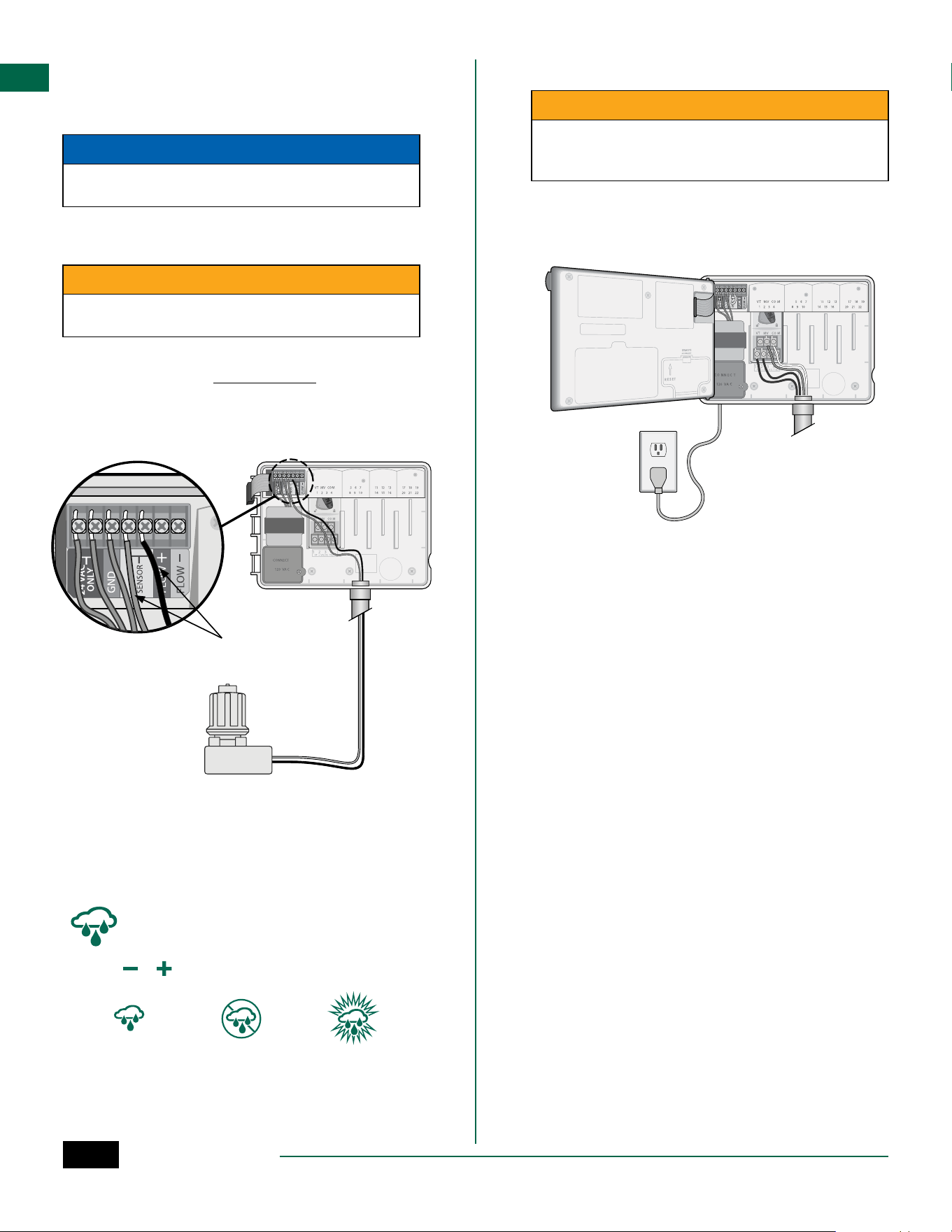
Connect Flow Sensor (optional)
B
NOTE: Install the flow sensor in the field accord-
ing to the manufacturer’s instructions.
a
Run the flow sensor wires to the controller.
CWARNING
Do not route valve wires through the same open-
ing as power wires.
b
Connect both flow sensor wires to the Flow
terminals, as shown. Be sure to connect the
positive (sometimes red) sensor wire to the
red (+) terminal and the negative (sometimes
black) sensor wire to the grey (-) terminal.
b
Flow Sensor Settings
Set the controller to obey or ignore a flow sensor.
When set to Sensor ON, automatic irrigation will
be suspended per station if detected flow exceeds
learned flow by more than 30%. When set to Sensor
OFF, all stations will ignore the flow sensor.
Turn the dial to Flow Sensor.
• Press
or to select SENS ON (sensor on) or SENS
OFF (sensor off).
Sensor ON Sensor OFF Flow detected
(flashing)
B
NOTE: When switching from Sensor OFF to Sen-
sor ON, the controller will begin to LEARN FLOW.
It will run each station for short period to set the
expected station flow.
B
NOTE: See Troubleshooting section of the Appen-
dix for Flow Alarms information.
a
B
NOTE: Connection to
pump and external
power not shown.
Refer to pump instal-
lation instructions.
PUMP START
RELAY
b
COMCOM
PSRPSR
11
22
ESP-ME3 Controller
6
EN
Connect Weather Sensor (optional)
a
Remove the yellow jumper wire from the SENSOR
terminals on the controller.
NOTICE
Do not remove the yellow jumper wire unless con-
necting a rain sensor.
b
Connect both rain sensor wires to the SENSOR
terminals as shown.
CWARNING
Do not route the rain sensor wires through the same
opening as the power wiring
B
NOTE: Rain Bird ESP-ME3 controllers are only
compatible with normally closed rain sensors.
B
NOTE: For wireless rain/freeze sensors, refer to
the sensor installation instructions.
b
Connect Power
CWARNING
DO NOT plug in the transformer or connect external
power until you have completed and checked all
wiring connections.
Installation with Pre-attached Cord
• Plug the attached power cord into a nearby 120VAC
electrical outlet.
Weather Sensor Settings
Set the controller to obey or ignore a weather sensor.
When set to Sensor ON, automatic irrigation will be
suspended if rainfall is detected. When set to Sensor
OFF all stations will ignore the rain sensor.
Turn the dial to Weather Sensors.
• Press
or to select SENS ON (sensor on) or SENS
OFF (sensor off).
Sensor ON Sensor OFF Rain detected
(flashing)
ESP-ME3 Controller
7
EN
Outdoor Installation with Direct Wiring
CWARNING
Electric shock can cause severe injury or death. Make
sure power supply is turned OFF before connecting
power wires.
POWER WIRING CONNECTIONS 120VAC
Black supply wire (hot) to the black transformer wire
White supply wire (neutral) to the white transformer
wire
Green supply wire (ground) to the green transformer
wire
a
Locate the transformer wiring compartment in
the lower left corner of the controller unit. Use a
screwdriver to remove the cover and expose the
transformer connection wires.
b
Route the three external power source wires
through the conduit opening at the bottom of
the unit and into the wiring compartment.
c
Using the provided wire nuts, connect the
external power source wires (two power and one
ground) to the transformer connection wires
inside the wiring compartment.
CWARNING
Ground wire must be connected to provide electrical
surge protection. Permanently mounted conduit
shall be used for connecting main voltage to the
controller
d
Verify that all wiring connections are secure,
then replace the wiring compartment cover and
secure it with the screw.
a
c
b
Station Expansion Modules
Optional Station Modules can be installed in the empty
slots to the right of the Base Module to increase the
station capacity up to 22 stations.
B
NOTE: 6-Station Modules are compatible with
ESP-ME3 and ESP-Me. They are not backwards
compatible with the ESP-M vintage controller.
B
NOTE: For ideal station sequencing, insert 3-Sta-
tion module after inserting all 6-station modules.
For more details see the Station Numbering sec-
tion.
3-STATION
(ESPSM3)
6-STATION
(ESPSM6)
Expansion Modules
(sold separately)
Base Module
(included)
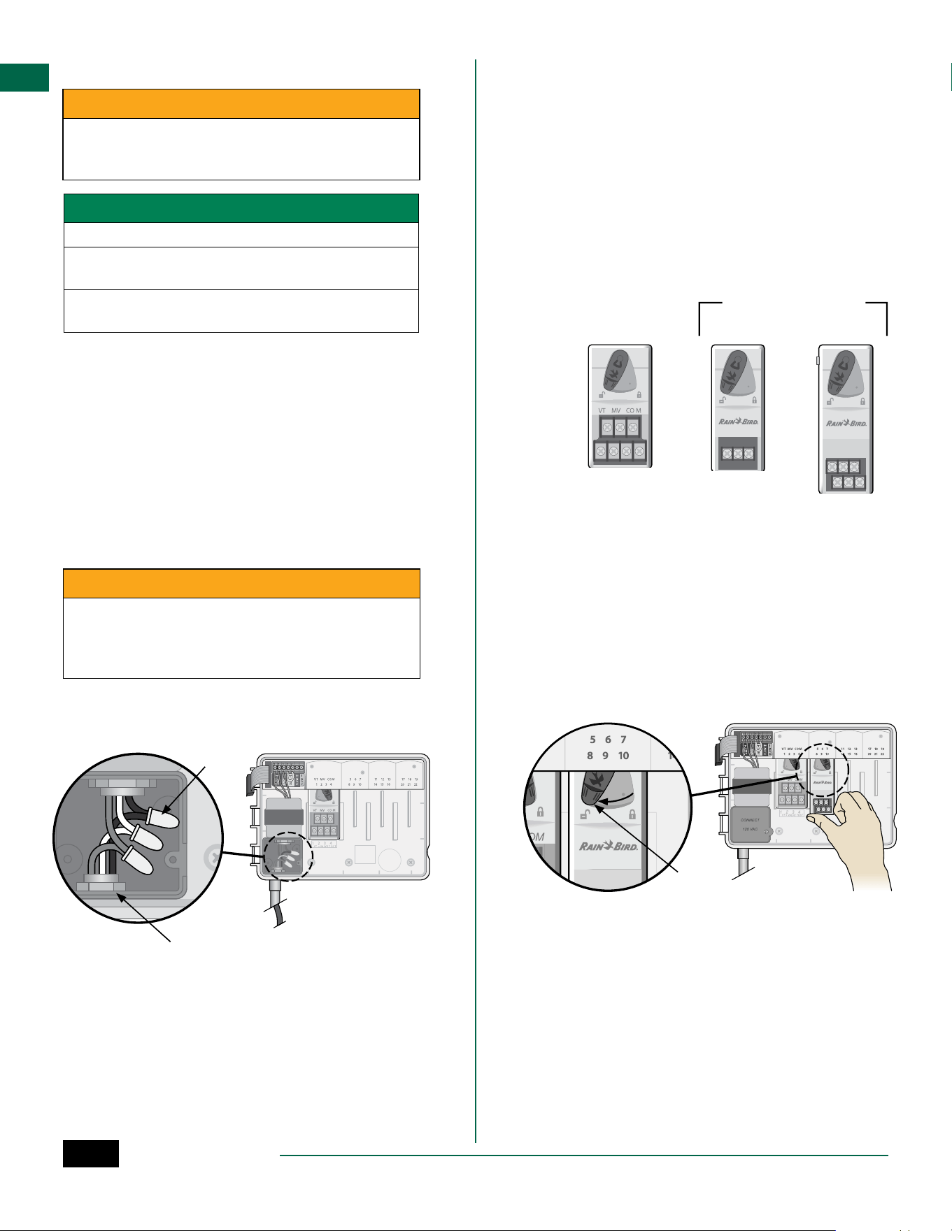
Install Modules
a
Verify the securing lever on the module is in the
unlocked position (slide to the left).
b
Place the module under the desired slot between
the plastic rails.
c
Push the module up into the slot until secure.
d
Slide the securing lever to the locked position
(slide to the right).
b c
d
a
H
REPEAT for additional modules.
B
NOTE: Modules can be installed or removed with
OR without AC power connected. They are con-
sidered “hot-swappable”.
B
NOTE: It take about 30 seconds for stations to
become available for configuration after install-
ing a new module.
ESP-ME3 Controller
8
EN
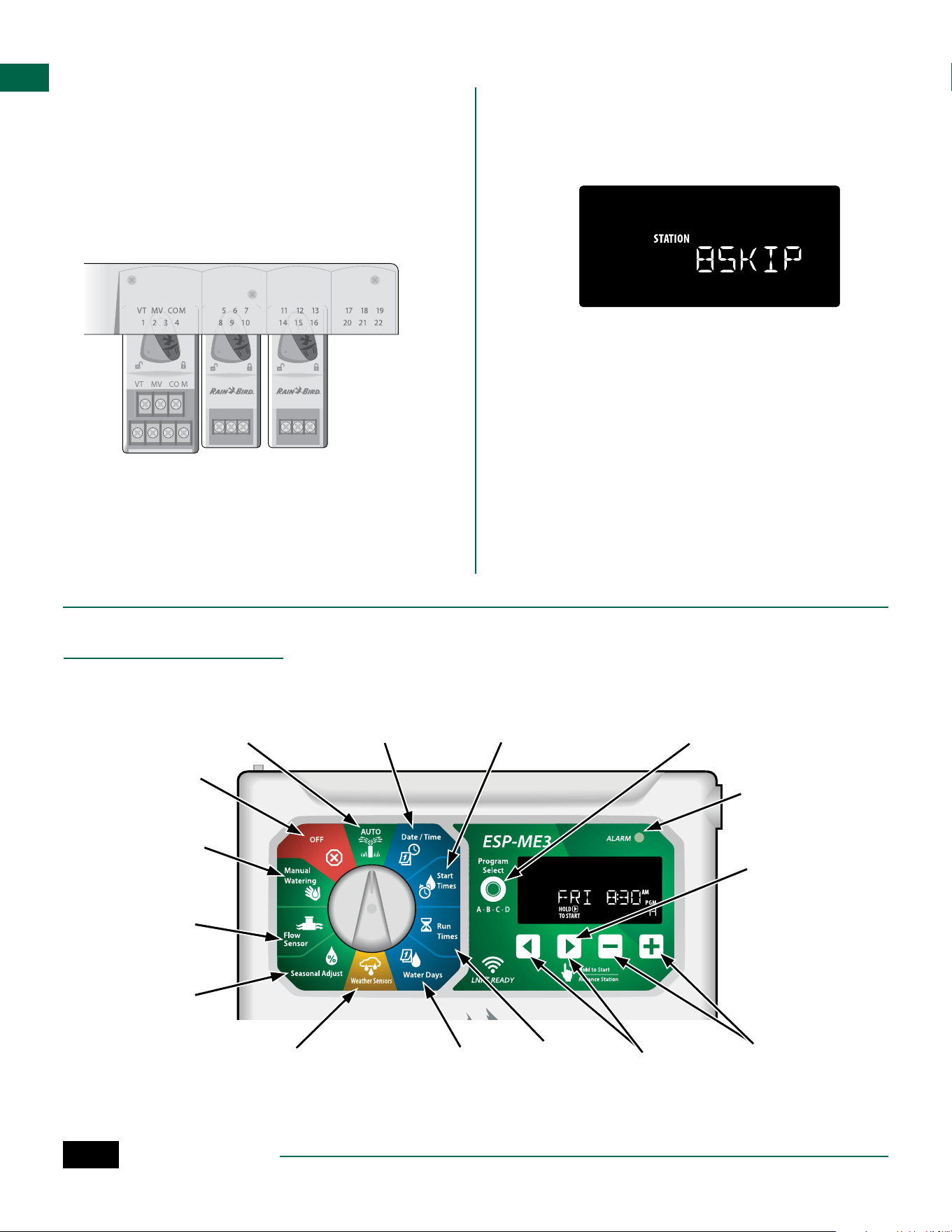
Station Numbering
The controller is configured with “fixed station num-
bering”, meaning that Bays Two, Three and Four can
accept either a 3 or a 6-Station Module. If a 6-Station
Module is NOT installed then the unused stations are
reserved for future use.
Example of Station Numbering when using two
3-Station Modules. A total of 10 stations are installed.
Bay One Bay Two Bay Three Bay Four
• The Base Module is installed in Bay One and uses
Stations 1 through 4.
• A 3-Station Module is installed in Bay Two and
uses stations 5 through 7. Stations 8 through 10 are
skipped and will be unavailable.
• A 3-Station Module is installed in Bay Three and
uses stations 11 through 13.
During programming, the controller will skip any
unused stations, creating a gap in station numbering.
The unused stations will show on the display as 8SKIP,
9SKIP, etc.
If the screen displays 20NOMOD where the 20 is flash-
ing, then there is no module installed for that station
number.
Complete Controller Installation
a
Reinstall and reconnect the front panel.
b
Apply power to the controller and test the system.
B
NOTE: The electrical connections can be checked
even if water is not available. If water is available
and you would like to test some or all of your
stations, use the Test All Stations feature of the
controller.
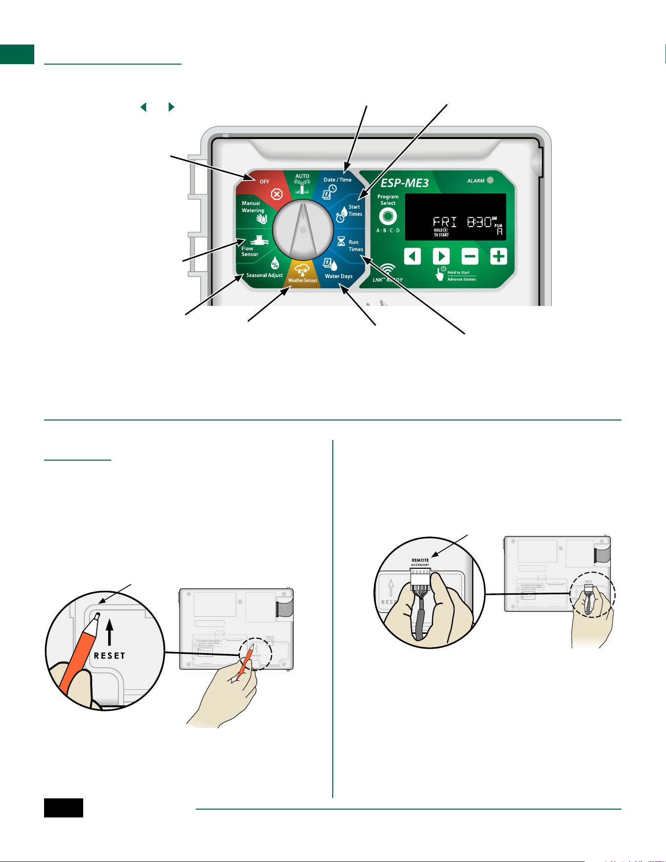
Normal Operation
Controls and Features
Program
Select Button
Select Program
A, B, C or D
Start Times
Up to 6 Start
Times per
program
Run Times
Set station
Run Times
Manual Watering
Start watering for
one or all stations
Weather Sensors
Set controller to
obey or ignore a
weather sensor
Seasonal Adjust
Adjust Run Times
from 5% up to 200%
Back/Next
Buttons
Select
programming
options
– / + Buttons
Adjust feature
settings
OFF
Disables automatic
irrigation
AUTO
Watering occurs
automatically
Date/Time
Set the current
Date and Time
ALARM
Indicator
Hold to Start
Manual
irrigation
Water Days
Select days to
allow watering
Flow Sensor
Set the controller to
obey or ignore
a flow sensor
ESP-ME3 Controller
9
EN
AUTO
AUTO is the normal operating mode. Return the dial to
AUTO when programming is complete.
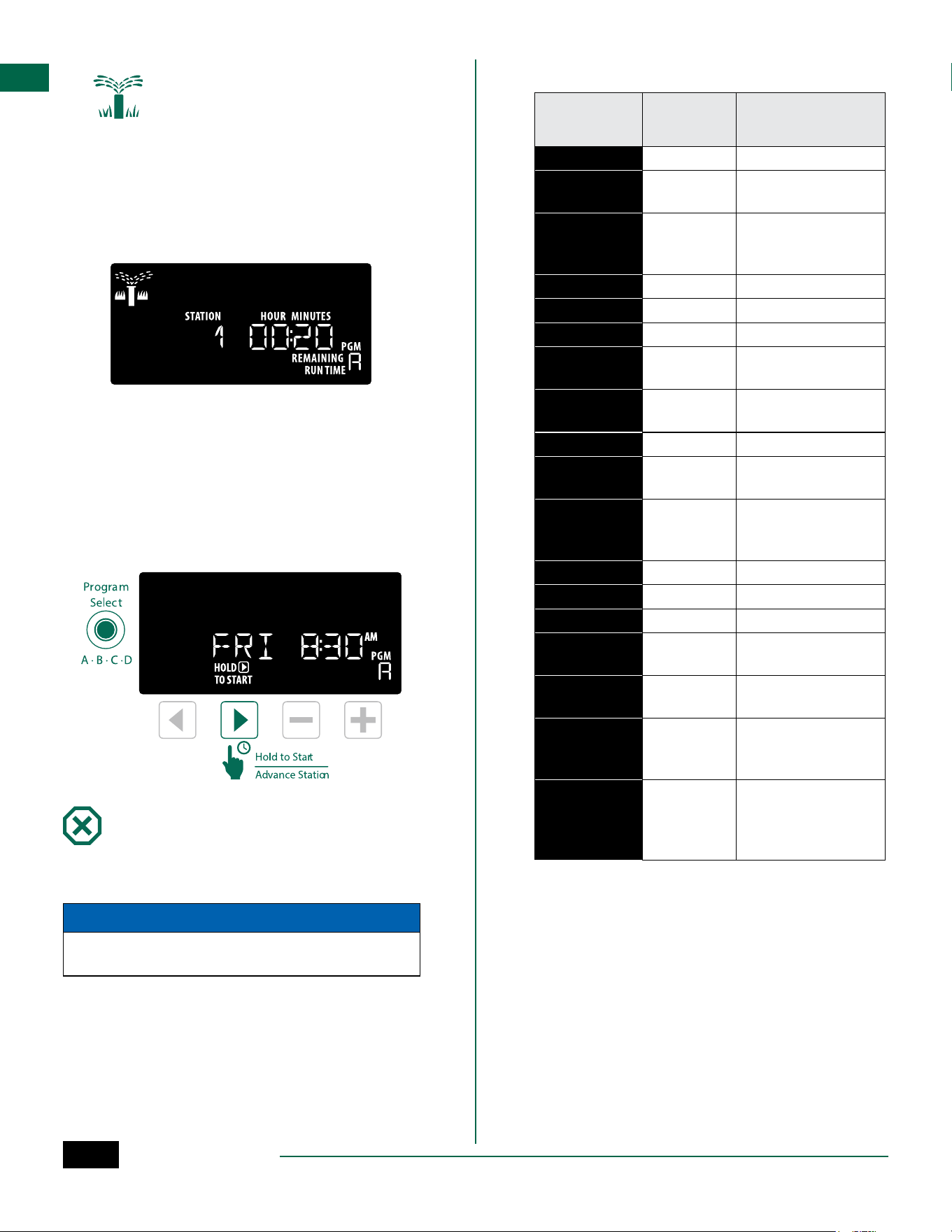
During Watering:
The display shows a blinking sprinkler symbol, the
active Station Number or Program, and the Remaining
Run Time.
• To cancel watering, turn the dial to OFF for three
seconds until the screen shows OFF.
To Manually Start a Program:
a
Press the Program Select button to select a
program.
b
Press and hold the Hold to Start button to
immediately start manual watering for the
selected program.
OFF
Turn the dial to OFF to stop automatic irrigation or to
cancel all active watering immediately.
NOTICE
Watering will NOT occur if the controller remains in
the OFF position.
B
NOTE: Manual watering can be started using
mobile apps or LIMR when dial is in OFF position.
Display Indicators
Display Func-
tion
Description
ALL
ALL All stations
CLEARED
CLEARED
Programming was
cleared
CYCLIC
CYCLIC
Watering occurs at
specific intervals, such
as every 2 days
DELAY
DELAY Delay Watering Active
EVEN
EVEN Even days watering
FLOW
FLOW Flow Sensor
MV ON
MV ON
Master or Pump-start
relay is active
NOMOD
NOMOD
No station modules
installed for that station
ODD
ODD Odd days watering
OFF
OFF
Controller will not
water
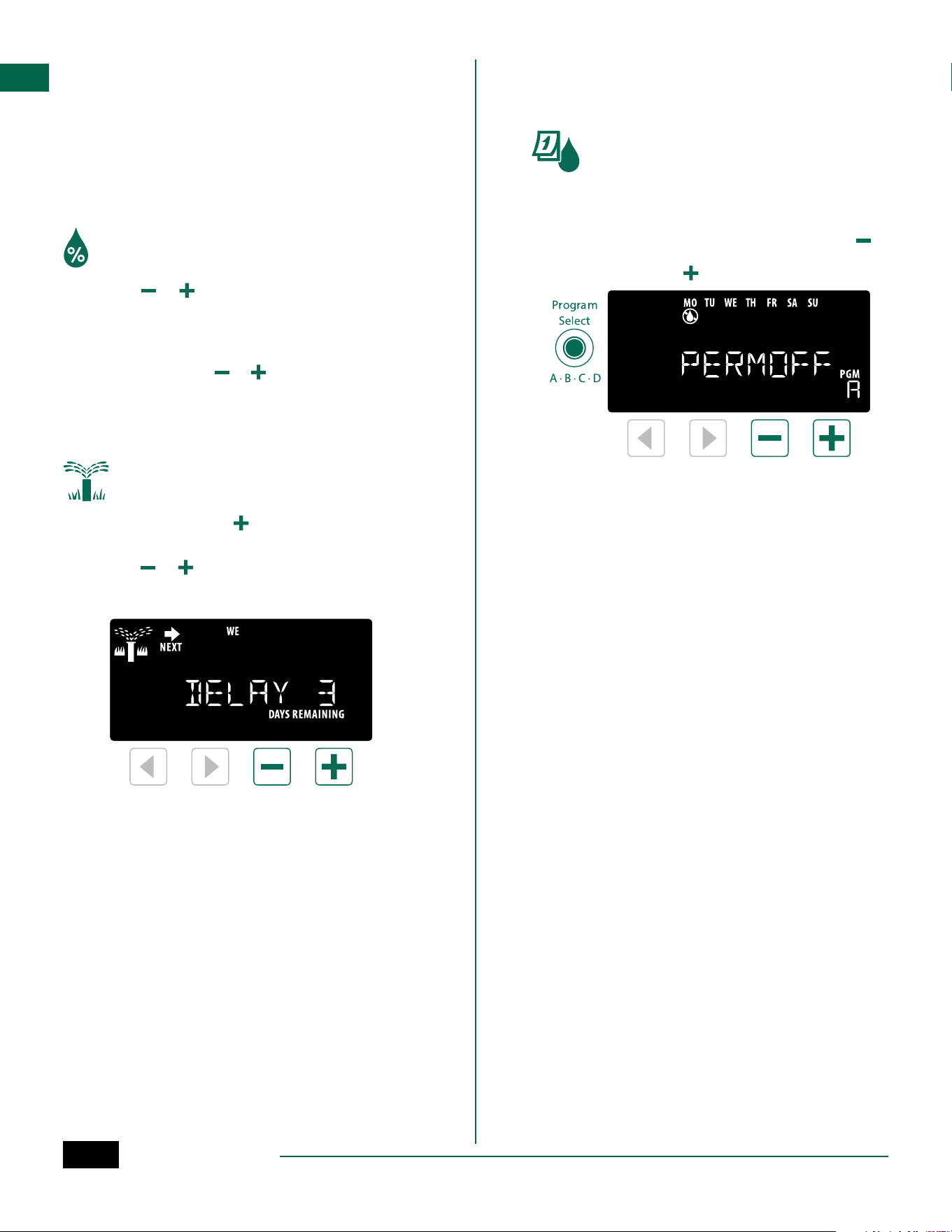
PERMOFF
PERMOFF
Permanent days off
for Odd, Even, Cyclic
watering
RAIN
RAIN Rain Sensor
RESTORD
RESTORD Programming restored
SAVED
SAVED Save programming
SENS ON
SENS ON
Sensor will function if
wired
SEN OFF
SEN OFF
Sensor is ignored even
if wired
SKIP
SKIP
Station not used due to
station module config-
uration
SOAK
SOAK
Soak time between wa-
tering times - support-
ed through the Rain
Bird app.
ESP-ME3 Controller
10
EN
Basic Programming
1. Set Date and Time
Turn the dial to Date / Time
a
Press or to select the setting to change.
b
Press or to change the setting value.
c
Press and hold or to accelerate adjustments.
To change the time format (12 hour or 24 hour):
d
With Day of Month blinking, press .
e
Press or to select the desired time format,
then press to return to the time setting.
2. Set Watering Start Times
Up to six Start Times are available for each program.
Turn the dial to Start Times
a
Press Program Select to choose the desired
Program (if necessary).
b
Press or to select an available Start Time.
c
Press or to set the selected Start Time
(ensure the AM/PM setting is correct).
d
Press to set additional Start Times.
e
To turn off a start time press until 12:00 AM
(00:00 in 24 HR), then press one more time for
OFF.
B
NOTE: The OFF Position for any start time is
between 11:45 PM and 12:00 AM.
3. Set Station Run Times
Run Times can be set from one minute up to six hours.
Turn the dial to Run Times
a
Press Program Select to choose the desired
Program (if necessary).
b
Press or to select a Station.
c
Press or to set the Run Time for the selected
Station.
d
Press to set additional Station Run Times.
B
NOTE: Only assign Run Times in a Program for
stations you want to water. If you do not want a
specific station to run in a selected program then
set the Run Time to zero.
B
NOTE: Rain Bird recommends that the maximum
irrigation station cycle time be less than the time
required for runoff to begin and that there be
adequate soak time before the next irrigation
cycle of that same station begins again.
4. Set Water Days
Custom Days of the Week
Set watering to occur on specific days of the week.
Turn the dial to Water Days
a
Press Program Select to choose the desired
Program (if necessary).
b
Press or to set the selected (blinking) day as
either ON or OFF, and to automatically move to
the next day.
c
Press or at any time to move the cursor to the
previous or next day.
B
NOTE: With Sunday selected, press the button
to enter and activate Cyclic Watering (see the
Advanced Programming section). If this is not
desired, press the button to return to watering
by Custom Days.
ESP-ME3 Controller
11
EN
Program-Based Scheduling
The ESP-ME3 uses a programmed-based scheduling
method to create irrigation schedules. This means all
stations with a run time on the program will run in
numerical order.
Common Programming Error
The most common programming error for any pro-
gram-based controller is to set multiple Program Start
Times that cause watering cycles to repeat.
As an example: Program A has a 1st Start Time set to
run at 8:00 AM. But then a 2nd Start Time has mistak-
enly been set for 8:15 AM, which means that all sta-
tions would water a 2nd time.
In this example, a 3rd Start Time has mistakenly been
set for 8:30 AM. Which means all stations would water
a 3rd time. The desired watering time was 45 minutes,
or 15 minutes per station. The actual is 2 hours and 15
minutes, which is excessive watering!
Incorrect: Multiple Start Times set by mistake
Program
Letter
Program
Watering
Time
Program
Start Time
Station
Number
Station
Watering
Duration
A 1st 8:00 AM
1 15 MIN
2 15 MIN
3 15 MIN
A 2nd 8:15 AM
1 15 MIN
2 15 MIN
3 15 MIN
A 3rd 8:30 AM
1 15 MIN
2 15 MIN
3 15 MIN
Correct: Only one Start Time
Program
Letter
Program
Watering
Time
Program
Start Time
Station
Number
Station
Watering
Duration
A 1st 8:00 AM
1 15 MIN
2 15 MIN
3 15 MIN
4 15 MIN
Manual Watering Options
Test All Stations
Start watering immediately for all programmed
stations.
Turn the dial to Manual Watering
a
Press or to set a Run Time.
b
Press the Hold to Start button.
c
Turn the dial to AUTO after display shows
STARTED.
During Testing:
The display shows a blinking sprinkler symbol, the
active Station Number and the remaining Run Time.
d
To cancel the test, turn the dial to OFF for three
seconds until the screen shows OFF.
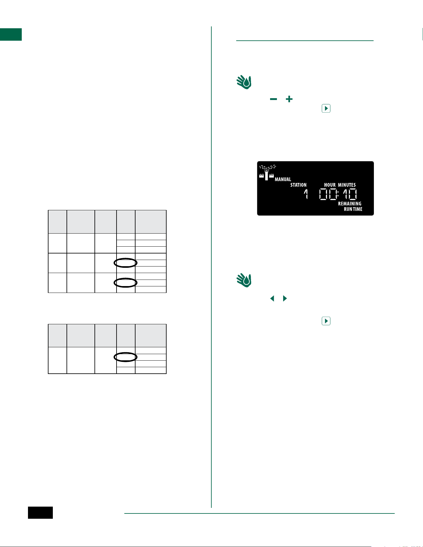
Run a Single Station
Start watering a single station, or set multiple stations
to water in order.
Turn the dial to Manual Watering
a
Press or to select the desired station.
b
Press – or + to set a Run Time.
c
Press the Hold to Start button.
d
Irrigation will begin and STARTED will appear on
the display.
e
Turn the dial back to AUTO
H
REPEAT process as desired to add more stations
to the queue. When one station finishes watering
then the next station will start.
B
NOTE: Manual Watering (Test All, Run Single Sta-
tion and Manual Program) will start even when a
weather sensor is set to SENS ON (sensor on).
ESP-ME3 Controller
12
EN
Run a Single Program
Start watering immediately for one program.
Turn the dial to AUTO.
a
Press Program Select to choose the desired
Program (if necessary).
b
Press the Hold to Start button to begin
watering the selected Program.
c
Irrigation will begin and STARTED will appear on
the display.
d
Press the Advance Station button to advance
to the next station if desired.
e
NOTE: A maximum of 88 stations can be queued
across all four programs.
During Manual Watering (Single-station or Single-program):
The display shows a blinking sprinkler symbol, the
active Station Number, and the remaining Run Time.
• To cancel manual watering, turn the dial to OFF for
three seconds until the screen shows OFF.
To add additional programs to the manual watering queue:
Turn the dial to Manual Watering
a
Press and hold Program Select to show program
letter on the display.
b
Press Program Select to choose the desired
program (if necessary).
c
Press the Hold to Start button to begin watering
the selected program.
d
Turn the dial to AUTO
Advanced Programming
Odd or Even Calendar Days
Set watering to occur on all ODD or EVEN calendar days.
Turn the dial to Water Days
a
Press Program Select to choose the desired
Program (if necessary).
b
Press and hold and until ODD or EVEN is
displayed.
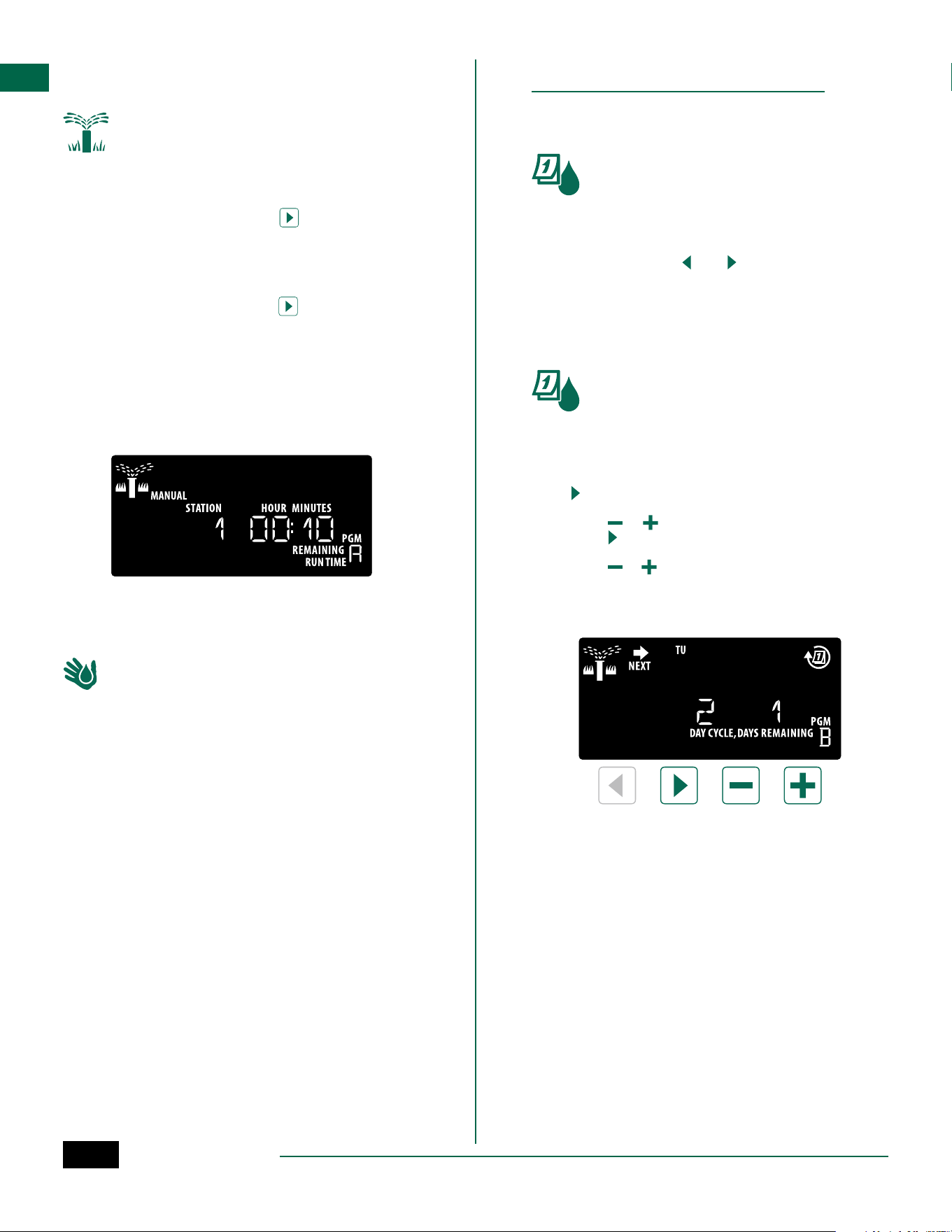
Cyclic Days
Set watering to occur at specific intervals, such as
every 2 days, or every 3 days, etc.
Turn the dial to Water Days
a
Press Program Select to choose the desired
Program (if necessary).
b
On the Custom Days of the Week screen, press
until the Cyclic screen is displayed (after SUN).
c
Press or to set the desired DAY CYCLE, then
press .
d
Press or to set the DAYS REMAINING before
the cycle begins. The NEXT watering day updates
on the display to indicate the day that watering
will start as shown.
B
NOTE: See Special Features to set Rain Sensor
ON by Station.
ESP-ME3 Controller
13
EN
Seasonal Adjust
Increase or decrease program run times by a selected
percentage (5% to 200%).
As an example: If the Seasonal Adjust is set to 100%
and the station Run Time is programmed for 10 min-
utes, the station will run for 10 minutes. If the Seasonal
Adjust is set to 50%, the station will run for 5 minutes.
Turn the dial to Seasonal Adjust.
a
Press or to increase or decrease Seasonal
Adjust for all Programs.
b
To adjust an individual Program, press Program
Select to choose the desired Program (if
necessary). Press or to increase or decrease
Seasonal Adjust for all Programs.
Delay Watering
Suspend watering for up to 14 days.
Turn the dial to AUTO.
a
Press and Hold the button to enter the Rain
Delay screen.
b
Press or to set the DAYS REMAINING. The
NEXT watering day will update on the display to
indicate when watering will resume.
c
To cancel a Rain Delay, set the DAYS REMAINING
back to 0.
B
NOTE: When the delay expires, automatic irriga-
tion resumes as scheduled.
Permanent Days Off
Prevent watering on selected days of the week (for
Odd, Even or Cyclic programming only).
Turn the dial to Water Days
a
Press Program Select to choose the desired
Program (if necessary).
b
Press and hold Program Select, then press to
set the selected (blinking) day as a Permanent
Day Off or press to leave the day ON.
ESP-ME3 Controller
14
EN
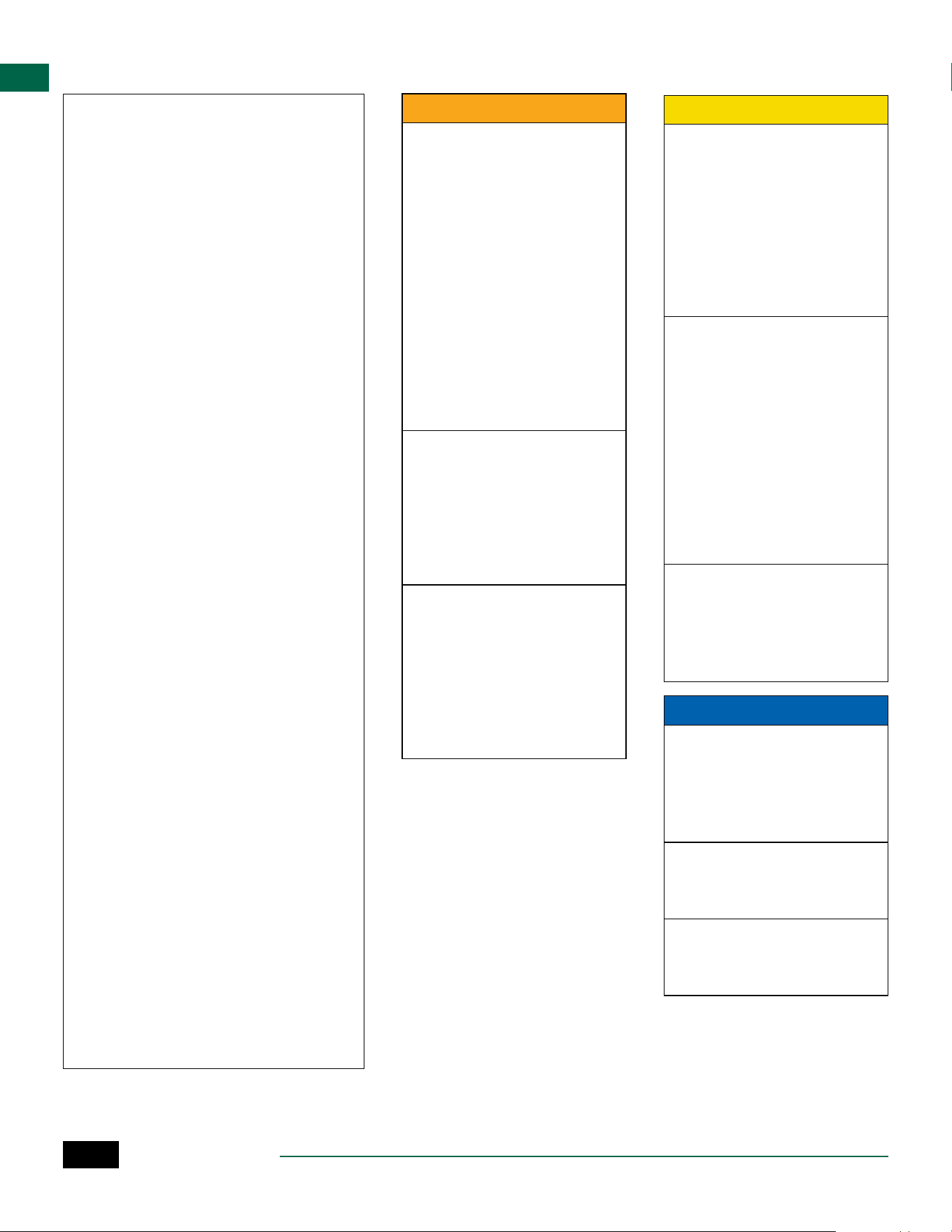
Special Features
a
Turn the dial to the desired position indicated
below for each Special Feature.
b
Press and hold and at the same time.
Set Interstation Delay
by Program
A station delay (from 1
second to 9 hours) ensures
that a valve has completely
closed before the next one
opens. Press Program Select
to set delay for different
programs.
Set Rain Sensor by
Station
Tells a station to obey or
ignore a rain sensor.
Save
Programming
Restore
Programming
Set Master Valve
by Station
Allows a station to be
controlled by a master
valve or pump start relay.
Set to Odd or Even
Watering Days
Options
Reset Button
If the controller is not working properly, you can try
pressing RESET.
• Insert a small tool such as a paper clip, into the
access hole and press until the controller is reset.
All previously programmed watering schedules will
remain stored in memory.
RESET
Remote Accessories
A 5 pin accessory port is available for Rain Bird
approved external devices, including:
• LNK
TM
WiFi Module
• LIMR Receiver Quick Connect harness
PORT
Set Flow Sensor by Station
Turns a flow sensor on or
off by station
Reset to Factory Defaults
All programmed schedules
will be erased.
ESP-ME3 Controller
15
EN
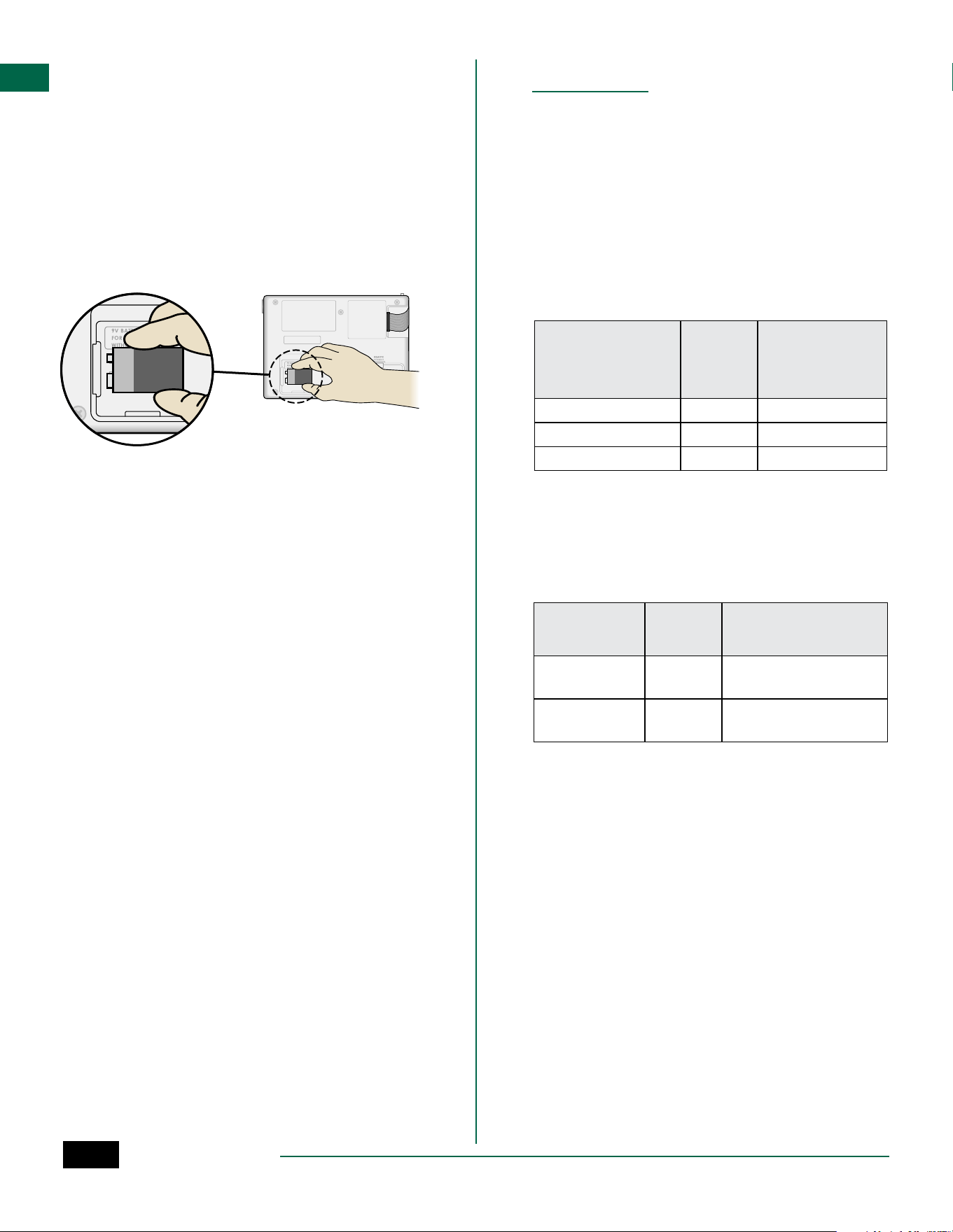
Detached Programming
Program the front panel remotely on battery power.
The front panel can be removed from the controller
and programmed remotely using a 9 volt battery for
power. Settings can be programmed for all 22 stations
regardless of which Station Modules are installed in
the controller.
a
Remove the front panel.
b
Install a 9V battery in the battery compartment.
c
Program the controller.
B
NOTE: Program information is stored in nonvol-
atile memory so it is never lost if the front panel
loses power.
d
Replace the front panel (refer to Complete
Installation in the Installation section).
B
NOTE: After the front panel is re-installed, any
station that does not have a corresponding Sta-
tion Module installed will function as though the
run time is zero.
Battery Life
If the display repeatedly shows “-- -- -- -- --”, or there
is no display when using a 9V battery for remote pro-
gramming, replace the battery.
Appendix
Troubleshooting
Error Detection
The ESP-ME3 controller has built-in error detection
that can automatically generate an ALARM caused by
an essential programming error or if an electrical short
condition is detected.
The ALARM LED light on the ESP-ME3 controller front
panel will light up to indicate an alarm condition:
Programming Errors (blinking LED)
Error
ALARM
LED
Error Mes-
sage On
Display
No Start Times are set BLINK NO START TIMES
No Run Times are set BLINK NO RUN TIMES
No Water Days are set BLINK NO WATER DAYS
The error will go away when the station is successfully
run after condition is corrected.
B
NOTE: The dial must be in the AUTO position for
an ALARM message to appear on the display.
Electrical Errors (non-blinking LED)
Error
ALARM
LED
Error Message
On Display
Master Valve
short
SOLID MASTER VALVE SHORTED
OR HIGH CURRENT
Station short SOLID STATION “X” WIRE SHORT-
ED
When an electrical error is detected, irrigation for the
affected station is cancelled and watering advances to
the next operable station in the program.
The controller will attempt to water the affected sta-
tion again at the next scheduled watering. Completion
of a successful watering will clear the error condition
associated with that station.

ESP-ME3 Controller
16
EN
Watering Issues
Problem Possible Cause Possible Solution
Display shows a
program is active, but
system isn’t watering.
Water source not supplying water. Verify there is no disruption to the main water line and
that all other water supply lines are open and functioning
properly.
Wiring is loose or not properly connect-
ed.
Check that field wiring and master valve or pump start
relay wiring is securely connected at the controller and in
the field.
Field wires are corroded or damaged. Check field wiring for damage and replace if necessary.
Check wiring connections and replace with watertight
splice connectors if needed.
Loss of AC power. When there is a power loss and a 9 volt battery is in-
stalled, the system does not irrigate but programs show
as remaining active.
NO AC message on
display.
No Power detected. Check circuit breaker and that unit is plugged into socket
or properly connected to power source.
Controller may be plugged into a GFCI
outlet or an outlet that is wired to a GFCI
outlet.
Check power to the outlet or reset the circuit breaker.
It just rained and
the alarm light is not
illuminated, why?
This is normal operation. The ESP-ME3
does not consider the interruption of
irrigation due to rainfall as an alarm
condition.
This is normal operation.
Flow Alarms
Error
ALARM
LED
Error Message
On Display
Flow Sensor -
High Flow Con-
dition
Solid HIGH FLOW ALARM STA-
TION "X"
Flow Sensor -
Low Flow Con-
dition
Solid LOW FLOW ALARM STA-
TION "X"
When a flow sensor is in use the ESP-ME3 monitors for
High Flow of 130% above regular learned flow. This
percent limit can be adjusted in the Rain Bird App
when used with LNK
TM
WiFi Module. If a High Flow con-
dition is detected, a “High Flow Alarm” is shown at the
display and the red alarm LED comes on. To clear the
alarm press the “Hold to Start” right arrow button dur-
ing the alarm message.
Low Flow conditions are also monitored. The limit
for Low Flow is 70% below the learned flow unless
changed in the Rain Bird App. A Low Flow alarm is
shown at the controller display and the red alarm LED
comes on.
To clear the alarm press the “Hold to Start” right arrow
button during the alarm message.
B
NOTE: Turning the flow sensor feature off and
then back on will cause the controller to learn
new flow levels and ignore previous error condi-
tions.
B
NOTE: If the flow sensor measures flow when the
controller is not scheduled for watering, a “HIGH
FLOW ZONE” alarm is shown on the display and
the red alarm LED comes on. To clear the alarm
press the “Hold to Start” right arrow button dur-
ing the alarm message.

ESP-ME3 Controller
17
EN
Watering Issues
Problem Possible Cause Possible Solution
Programmed sched-
ules do not start.
Connected rain sensor may be activat-
ed.
Set Rain Sensor to Sensor OFF to ignore the rain sensor.
If watering resumes, the sensor is operating properly and
no further correction is needed.
Connected rain sensor may not be oper-
ating properly.
Let the rain sensor dry out, or disconnect it from the
controller terminal strip and replace it with a jumper wire
connecting the two SENS terminals, or set to Sensor OFF.
If no rain sensor is connected, the
jumper wire connecting the two SENS
terminals on the terminal strip may be
missing or damaged.
Move dial position to Weather Sensors and set to Sensor
OFF.
Too much irrigation Multiple Start Times in the same pro-
gram.
Separate start times are not required for each valve. A
program only requires single start time in order to run all
stations in that program.
Multiple programs are running at the
same time.
Review programming to assure that the same Station is
not active in multiple Programs.
Valve is malfunctioning. Check to see if the ALARM light on the controller is lit
solid, then repair or replace the valve if necessary.
Seasonal Adjust setting is too high. Set Seasonal Adjust to 100%.
Electrical Issues (solid LED illuminated)
Problem Possible Cause Possible Solution
Display is blank or fro-
zen, the controller will
not accept program-
ming or is operating
abnormally.
Power not reaching the
controller.
Verify the main AC power supply is securely plugged in or connect-
ed and working properly.
Controller needs to be reset. Press the Reset Button. For details see “Reset Button” section.
An electrical surge may have
interfered with the control-
ler’s electronics.
Unplug the controller for 2 minutes, then plug it back in. If there is
no permanent damage, the controller should accept programming
and resume normal operation.
Automatic error detec-
tion indicates a problem
by ALARM LED and
an error message on
display.
Short circuit or overload
condition in valve, master
valve or pump start relay
wiring.
Identify and repair the fault in the wiring. Refer to compatible
pump start relays. For details see “Connect Pump Start Relay”
section.
LED is flashing or solidly
illuminated but I see no
message on the LCD.
Dial not in AUTO RUN
position.
Turn dial to AUTO RUN position. Push Reset button or power cycle
the controller.
ESP-ME3 Controller
18
EN
Safety Information
CWARNING
Special precautions must be taken
when valve wires (also known as
station or solenoid wires) are locat-
ed adjacent to, or share a conduit
with other wires, such as those
used for landscape lighting, other
“low voltage” systems or other
“high voltage” power.
Separate and insulate all conduc-
tors carefully, taking care not to
damage wire insulation during
installation. An electrical “short”
(contact) between the valve wires
and another power source can
damage the controller and create a
fire hazard.
All electrical connections and wiring
runs must comply with local build-
ing codes. Some local codes require
that only a licensed or certified
electrician can install power. Only
professional personnel should in-
stall the controller. Check your local
building codes for guidance.
Outdoor controller shall be
permanently connected to fixed
wiring by a flexible cord, and
have a cord anchorage. The cord
anchorage shall relieve conductors
from strain, including twisting,
at the terminals and protect the
insulation of the conductors from
abrasion.
CCAUTION
Stationary appliances not fitted
with means for disconnection from
the supply mains having a contact
separation in all poles that provide
full disconnection under overvolt-
age category III, the instructions
state that means for disconnection
must be incorporated in the fixed
wiring in accordance with the
wiring rules
This appliance can be used by chil-
dren aged from 8 years and above
and persons with reduced physical,
sensory or mental capabilities or
lack of experience and knowledge
if they have been given supervision
or instruction concerning use of
the appliance in a safe way and
understand the hazards involved.
Children shall not play with the
appliance. Cleaning and user
maintenance shall not be made by
children without supervision.
For controllers not provided
with supply cord, the fixed
installation must include a dis-
connecting device for all three
poles suitable for overvoltage
category III protection.
NOTICE
Use only Rain Bird approved
accessory devices. Unapproved
devices may damage the controller
and void the warranty. For a list of
compatible devices go to: www.
rainbird.com
Changes or modifications not ex-
pressly approved by Rain Bird could
void the user’s authority to operate
the equipment.
Date and time are retained by a
lithium battery which must be
disposed of in accordance with local
regulations.
Certifications
Supplier’s Declaration of Conformity
47 CFR § 2.1077 Compliance Information
Unique Identifier: ESP-ME3 (ESP4ME3)
Responsible Party – U.S. Contact
Information
Rain Bird Corporation
9491 Ridgehaven Court
San Diego, CA
92123
Ph. (858) 268-2650
FCC Compliance Statement
This device complies with Part 15 of the FCC
Rules. Operation is subject to the following two
conditions: (1) This device may not cause harm-
ful interference, and (2) this device must accept
any interference received, including interfer-
ence that may cause undesired operation.
Note: This equipment has been tested and
found to comply with the limits for a Class B dig-
ital device, pursuant to part 15 of the FCC Rules.
These limits are designed to provide reasonable
protection against harmful interference in a res-
idential installation. This equipment generates,
uses and can radiate radio frequency energy
and, if not installed and used in accordance with
the instructions, may cause harmful interfer-
ence to radio communications. However, there
is no guarantee that interference will not occur
in a particular installation. If this equipment
does cause harmful interference to radio or
television reception, which can be determined
by turning the equipment off and on, the user is
encouraged to try to correct the interference by
one or more of the following measures:
• Reorient or relocate the receiving antenna.
• Increase the separation between the equip-
ment and receiver.
• Connect the equipment into an outlet on a
circuit different from that to which the receiver
is connected.
• Consult the dealer or an experienced radio/TV
technician for help.
• Changes or modifications not expressly
approved by Rain Bird could void the user’s
authority to operate the equipment.
ICES-003 Compliance Label/Étiquette de
conformité à la NMB-003
CAN ICES-3(B)/NMB-3(B)

The Intelligent Use of Water®
LEADERSHIP · EDUCATION · PARTNERSHIPS · PRODUCTS
At Rain Bird, we believe it is our responsibility to develop
products and technologies that use water efficiently. Our
commitment also extends to education, training and
services for our industry and community.
The need to conserve water has never been greater.
We want to do even more and with your help we can.
Visit www.rainbird.com for more information about The
Intelligent Use of Water®.
Rain Bird Corporation
6991 East Southpoint Road
Tucson, AZ 85756
USA
Tel: (520) 741-6100
Rain Bird Turkey
Çamlık Mh. Dinç Sokak Sk. No.4 D:59-60
34760 Ümraniye, İstanbul
TÜRKIYE
Tel: (90) 216 443 75 23
www.rainbird.com.tr
Rain Bird Ibérica S.A.
C/ Valentín Beato, 22 2ª Izq. fdo
28037 Madrid
ESPAÑA
Tel: (34) 91 632 48 10
[email protected] · www.rainbird.es
www.rainbird.pt
Rain Bird Corporation
970 W. Sierra Madre Ave.
Azusa, CA 91702
USA
Tel: (626) 812-3400
Rain Bird Europe SNC
Rain Bird France SNC
240 rue René Descartes
Bâtiment A, parc Le Clamar
BP 40072
13792 AIX-EN-PROVENCE CEDEX 3
FRANCE
Tel: (33) 4 42 24 44 61
[email protected] · www.rainbird.eu
[email protected] · www.rainbird.fr
Rain Bird Australia Pty Ltd.
Unit 13, Level1
85 Mt Derrimut Road
PO Box 183
Deer Park, VIC 3023
Tel: 1800 724 624
[email protected].com.au
www.rainbird.com/au
Technical Services for
U.S. and Canada only:
1 (800) RAINBIRD
1-800-247-3782
www.rainbird.com
Rain Bird International
1000 W. Sierra Madre Ave.
Azusa, CA 91702
USA
Tel: +1 (626) 963-9311
Rain Bird Deutschland GmbH
Königstraße 10c
70173 Stuttgart
DEUTSCHLAND
Tel: +49 (0) 711 222 54 158
Rain Bird Brasil Ltda.
Rua Marques Póvoa, 215
Bairro Osvaldo Rezende
Uberlândia, MG, Brasil
CEP 38.400-438
Tel: 55 (34) 3221-8210
www.rainbird.com.br
)
Registered trademark of Rain Bird Corporation
(
2020 Rain Bird Corporation D41274 15JA20