ASSEMBLY AND USER’S GUIDE
SKU: 75207
DE FILTER REPLACEMENT GRID SET
75208
FITS
60
FT DE FILTER
75207
SKU: 75208
FITS 48 FT DE FILTER
Read all safety warnings and instructions. Failure to follow the
warnings and instructions may result in serious injury. Save all
warnings and instructions for future reference.
DANGER

THIS PAGE INTENTIONALLY LEFT BLANK

TABLE OF CONTENTS
1
18DISCLAIMER
INTRODUCTION
5ASSEMBLY INSTRUCTIONS
5ASSEMBLY
4
3PACKAGING CONTENTS
3PRODUCT INFORMATION
2
Legends and Symbols
2IMPORTANT SAFETY INSTRUCTIONS
1TABLE OF CONTENTS
18Customer Service
18Disclaimer
5Step 2: Backwash Filter
5Step 1: Verify Grid Size
6Step 4: Drain Tank
6Step 3: Open Air Relief Valve
7Step 6: Detach Clamp Assembly
7Step 5: Power Shutdown
9Step 8: Extract Grid Assembly
8Step 7: Lift Tank Lid
11Step 10: Inspect and Select Grids
10Step 9: Disassemble Grid Assembly
12Step 12: Assemble New Grids
11Step 11: Clean Tank
13Step 14: Insert Tie Rod
13Step 13: Install Grid Retainer
14Step 16: Fasten Tie Rod
14Step 15: Position Grid Assembly Upright
15Step 17: Position New Grid Assembly
16Step 19: Attach Clamp Assembly
15Step 18: Place Tank Lid
17Step 21: Leak Testing
17Step 20: Attach Drain Plug
CUSTOMER SERVICE
If you have any questions about ordering our pool pumps and replacement parts or pool products,
please feel free to contact us using the following contact information:
Customer Service and Technical Support
Phone: (909) 628-0880
Email: [email protected]
Hours of Operation: Monday – Friday, 9AM – 4PM (CST)
IMPORTANT SAFETY INSTRUCTIONS
2
For safety reasons, children should not be allowed to use this product.
Packing materials and plastic bags are not toys. Keep them away from children to prevent the risk
of suffocation.
Failure to comply with all instructions and warnings may lead to severe bodily
injury or even death. For optimal safety and functionality, it is advisable to have the product installed
and serviced by a certified service professional. Prior to using this product, installers, operators, and
owners must carefully review these warnings and all instructions provided in the owner's manual. It
is essential to leave these warnings and the owner's manual with the owner for their reference and
safety.
ATTENTION INSTALLER: This manual contains vital information regarding the installation,
operation, and safe use of this product. It is essential to provide this manual to the end user of the
product. Failure to read and follow all instructions could lead to severe injuries.
USE OF NON-XTREMEPOWERUS REPLACEMENT PARTS VOIDS WARRANTY
DANGER: Ignoring these hazards can result in death, severe personal injury, or
significant property damage.
WARNING: Indicates potential hazards that can result in severe personal injury,
death, or significant property damage. Ignoring these warnings presents a real
danger.
CAUTION: Indicates potential hazards that can result in minor or moderate
personal injury, property damage, or actions that are unpredictable and unsafe.
Ignoring these cautions presents a potential hazard.
NOTICE: This label indicates important special instructions that are not directly
related to hazards.
This guide provides instructions for installing and using the DE FILTER REPLACEMENT GRID
SET. If you have any questions about the equipment, please contact XtremepowerUS.
This guide contains important information about safely installing and operating this product. After
installation, make sure to share this information with the owner/operator or leave it with them for
their reference.
Legends and Symbols
When you come across the safety-alert symbol on your equipment or in this manual, pay attention
to the following signal words and remain vigilant about the potential for personal injury.
IMPORTANT SAFETY INSTRUCTIONS
DANGER
WARNING
WARNING
CAUTION
NOTE
DANGER
3
PRODUCT INFORMATION
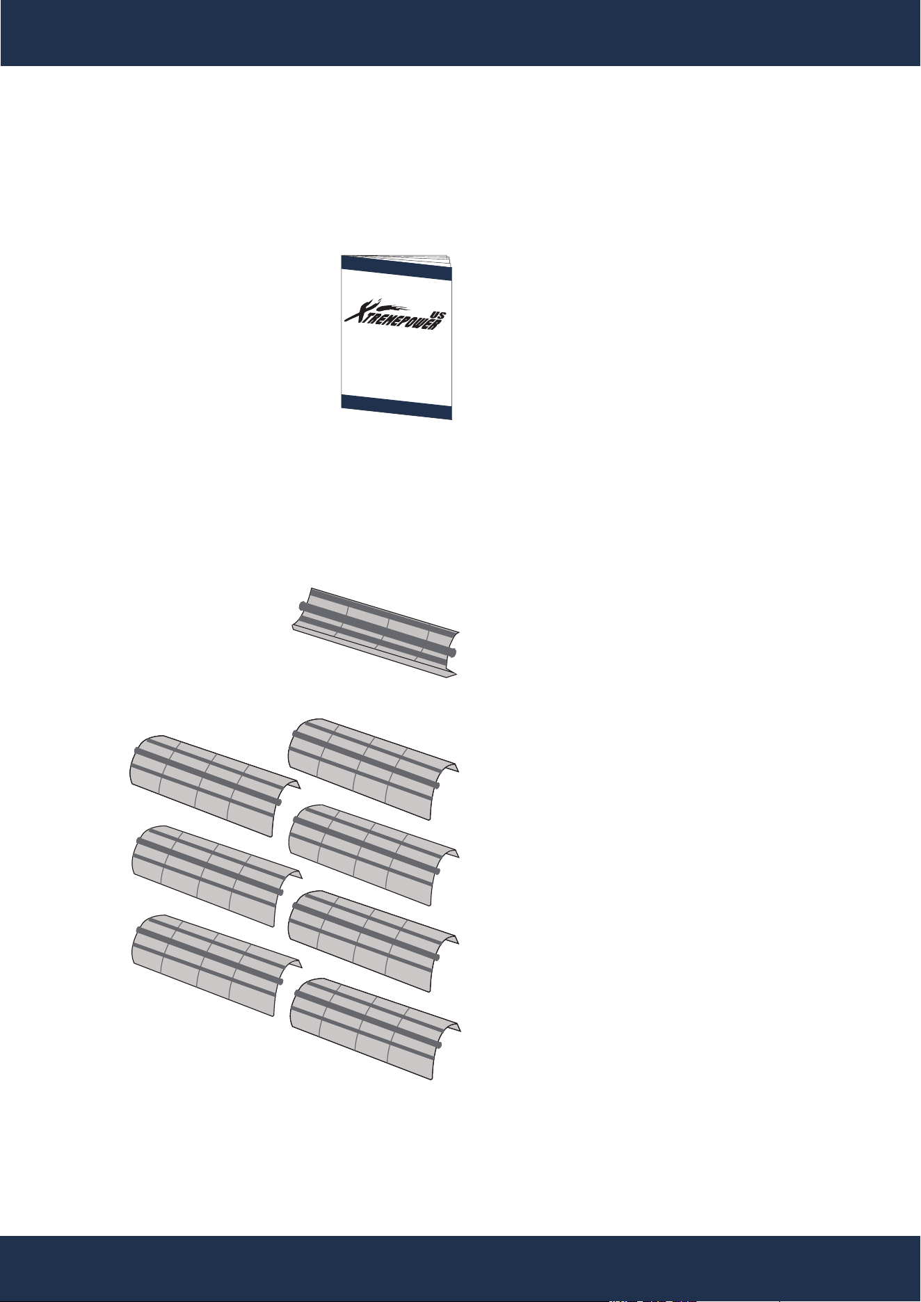
PACKAGING CONTENTS
PRODUCT INFORMATION
PARTS # 2
LARGE REPLACEMENT GRID
7 PC(S)
PARTS # 1
SMALL REPLACEMENT GRID
1 PC(S)
INSTRUCTION MANUAL
1 PC(S)
SKU 75207 / SKU 75208

PRODUCT INFORMATION
4
XtremepowerUS D.E. Filter Replacement Grid Set – The optimal choice for main-
taining crystal-clear pool water. This replacement grid set is engineered to pro-
vide superior filtration, ensuring that every swim is in clean and pure water.
Crafted with high-quality materials, this replacement grid is designed for seamless integration
with D.E. filter systems, making installation straightforward and hassle-free. Its robust con-
struction reduces the need for frequent replacements while improving filtration performance.
The unique design of the D.E. Filter Replacement Grid maximizes the filtration area, allowing
for the most efficient capture of dirt and debris. This results in less maintenance and more
time for enjoyment. It's not just a replacement; it's an upgrade to pool cleanliness and peace
of mind.
With the XtremepowerUS D.E. Filter Replacement Grid, expect:
• Enhanced filtration for water that sparkles with cleanliness.
• Easy installation with a perfect fit for D.E. filter systems.
• Durable construction that withstands regular use.
• Cost-effective maintenance due to long-lasting materials.
INTRODUCTION
PRODUCT INFORMATION
ASSEMBLY
5
ASSEMBLY
ASSEMBLY INSTRUCTIONS
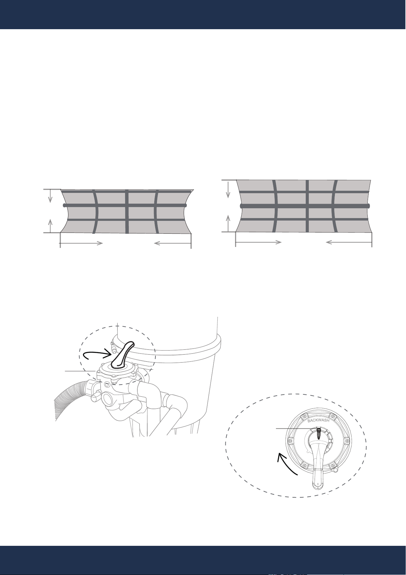
Step 1: Verify Grid Size
Verify that the replacement grids’ size matches the original ones from the filter.
WIDTH
HEIGHT
WIDTH
HEIGHT
Step 2: Backwash Filter
Perform a backwash to remove old D.E. and debris, facilitating a cleaner grid change.
THE REGULAR GRID FROM THE SET
THE SMALL GRID FROM THE SET
BACKWASH
ROTATE
CLOCKWISE
ROTATE
CLOCKWISE
VALVE
PARTS # 1
PARTS # 2
ASSEMBLY
6
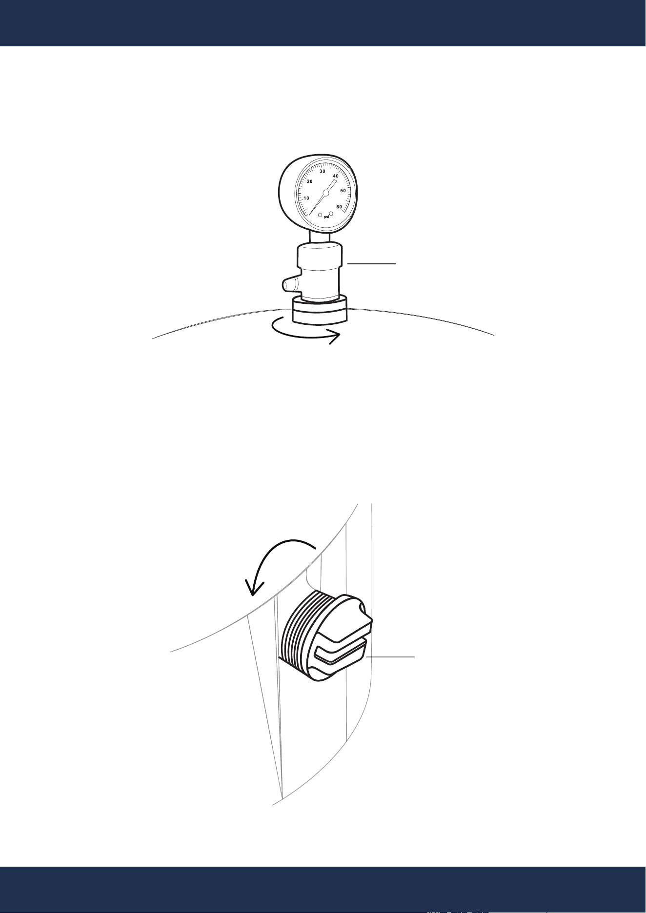
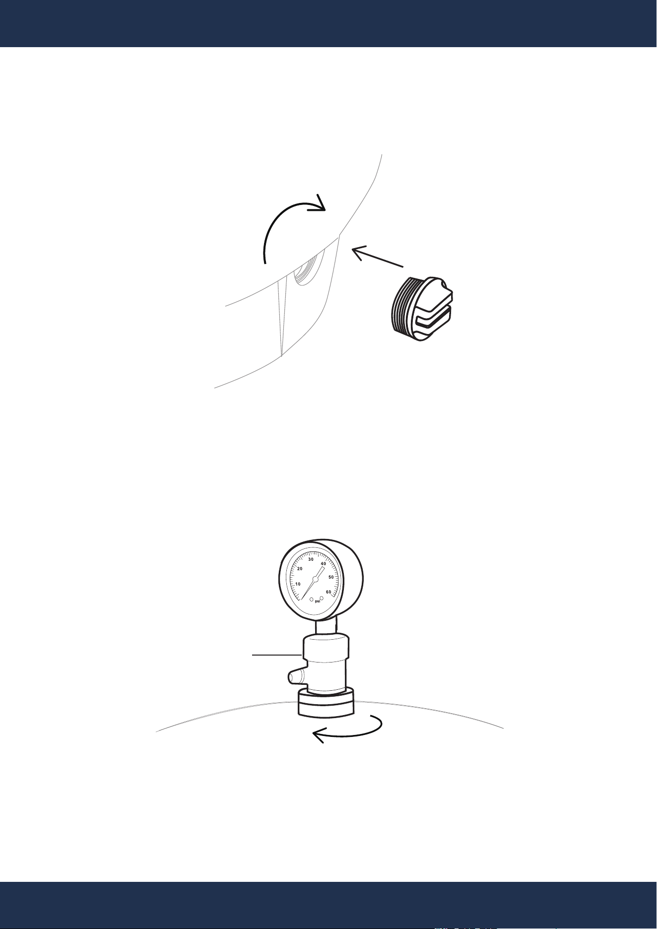
Step 3: Open Air Relief Valve
Flush out water from filter’s tank and plumbing by opening the filter’s pressure gauge or valve.
ROTATE
COUNTERCLOCKWISE
Step 4: Drain Tank
Remove the filter’s drain cap for water evacuation.
ROTATE
COUNTERCLOCKWISE
GAUGE
DRAIN CAP
7
ASSEMBLY
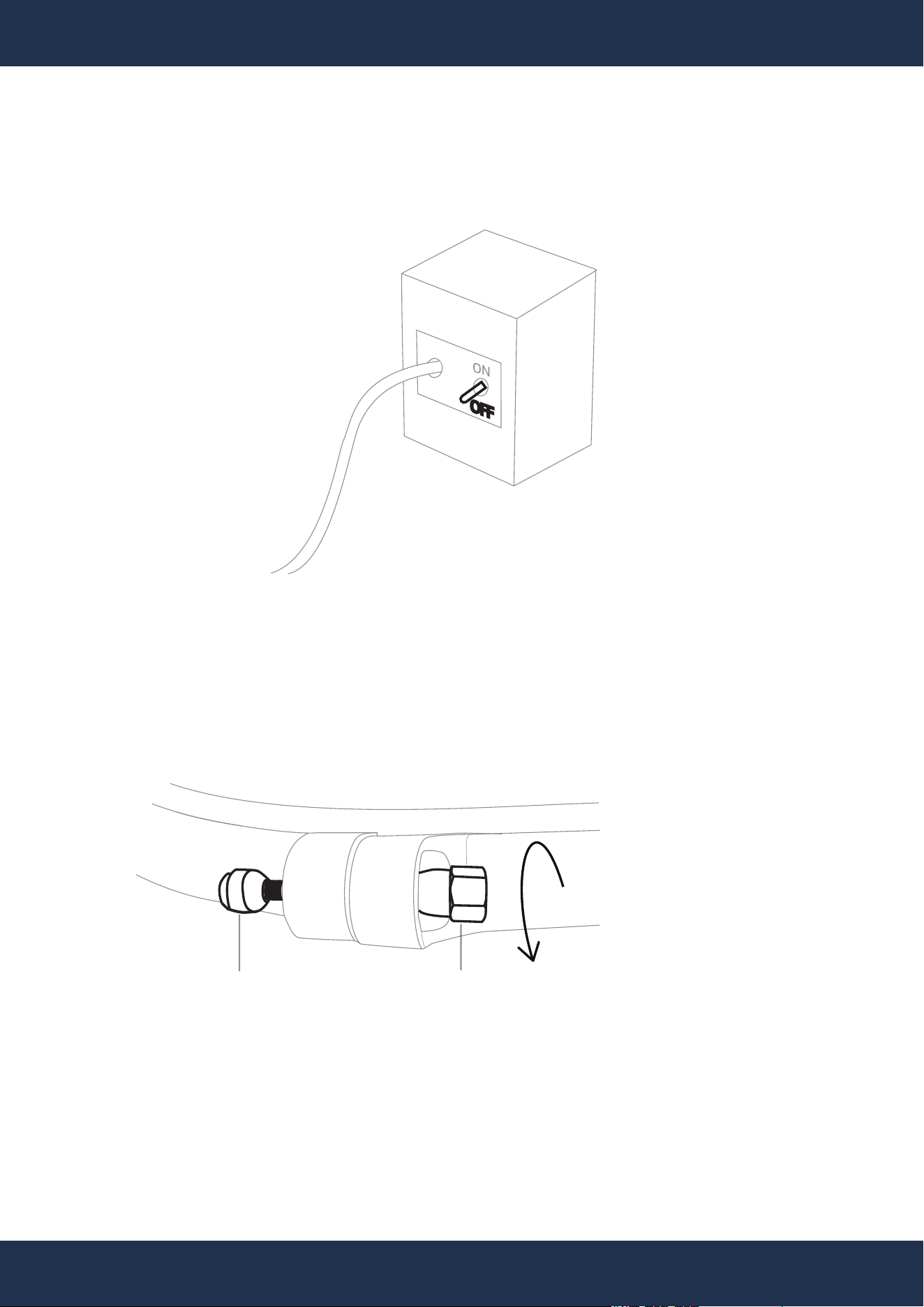
Step 5: Power Shutdown
Ensure all equipments' power is disconnected at the breaker.
Step 6: Detach Clamp Assembly
Remove the bolt and nut from the filter’s clamp assembly, then remove the whole clamp.
ROTATE
COUNTERCLOCKWISE
CLAMP
ASSEMBLY BOLT
CLAMP
ASSEMBLY NUT
8
ASSEMBLY
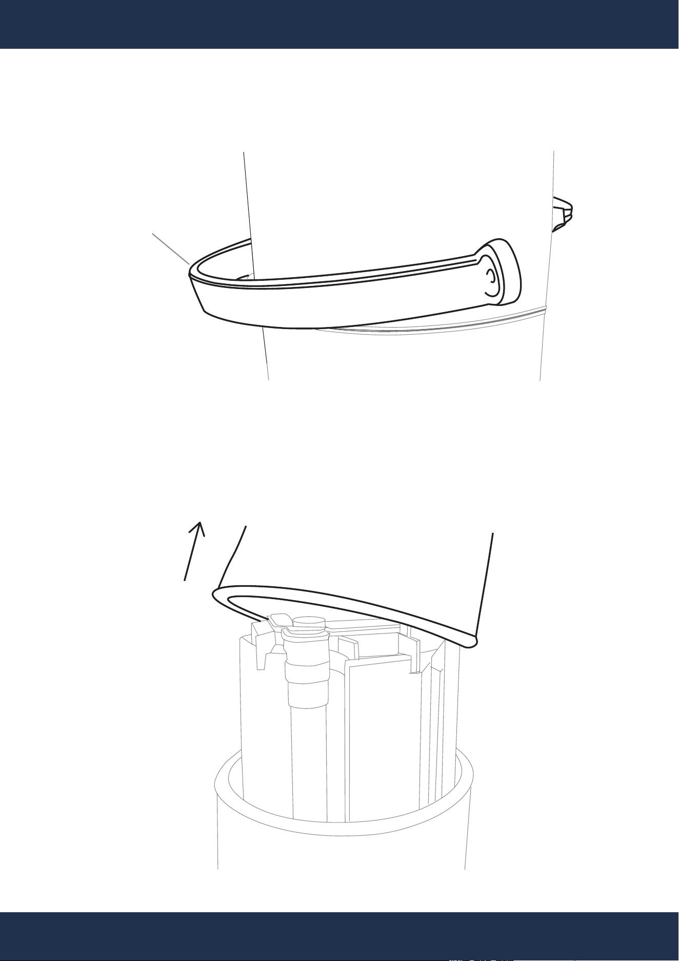
Step 7: Lift Tank Lid
Remove the upper filter body and set it aside for reinstallation late.
Step 6: Continue to Detach Clamp Assembly
CLAMP ASSEMBLY
UPPER FILTER BODY
LOWER FILTER BODY
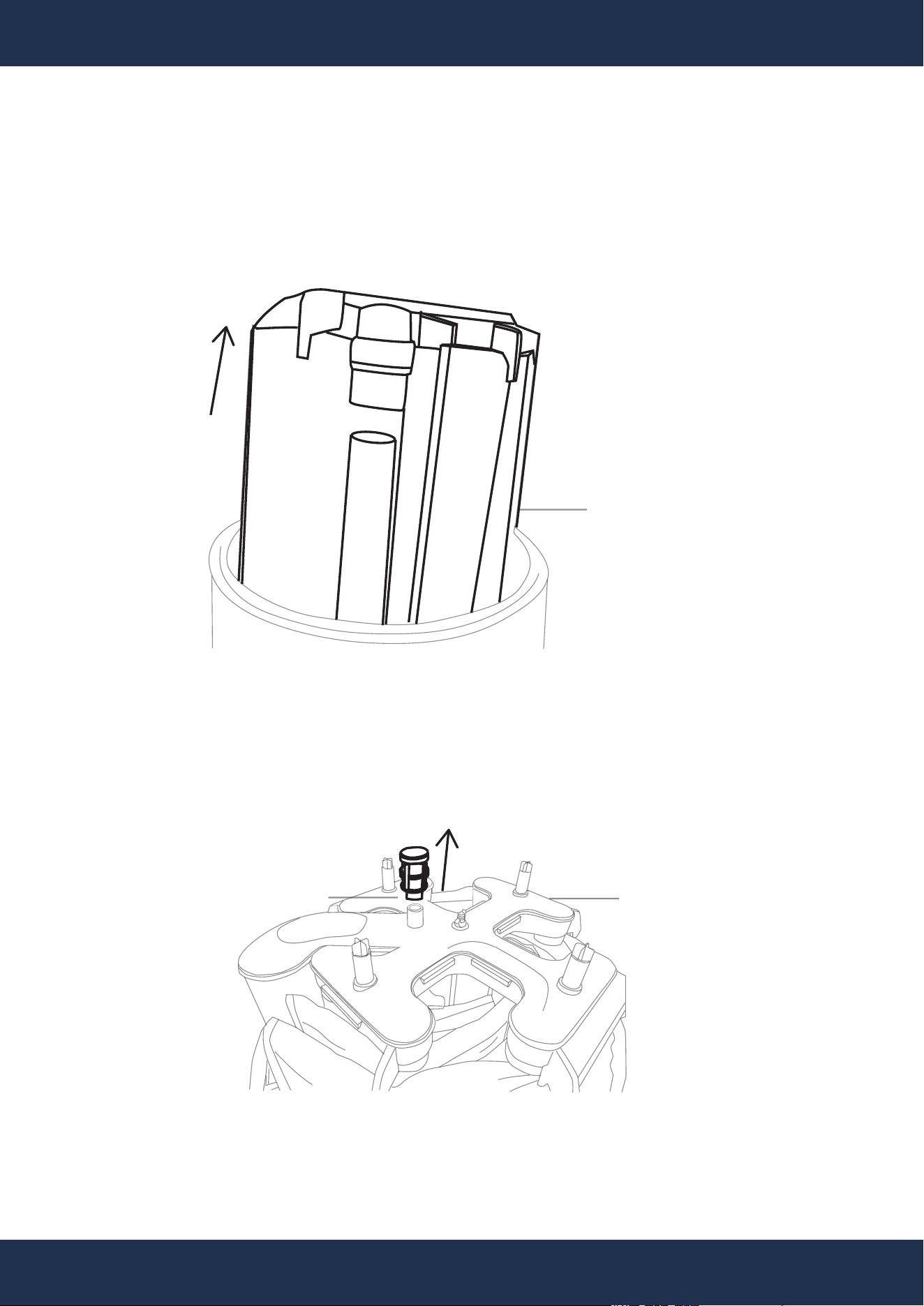
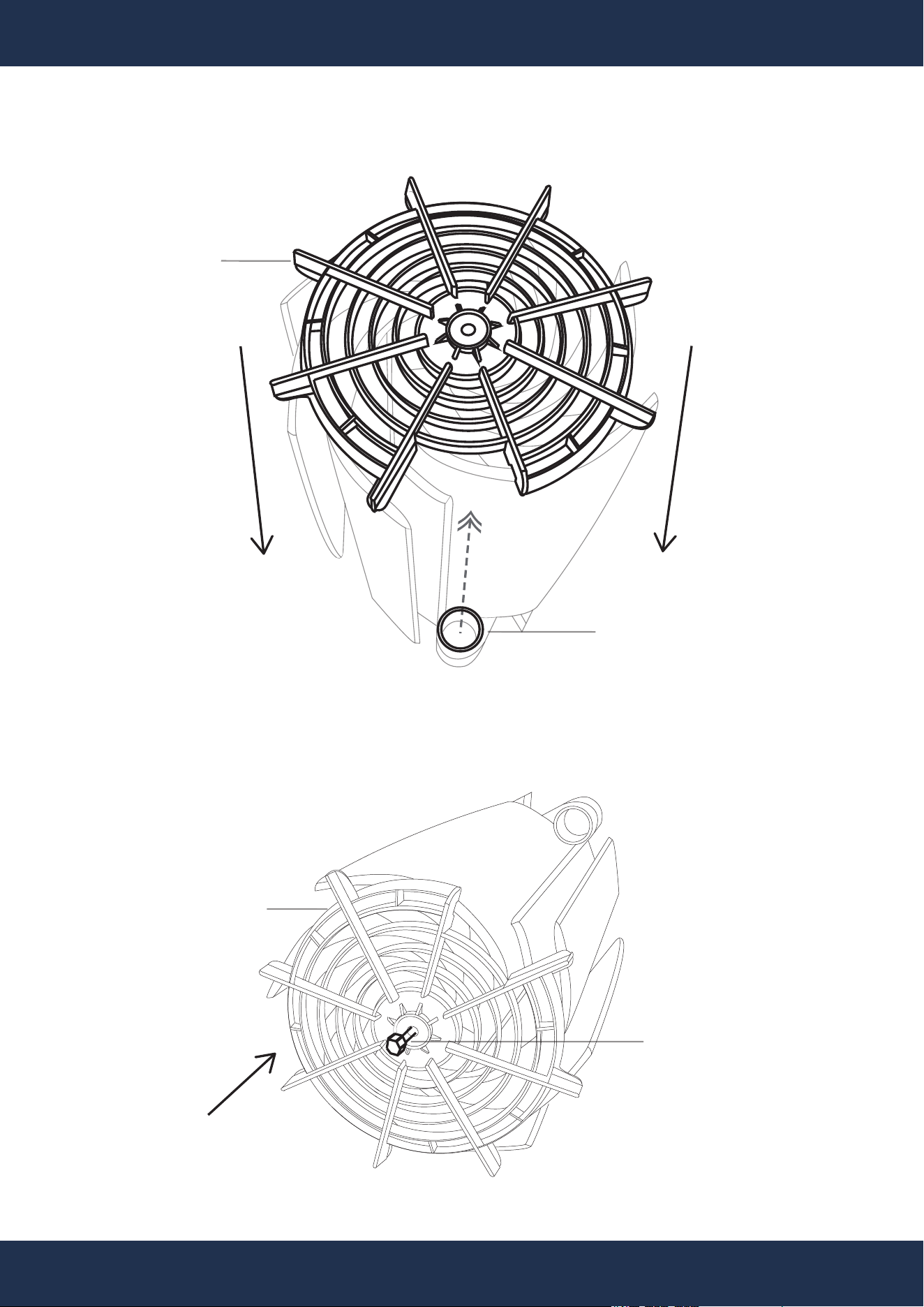
Step 8: Extract Grid Assembly
Lift the grid assembly from filter’s tank. Detach the manifold cap from the top of manifold.
9
ASSEMBLY
TOP GRID RETAINER SIDE
TOP MANIFOLD SIDE
MANIFOLD CAP
GRID
ASSEMBLY
MANIFOLD
LOWER FILTER BODY
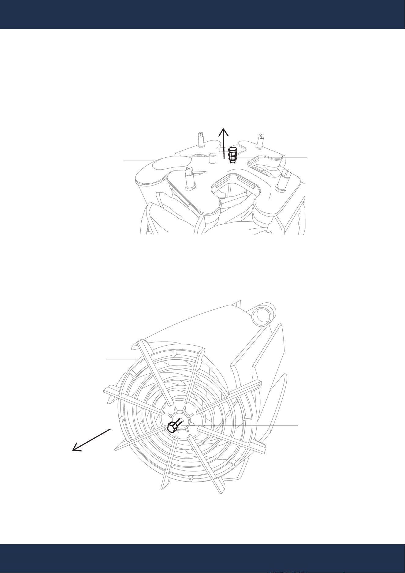
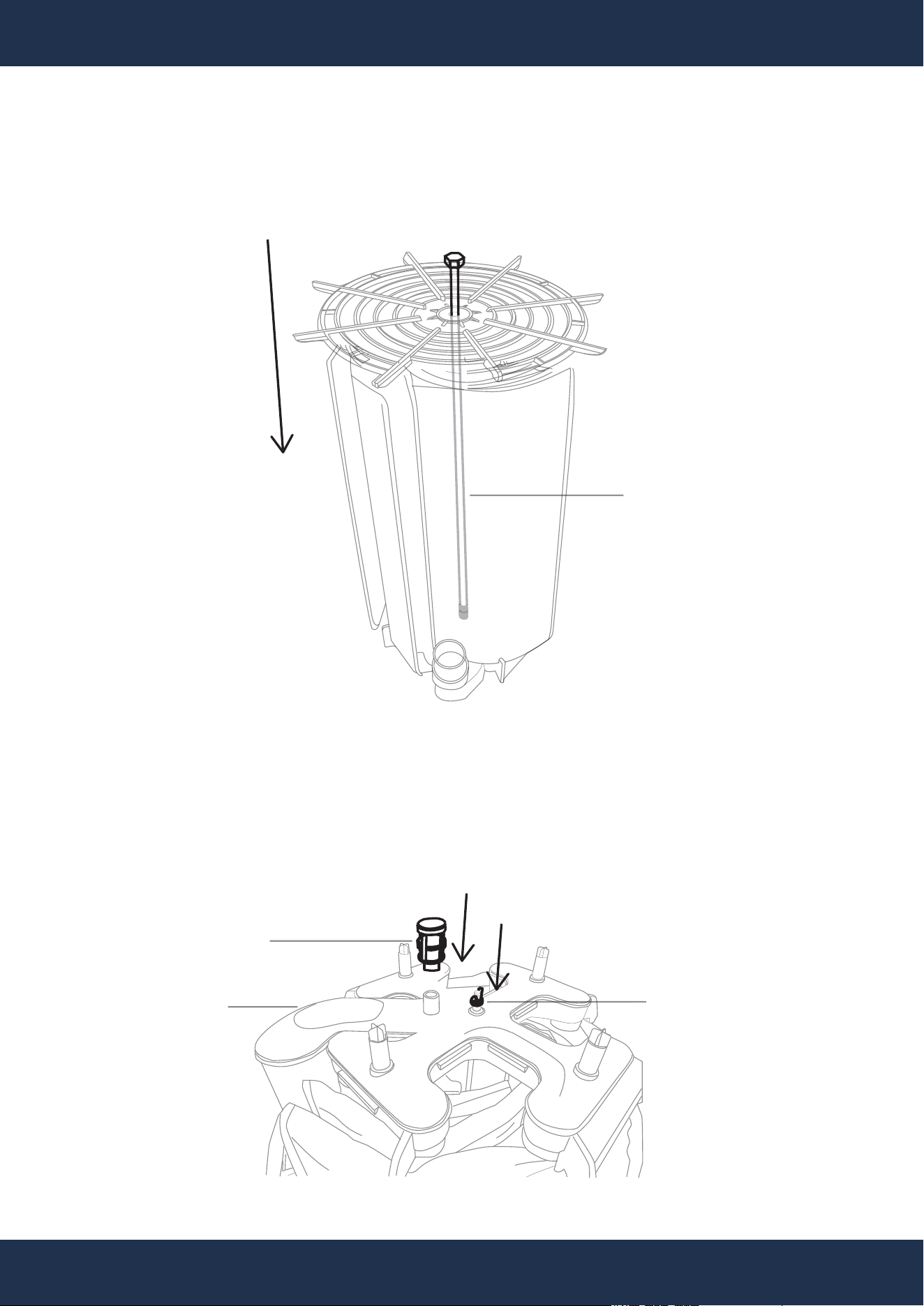
Step 9: Disassemble Grid Assembly
Detach the manifold from the tie rod by unscrewing the securing nut, preparing for individual grid
inspection or replacement.
10
ASSEMBLY
TOP MANIFOLD SIDE
NUT
MANIFOLD
TIE ROD
SCREW
BOTTOM GRID RETAINER SIDE
TOP MANIFOLD SIDE
GRID RETAINER
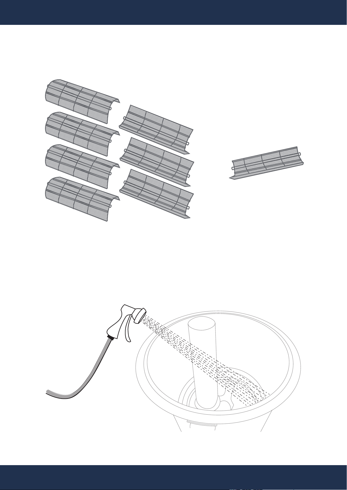
Step 10: Inspect and Select Grids
Evaluate grids for damage, removing only those necessary or replace the entire set as needed.
11
ASSEMBLY
Step 11: Clean Tank
Wash out any residual D.E. powder or debris, ensuring the lower filter body and gasket
grooves are clean.
ONE SMALL GRID
SEVEN LARGE GRID(S)
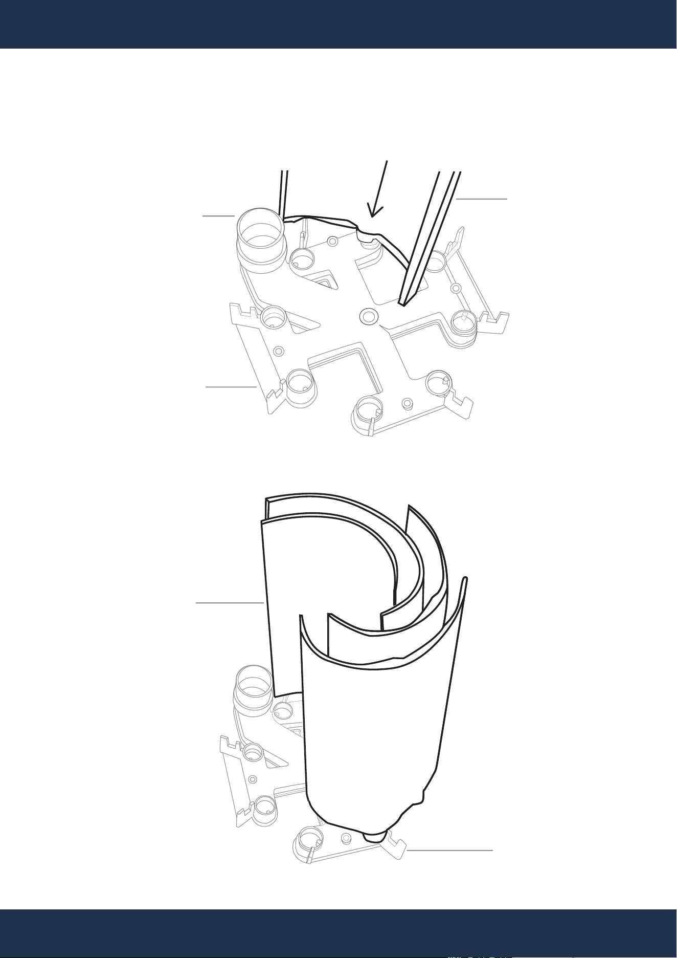
Step 12: Assemble New Grids
Place the manifold on a stable surface, then sequentially install grids into the manifold, starting
with the smaller grid at the standpipe port.
12
ASSEMBLY
SMALL GRID
STANDPIPE PORT
SMALL GRID
MANIFOLD
MANIFOLD
Step 13: Install Grid Retainer
Align the grid retainer and top standpipe manifold port, ensuring correct grid placement.
13
ASSEMBLY
Step 14: Insert Tie Rod
Insert the tie rod through the retainer and manifold.
GRID RETAINER
STANDPIPE MANIFOLD PORT
TIE ROD (SCREW)
BOTTOM GRID RETAINER SIDE
TOP MANIFOLD SIDE
GRID RETAINER
14
ASSEMBLY
Step 16: Fasten Tie Rod
Attach the tie rod nut to secure the manifold at the assembly's top. Attach the manifold cap to
the top of manifold.
TOP MANIFOLD SIDE
THE TIE ROD NUT
MANIFOLD
Step 15: Position Grid Assembly Upright
Flip the grid assembly to an upright position, ensuring both the retainer and manifold are held
securely.
TIE ROD (SCREW)
BOTTOM GRID RETAINER SIDE
TOP MANIFOLD SIDE
MANIFOLD CAP
15
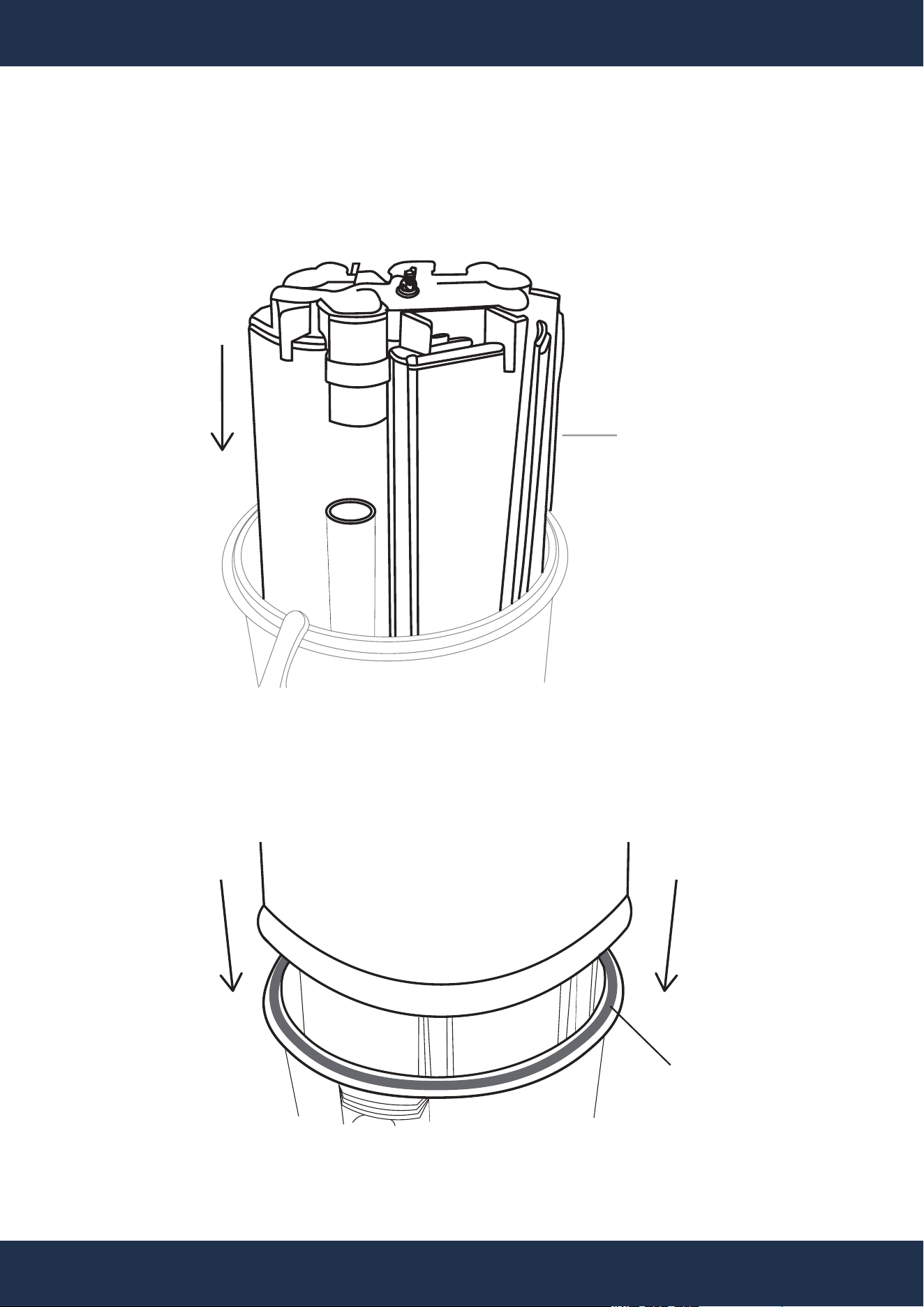
Step 17: Position New Grid Assembly
Align and install the grid assembly within the lower filter body, ensuring proper standpipe align-
ment, then reassemble the manifold cap onto the top of manifold.
ASSEMBLY
TOP MANIFOLD SIDE
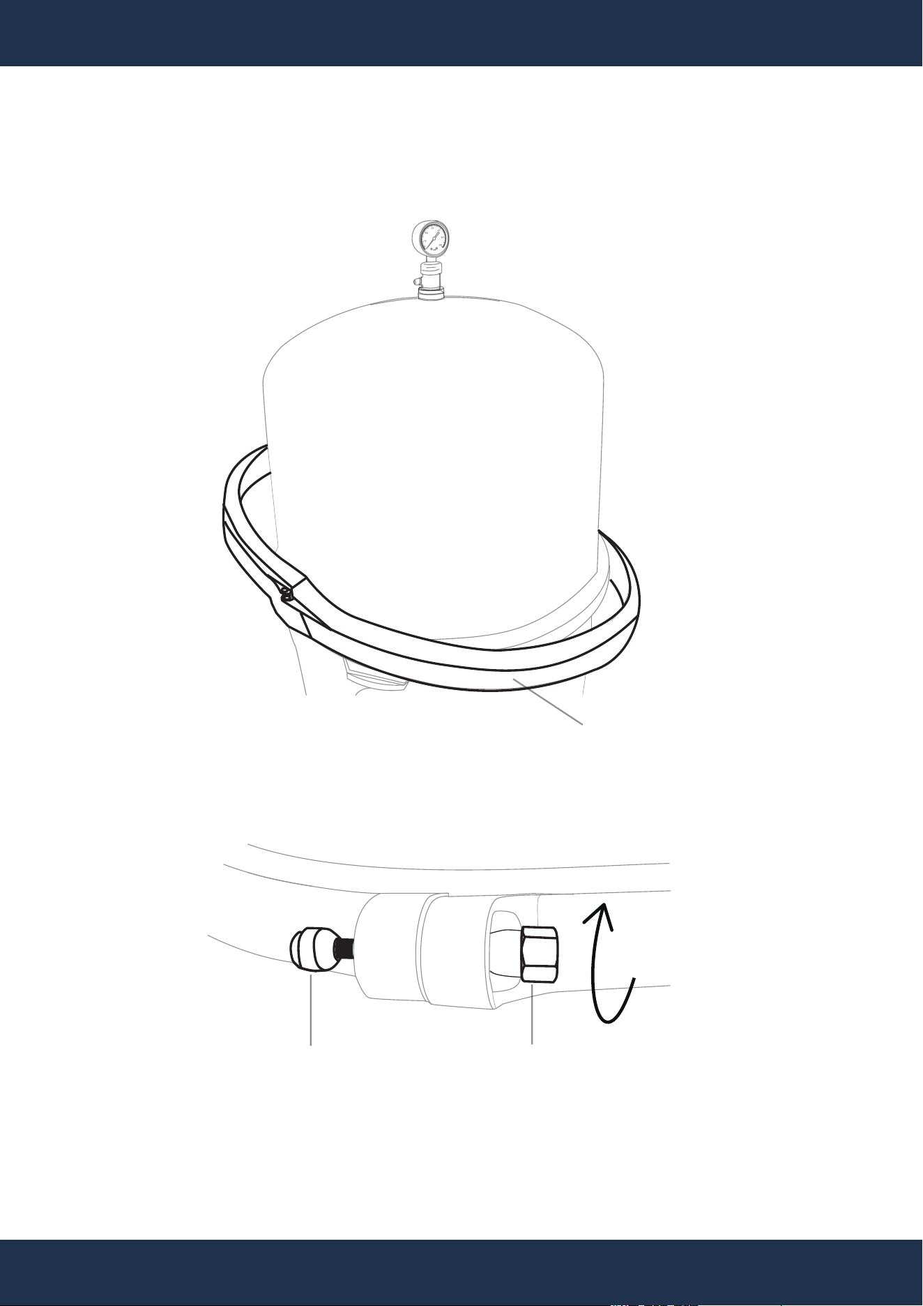
Step 18: Place Tank Lid
Reattach the upper filter body, maintaining the o-ring in its designated groove.
GRID
ASSEMBLY
LOWER FILTER BODY
UPPER FILTER BODY
O-RING
LOWER FILTER BODY
ASSEMBLY
16
Step 19: Attach Clamp Assembly
Evenly position the clamp assembly, and securely fasten the bolt and nut.
CLAMP ASSEMBLY
ROTATE
CLOCKWISE
CLAMP
ASSEMBLY BOLT
CLAMP
ASSEMBLY NUT
ASSEMBLY
17
Step 20: Attach Drain Plug
Secure the filter’s drain plug.
ROTATE
CLOCKWISE
Step 21: Leak Testing
Fasten and secure the filter’s pressure gauge or valve. Activate the pump for priming,
checking for leaks and ensuring proper seal alignment if leaks are present.
ROTATE
CLOCKWISE
GAUGE

18
DISCLAIMER
DISCLAIMER
PLEASE READ THE FOLLOWING CAREFULLY
The manufacturer and/or distributor have provided the parts list and assembly diagram in this
manual for reference purposes only. They do not make any representation or warranty to the buyer
that they are qualified to make repairs to the product or replace any parts of the product. In fact, the
manufacturer and/or distributor expressly state that all repairs and parts replacements should be
undertaken by certified and licensed technicians, and not by the buyer.
The buyer assumes all risk and liability arising from their repairs to the original product or
replacement parts or arising from their installation of replacement parts. It is strongly advised that
qualified professionals handle any repairs or replacements to ensure safety and proper functioning
of the product. Improper installation and operation may result in injury, property damage, or voiding
of warranty. The manufacturer and/or distributor shall not be held responsible for any accidents,
damages, or malfunctions resulting from the buyer's installation and operation of the product. It is
essential to follow all safety guidelines and recommendations provided in this manual and to seek
professional assistance if unsure about the installation or operation procedures.
CUSTOMER SERVICE
If you have any questions about ordering our pool pumps and replacement parts or pool products,
please feel free to contact us using the following contact information:
Customer Service and Technical Support
Phone: (909) 628-0880
Email: [email protected]
Hours of Operation: Monday – Friday, 9AM – 4PM (CST)
