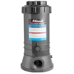
ASSEMBLY AND USER’S GUIDE
IMPORTANT:
Review the instruction manual thoroughly before operating the machine.
Keep it for future reference.
SKU: 90156AUTOMATIC CHLORINE FEEDER
OFFLINE WITH CONTROL VALVE
90156


TABLE OF CONTENTS
1
TABLE OF CONTENTS
IMPORTANT SAFETY INSTRUCTIONS
OVERVIEW (PRODUCT INFORMATION)
PRODUCT OVERVIEW
INSTALLATION
SET-UP FOR INSTALLATION
CHLORINE FEEDER CONNECTION
OPERATION
GENERAL USAGE
REFILL INSTRUCTIONS
REPLACEMENT PARTS 9
Disclainmer
Legends and Symbols
DISCLAIMER 10
1
10
2
2
4
4
5
5
5
Customer Service and Technical Support
10
PRODUCT INTRODUCTION
4
7
O-RING REPLACEMENT
8
FLOW CONTROL VALVE HANDLE REMOVAL
8
7
7
WINTERIZING
VACUUMING
LUBRICATION
8
8
8
PLUMBING LINE CONNECTION
6
MAINTENANCE
8
PARTS DIAGRAM
9
IMPORTANT SAFETY INSTRUCTIONS
2
For safety reasons, children should not be allowed to use this product.
Packing materials and plastic bags are not toys. Keep them away from children to prevent the risk
of suffocation.
Failure to comply with all instructions and warnings may lead to severe bodily
injury or even death. For optimal safety and functionality, it is advisable to have the product installed
and serviced by a certified service professional. Prior to using this product, installers, operators, and
owners must carefully review these warnings and all instructions provided in the owner's manual. It
is essential to leave these warnings and the owner's manual with the owner for their reference and
safety.
ATTENTION INSTALLER: This manual contains vital information regarding the installation,
operation, and safe use of this product. It is essential to provide this manual to the end user of the
product. Failure to read and follow all instructions could lead to severe injuries.
USE OF NON-XTREMEPOWERUS REPLACEMENT PARTS VOIDS WARRANTY
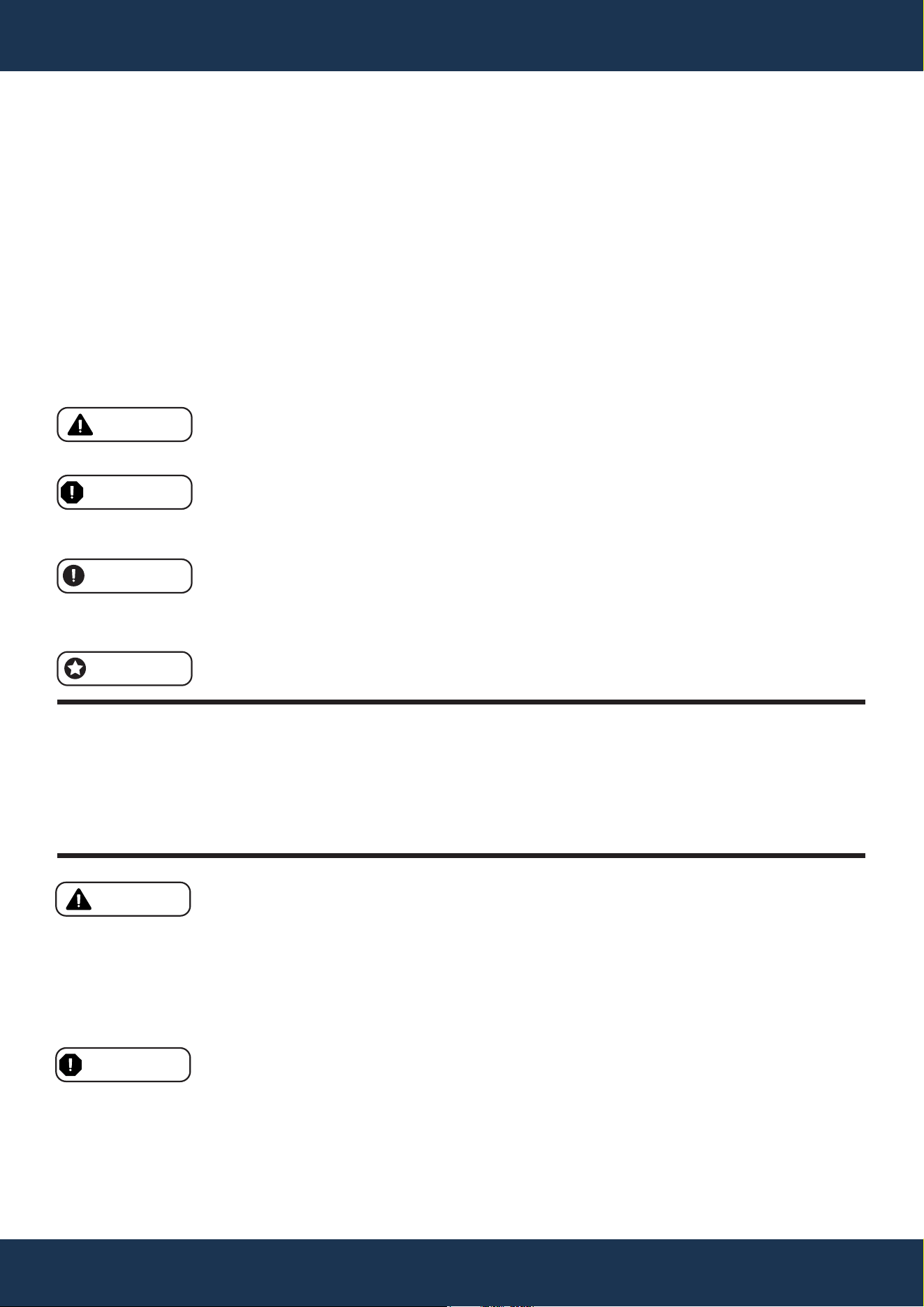
DANGER: Ignoring these hazards can result in death, severe personal injury, or
significant property damage.
WARNING: Indicates potential hazards that can result in severe personal injury,
death, or significant property damage. Ignoring these warnings presents a real
danger.
CAUTION: Indicates potential hazards that can result in minor or moderate
personal injury, property damage, or actions that are unpredictable and unsafe.
Ignoring these cautions presents a potential hazard.
NOTICE: This label indicates important special instructions that are not directly
related to hazards.
This guide provides instructions for installing and using the SPA AUTOMATIC CHLORINE
FEEDER. If you have any questions about the equipment, please contact XtremepowerUS.
This guide contains important information about safely installing and operating this product. After
installation, make sure to share this information with the owner/operator or leave it with them for
their reference.
Legends and Symbols
When you come across the safety-alert symbol on your equipment or in this manual, pay attention
to the following signal words and remain vigilant about the potential for personal injury.
IMPORTANT SAFETY INSTRUCTIONS
DANGER
WARNING
WARNING
CAUTION
NOTE
DANGER
IMPORTANT SAFETY INSTRUCTIONS
3
• Improper Use: Misusing this equipment or not following instructions can cause serious harm or
damage.
• Chemical Mixing: Never mix different chemicals in the feeder.
DANGER
WARNING
CAUTION
• Chlorine Levels: Do not exceed recommended chlorine levels.
• Stable Setup: Install the feeder on a stable surface.
• Regular Checks: Inspect and maintain regularly according to the manual.
NOTE
• Read First: Review the manual thoroughly before use.
• Ventilation: Install in a ventilated area.
• Proper Connection: Ensure correct installation with the pool system.
• Storage: Keep chlorine in a cool, dry place, away from children and pets.
• Emergency Plan: Be aware of emergency procedures.
• Strongly Advised: Ensure individuals are properly trained before operating or servicing this
equipment.
• Personal Protection: Always use protective gear when handling chemicals.
OVERVIEW (PRODUCT INFORMATION)
4
OVERVIEW (PRODUCT INFORMATION)
PRODUCT INTRODUCTION
XtremepowerUS Automatic Chlorine Feeder with Flow Control Valve is the perfect addition to any
pool maintenance setup. Engineered for efficiency and ease of use, it boasts a substantial 9 lbs
capacity, reducing the need for frequent chlorine top-ups. The precision of the integrated flow
control valve ensures the right amount of chlorine is released, keeping pool water pristine and
swim-ready.
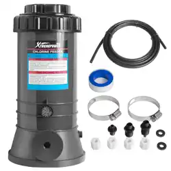
The Auto Off-Line Chlorine Feeder is designed for straightforward installation and effortless
operation. It comes with all the necessary accessories, allowing for immediate setup and integration
into existing pool systems. With this Chlorine Feeder, consistent water quality is seamlessly
maintained, streamlining pool care and ensuring a superior swimming experience without the
constant need for manual chlorine adjustment.
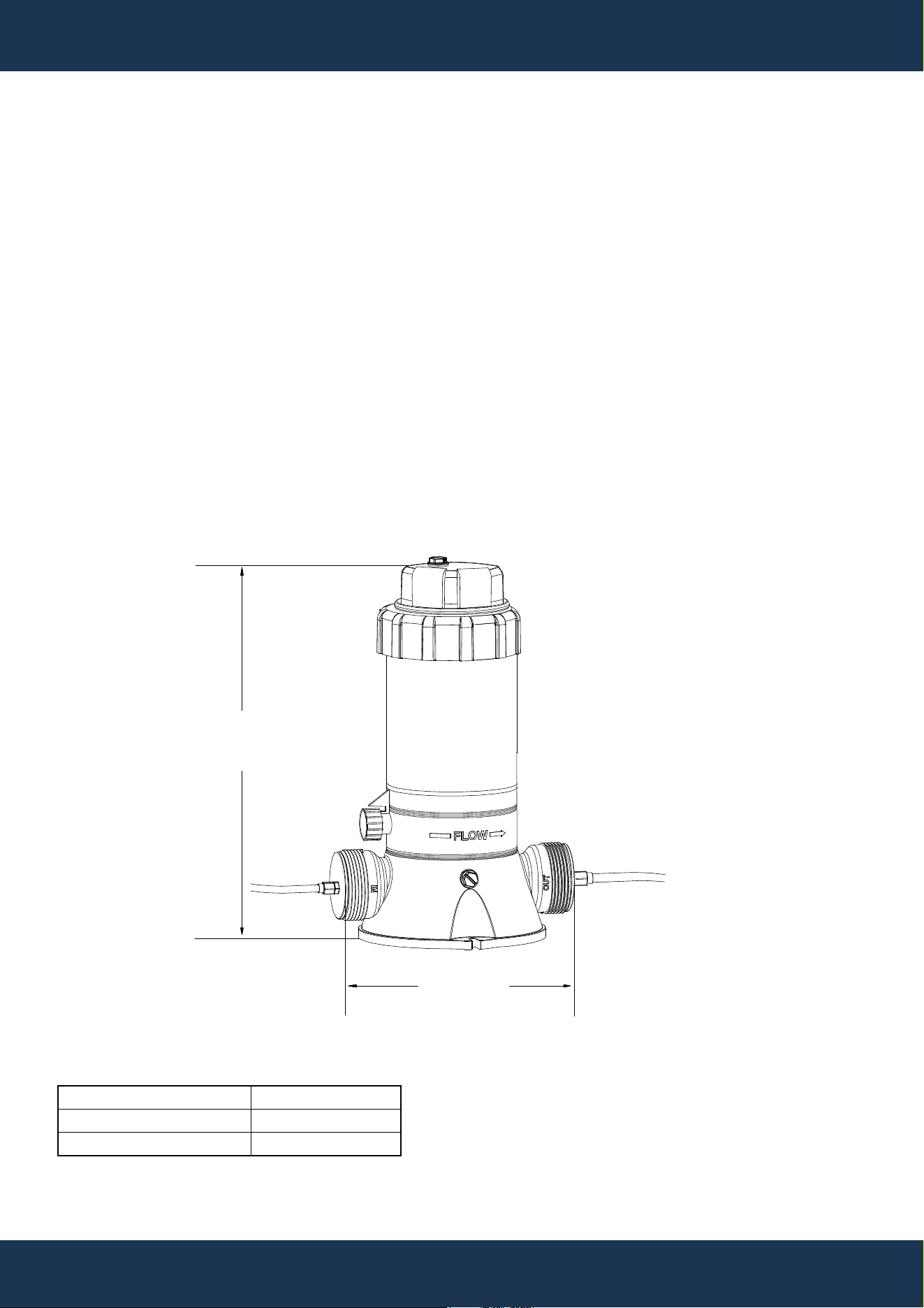
PRODUCT OVERVIEW
15.20”
9.02”
SPECIFICATION
CAPACITY
MAX. PRESSURE
MAX. OUTPUT
9 LBS
50 PSI
32 LBS / HR
INSTALLATION
5
INSTALLATION
SET-UP FOR INSTALLATION
• Mark the pipe for the inlet connection downstream from the PUMP and upstream from the
FILTER.
• Mark the pipe for the outlet connection downstream from the HEATER, or if there is no HEATER,
downstream from the FILTER.
• Cut the tubing to the appropriate lengths based on the marked locations, ensuring ends are
clean and even.
NOTE
Installation directly into copper plumbing is prohibited to prevent pipe damage. Systems with
brass, bronze, or other metal components require a consultation with a professional for specific
installation advice.
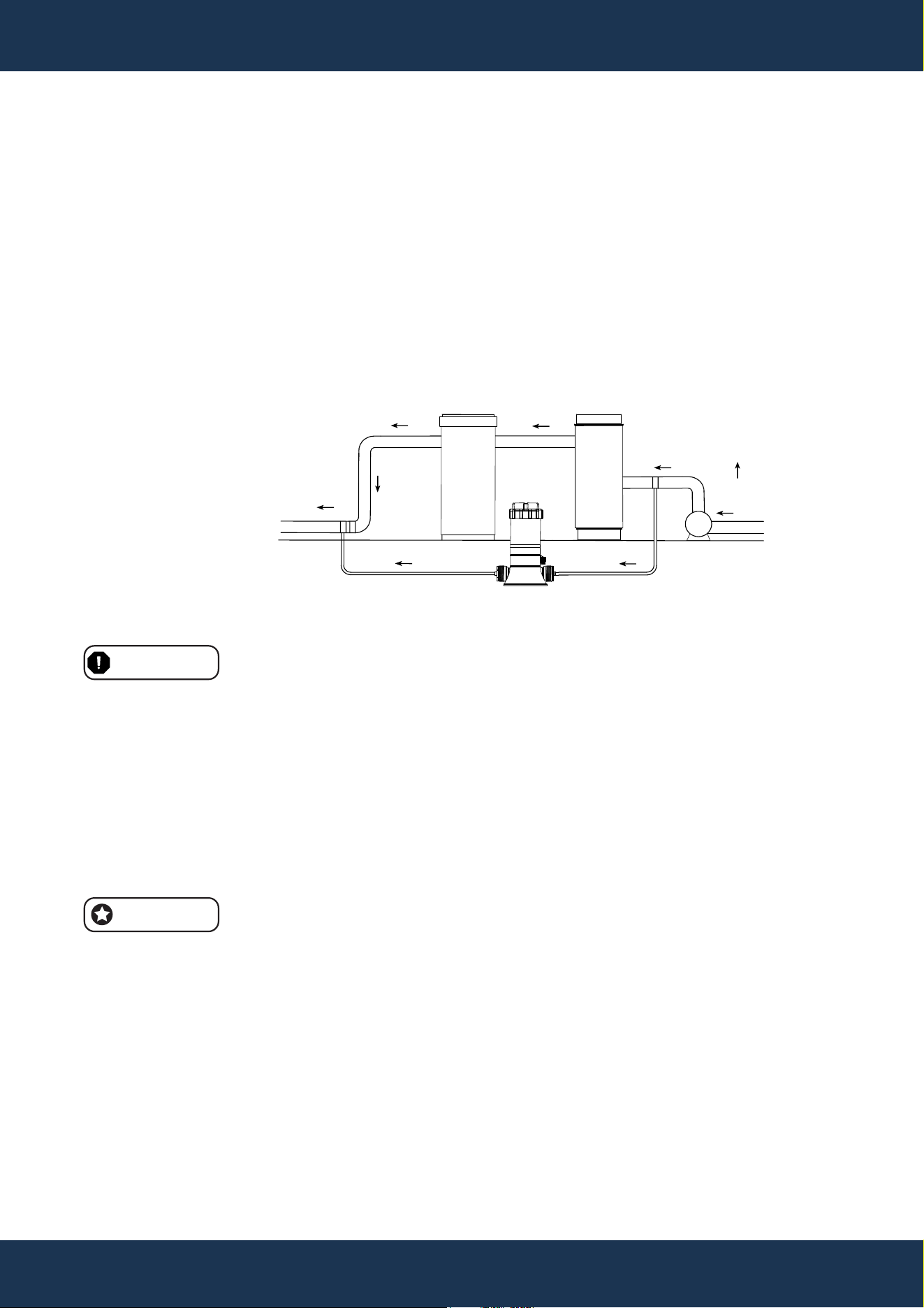
CHLORINE FEEDER CONNECTION
• Apply Teflon tape to the Check Valve's larger male thread and fasten securely to the Chlorine
Feeder's outlet.
FILTERHEATER
PUMP
CHLORINE FEEDER
FROM POOL
UNRESTRICTED
RETURN TO POOL
INLET
OUTLET
FIGURE INSTALLATION & PIPING LAYOUT
WARNING
Identify the Check Valve by the 'dot' marking and the clicking sound of the internal ball when
shaken.
• Apply Teflon tape to the Check Valve's larger male thread and fasten securely to the Chlorine
Feeder's outlet.
• Attach the inlet Fitting Adapter to the Chlorine Feeder's inlet with Teflon tape on its thread.
• For the inlet tubing, slide on a compression nut, insert tubing into the adapter fully, and tighten
by hand to a secure fit without over-tightening.
• Attach the outlet tubing to the Check Valve as done with the inlet tubing.
INSTALLATION
6
PLUMBING LINE CONNECTION
• At the marked inlet point, drill a 3/8" hole and remove any burrs or shavings.
• Place the Saddle Fitting with its gasket into the hole and fasten with the clamp, ensuring a tight
seal without over-tightening.
• Repeat the fitting installation for the outlet using the same steps as the inlet.
• Connect the inlet and outlet tubing to the Saddle Fittings using Compression Nuts and secure
without excessive force.
NOTE
Saddle Fittings and clamps are intended for 1 1/2” or 2” outer diameter pipes.
After system activation, examine all connections for leaks and adjust if necessary to maintain a
leak-free system.
WARNING

7
OPERATION
REFILL INSTRUCTIONS
• Turn off all pumps and timers.
• Set the Chlorine Feeder's flow control valve to the "OFF" position.
• Ensure the return line to the pool from the Chlorine Feeder is free of obstructions.
• Wait one minute after turning off the system to allow for pressure release.
• Carefully remove the Chlorine Feeder cover.
• Restock the Chlorine Feeder exclusively with 3-inch slow-dissolving Trichloro-S-Triazinetrione
Chlorine Tablets.
• Reattach and secure the Chlorine Feeder cover.
• Adjust the flow control valve to the required setting and reactivate the pump.
GENERAL USAGE
• Balance and condition pool/spa water before Chlorine Feeder use.
• Maintain chlorine residual between 1.0 to 1.5 ppm.
• Monitor and adjust chlorine daily via the dial valve.
• Account for varying chlorine demand due to usage, temperature, and sunlight.
• Initially, determine proper chlorine amount and valve settings through trial.
• Follow chemical manufacturer’s instructions for chlorine levels.
OPERATION
DANGER
WARNING
• Only utilize 3-inch diameter slow-dissolving Trichloro-S-Triazinetrione Chlorine tablets.
• Fast-dissolving tablets of the same compound must not be used.
• Mixing chemicals can lead to fire or explosion.
• Avoid combining Trichloro-S-Triazinetrione Chlorine Tablets with Calcium Hypochlorite or any
concentrated chlorine forms or chemicals.
• Do not introduce other chlorine types, pH adjusters, shock treatments, or algaecides into the
skimmer. If necessary, apply these products directly to the pool water.
• Do not block the chlorine feeder with valves or other devices.
• Follow all provided Safety Instructions when operating or servicing the Chlorine Feeder.
• To prevent injury, children should not use this product.
• Always wear protective eyewear and skin cover when performing maintenance or servicing.
• Do not breathe in vapors from the Chlorine Feeder or chemical containers.
• The Chlorine Feeder may be pressurized; exercise caution when removing the cover.

8
MAINTENANCE
MAINTENANCE
O-RING REPLACEMENT
• Follow initial 5 steps from the Refilling Instructions.
• Use replacement O-Ring (Part# 65431036080), ensuring Slip Washers are properly placed on
the Cover stem.
• If a refill is necessary, proceed with the final 3 steps of the Refilling Instructions.
FLOW CONTROL VALVE HANDLE REMOVAL
• Position the pointer to FULL.
• Insert a screwdriver in the slot opposite the pointer, lift, and rotate the handle counterclockwise
to disengage the handle index lock tab from the body ridge.
WINTERIZING
• In areas with potential freezing temperatures, empty the Chlorine Feeder of water.
• For fixed in-line units, remove the drain plug.
• Take out any remaining tablets, rinse the Chlorine Feeder with water, and reattach the cover and
drain plug.
VACUUMING
• Shut the flow control valve during vacuuming to avoid sediment bypass and potential valve
clogs.
LUBRICATION
• Do not use petroleum-based lubricants on the Cover O-Ring.
• For lubrication, apply Jack's No. 327 lube exclusively.
9
REPLACEMENT PARTS
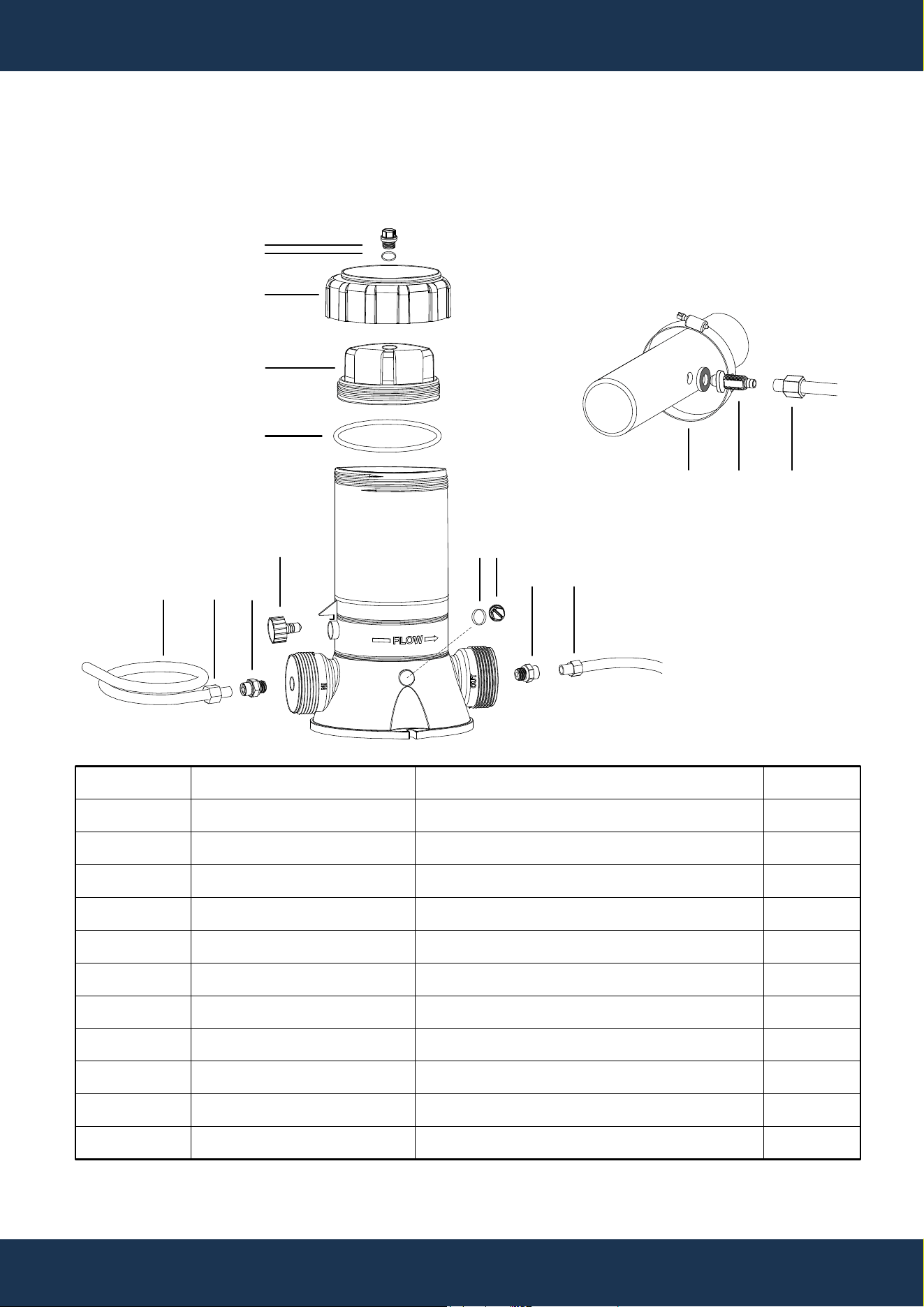
REPLACEMENT PARTS
PARTS DIAGRAM
ITEM
1
2
3
4
5
6
7
8
9
10
11
PART NUMBER
647016803080
647016802000
65431036080
88601004
647016875000
647016807080
647016806001
65749011080
647016805080
65021013000
647016873000
DESCRIPTION
COVER CAP
COVER
O-RING
DRAIN PLUG W/GASKET
CONTROL VALVE ASSEMBLY
INLET FITTING ADAPTER
COMPRESSION NUTS
PLASTIC TUBING - 8 FT.
SADDLE FITTING
SADDLE CLAMP
CHECK VALVE ASSEMBLY
QTY
1
1
1
2
1
2
4
1
2
2
1
1
2
3
2
5
678
4
711
7910
4

10
DISCLAIMER
DISCLAIMER
PLEASE READ THE FOLLOWING CAREFULLY
The manufacturer and/or distributor have provided the parts list and assembly diagram in this
manual for reference purposes only. They do not make any representation or warranty to the buyer
that they are qualified to make repairs to the product or replace any parts of the product. In fact, the
manufacturer and/or distributor expressly state that all repairs and parts replacements should be
undertaken by certified and licensed technicians, and not by the buyer.
The buyer assumes all risk and liability arising from their repairs to the original product or
replacement parts or arising from their installation of replacement parts. It is strongly advised that
qualified professionals handle any repairs or replacements to ensure safety and proper functioning
of the product. Improper installation and operation may result in injury, property damage, or voiding
of warranty. The manufacturer and/or distributor shall not be held responsible for any accidents,
damages, or malfunctions resulting from the buyer's installation and operation of the product. It is
essential to follow all safety guidelines and recommendations provided in this manual and to seek
professional assistance if unsure about the installation or operation procedures.
CUSTOMER SERVICE
If you have any questions about ordering our pool pumps and replacement parts or pool products,
please feel free to contact us using the following contact information:
Customer Service and Technical Support
Phone: (909) 628-0880
Email: [email protected]
Hours of Operation: Monday – Friday, 9AM – 4PM (CST)