Read all safety warnings and instructions. Failure to follow the warnings
and instructions may result in electric shock, fire and/or serious injury.
Save all warnings and instructions for future reference.
INSTALLATION AND USER’S GUIDE
ITEM: 75131
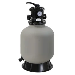
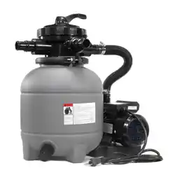
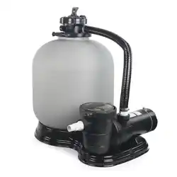
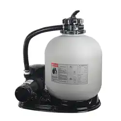
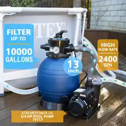
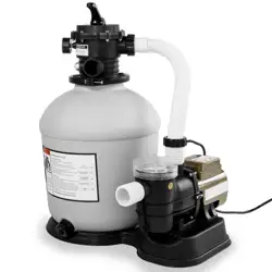
POOL PUMP AND SAND FILTER SYSTEM
0.75 HP 110 V 16 INCH 7-WAY ABOVE-GROUND
DANGER
75131

0
TABLE OF CONTENTS
31
WINTER (For Winterizing)
27
FILTER (Normal Operation)
26
RINSE (Initial Run)
25
BACKWASH (Initial Run)
25VALVE FUNCTIONS
24AFTER PRIMING THE PUMP
23PRIMING THE PUMP
22PRIOR TO START-UP
22OPERATION
PUMP AND SAND FILTER SYSTEM
11
INSTALLATION INSTRUCTIONS 12
ELECTRICAL
10PUMP LOCATION
10INSTALLATION
9SPECIFICATIONS
8PRODUCT DIMENSIONS
7
6PACKAGE CONTENTS
6OVERVIEW (PRODUCT INFORMATION)
4GENERAL SAFETY
2
Legends and Symbols
2IMPORTANT SAFETY INSTRUCTIONS
0TABLE OF CONTENTS
14
STEP 3: MEDIA ASSEMBLY INSTALLATION
13
STEP 2: SAND FILTER DRAIN INSTALLATION
12
STEP 1: PUMP BASE ASSEMBLY
17
STEP 6: FLANGE CLAMP INSTALLATION
16
STEP 5: PRESSURE GAUGE INSTALLATION
15
STEP 4: ADDING FILTER MEDIA
20
STEP 9: HOSE ATTACHMENT
19
STEP 8: HOSE ACCESSORIES ATTACHMENT
18
STEP 7: TANK ATTACHMENT
21
STEP 10: POWER CONNECTION
30
CLOSED (Shut Off The Flow To The Filter and Pool)
29
WASTE (Bypass Filter Media For Direct Water Exit)
28
RECIRCULATE (Move The Water Around Without Filtering)
35TROUBLESHOOTING
33
TIMER AND OPERATION MODES
33
TIMER SETUP
33CONTROL PANEL
34
REGULAR INSPECTION AND MAINTENANCE

43DISCLAIMER
42Parts Diagram
42REPLACEMENT PARTS
TABLE OF CONTENTS
1
43Customer Service
43Disclaimer
41Water Chemistry
40Pump Maintenance
40MAINTENANCE
IMPORTANT SAFETY INSTRUCTIONS
2
For safety reasons, children should not be allowed to use this product.
Failure to comply with all instructions and warnings may lead to severe bodily injury or
even death. It is strongly recommended that only a qualified pool service professional install and service
this product. Prior to using this product, installers, operators, and owners must carefully review these
warnings and all instructions provided in the owner's manual. It is essential to leave these warnings and
the owner's manual with the pool owner for their reference and safety.
ATTENTION INSTALLER: This manual contains vital information regarding the installation, operation,
and safe use of this product. It is essential to provide this manual to the end user of the product. Failure
to read and follow all instructions could lead to severe injuries.
USE OF NON-XTREMEPOWERUS REPLACEMENT PARTS VOIDS WARRANTY
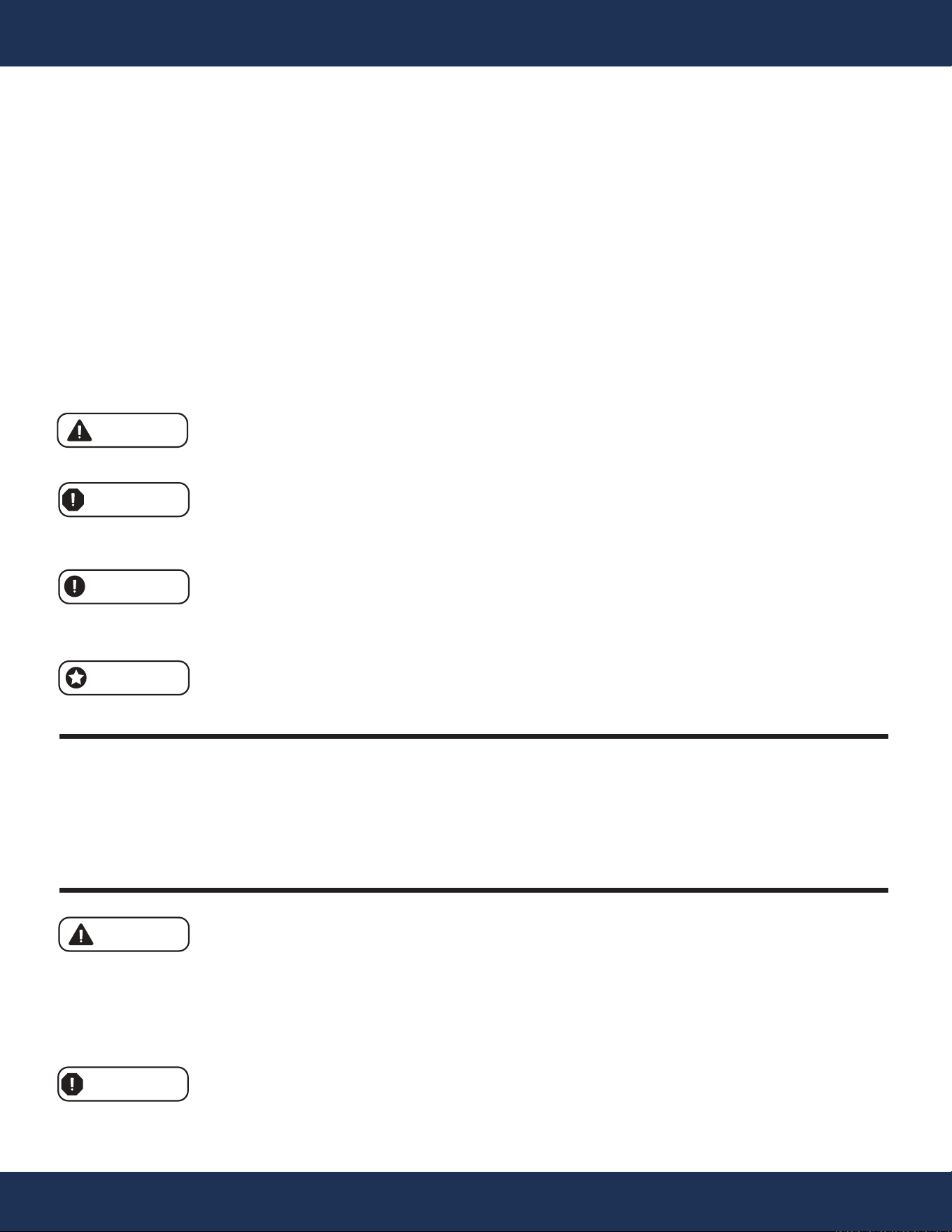
DANGER: Ignoring these hazards can result in death, severe personal injury, or
significant property damage.
WARNING: Indicates potential hazards that can result in severe personal injury,
death, or significant property damage. Ignoring these warnings presents a real
danger.
CAUTION: Indicates potential hazards that can result in minor or moderate personal
injury, property damage, or actions that are unpredictable and unsafe. Ignoring these
cautions presents a potential hazard.
NOTICE: This label indicates important special instructions that are not directly
related to hazards.
This guide provides instructions for installing and using the product. If you have any questions about the
product, please contact XtremepowerUS.
This guide contains important information about safely installing and operating this product. After
installation, make sure to share this information with the owner/operator or leave it with them for their
reference.
Legends and Symbols
When you come across the safety-alert symbol on the product or in this manual, pay attention to the
following signal words and remain vigilant about the potential for personal injury.
IMPORTANT SAFETY INSTRUCTIONS
DANGER
WARNING
WARNING
CAUTION
NOTE
DANGER

IMPORTANT SAFETY INSTRUCTIONS
3
This product is specifically designed for use with permanent swimming pools and, if
appropriately marked, can also be used with hot tubs and spas. However, it should not be used with
storable pools. A permanently installed pool is one that is built in or on the ground, or within a building,
making it incapable of being easily disassembled for storage. On the other hand, a storable pool is
designed to be disassembled and reassembled for storage while maintaining its original integrity. Please
ensure that this product is only used with permanent swimming pools and hot tubs or spas if appropriately
indicated. Avoid using it with storable pools to prevent potential hazards and ensure optimal performance.
Please note that this unit must only be connected to a supply circuit protected by a
ground-fault circuit-interrupter (GFCI). The installation of a GFCI is the responsibility of the installer, and
it should be regularly tested for proper functioning. To test the GFCI breaker, simply press the test button,
which should interrupt power. Pressing the reset button should restore power. If the GFCI fails to operate
as described, it is defective and should be replaced. If the GFCI interrupts power to the pump without
pressing the test button, it indicates the presence of a ground current and the possibility of electric shock.
In such cases, do not use the pump. Disconnect it immediately and seek the expertise of a qualified
service representative to address and rectify the issue before resuming use (to test the GFCI breaker).
Risk of electrical shock. Connect this product solely to a branch circuit that is
safeguarded by a ground-fault circuit interrupter (GFCI). If you are unable to confirm the presence of a
GFCI protection on the circuit, please seek assistance from a qualified electrician.
DANGER
WARNING
WARNING
IMPORTANT SAFETY INSTRUCTIONS
4
• During installation, ensure proper drainage around the pump to prevent water from entering the
electrical components.
• To ensure optimal performance, it is crucial to use the proper size pump for the specific application
and install it correctly. Only through meticulous sizing and installation can the pump function as
intended.
• The use of pumps that are improperly sized, installed, or employed for applications other than their
intended purpose can lead to severe personal injury or even death. These risks encompass
potential hazards such as electric shock, fire, flooding, suction entrapment, or critical injuries and
property damage resulting from structural failures of the pump or other system components. It is
essential to strictly adhere to the correct sizing, installation, and designated usage to mitigate
these potential dangers and ensure the safety of all users and the surrounding environment.
• The pump and sand filter system is not designed to be submersible.
• Do not attempt to open the inside of the drive or motor enclosure, as there is a capacitor bank
that can retain a potentially dangerous electrical charge, even when the unit is not powered.
• Disconnect the main power plug to turn off the pump before performing any maintenance on the
pump and sand filter system.
• Before working on the filter, disconnect the power plug to the pump and release the air pressure
to the filter tank.
• The sand filter is designed to operate with water temperatures between +32.0°F to +113.0°F
(+0°C to +45°C). Operating the filter outside of this temperature range may cause damage.
• Chemical spills can damage pools/spas and malfunction equipment, risking injury or property
harm. Avoid storing chemicals near equipment.
• This appliance is not intended for use by individuals (including children) with reduced physical,
sensory, or mental capabilities, or those lacking experience and knowledge, unless they have
received supervision or instruction regarding its safe usage from a responsible person.
GENERAL SAFETY
WARNING
WARNING
DANGER
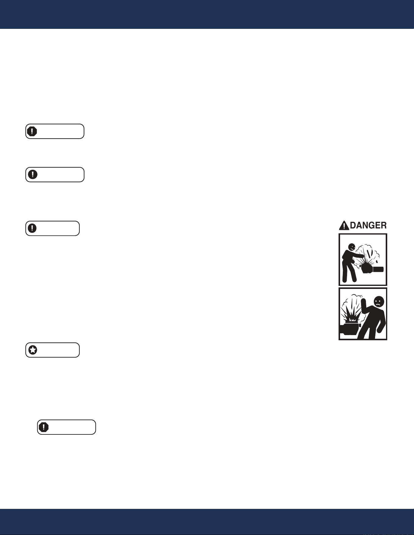
The pump has the potential to generate significant levels of suction within the plumbing system's
suction side. This heightened suction presents a considerable risk if individuals come too close to the
suction openings. Being near these openings can result in severe injuries caused by the intense
vacuum or may lead to entrapment and drowning.
5
IMPORTANT SAFETY INSTRUCTIONS
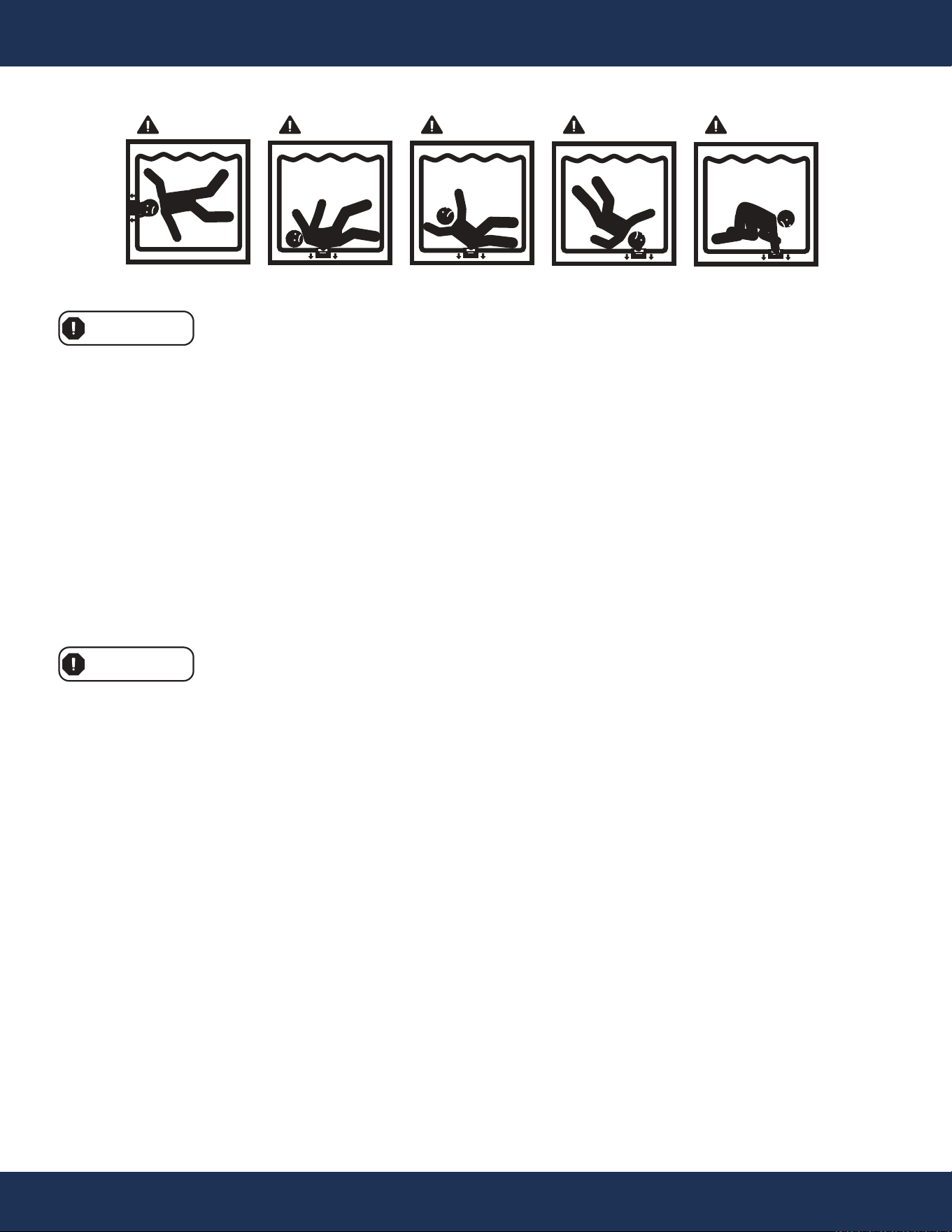
SUCTION ENTRAPMENT HAZARD
DANGER DANGER
DANGER DANGER DANGER
WARNING
WARNING
To minimize the risk of injury caused by suction entrapment hazards, please follow these safety
guidelines:
• Use only properly installed and secured ANSI/ASME A112.19.8 approved anti-entrapment suction
covers for each drain.
• Ensure that each suction cover is installed at least three (3') feet apart, measured from the nearest
point to nearest point.
• Regularly check all suction covers for cracks, damage, and excessive weathering.
• Promptly replace any loose, cracked, damaged, broken, or missing cover with an appropriate
certified one.
• Periodically replace drain covers as necessary since they deteriorate over time due to exposure to
sunlight and weather.
• Avoid placing hair, limbs, or your body near any suction cover, pool drain, or outlet.
By adhering to these precautionary measures, you can significantly reduce the risk of injury
associated with suction entrapment hazards.
6
OVERVIEW (PRODUCT INFORMATION)
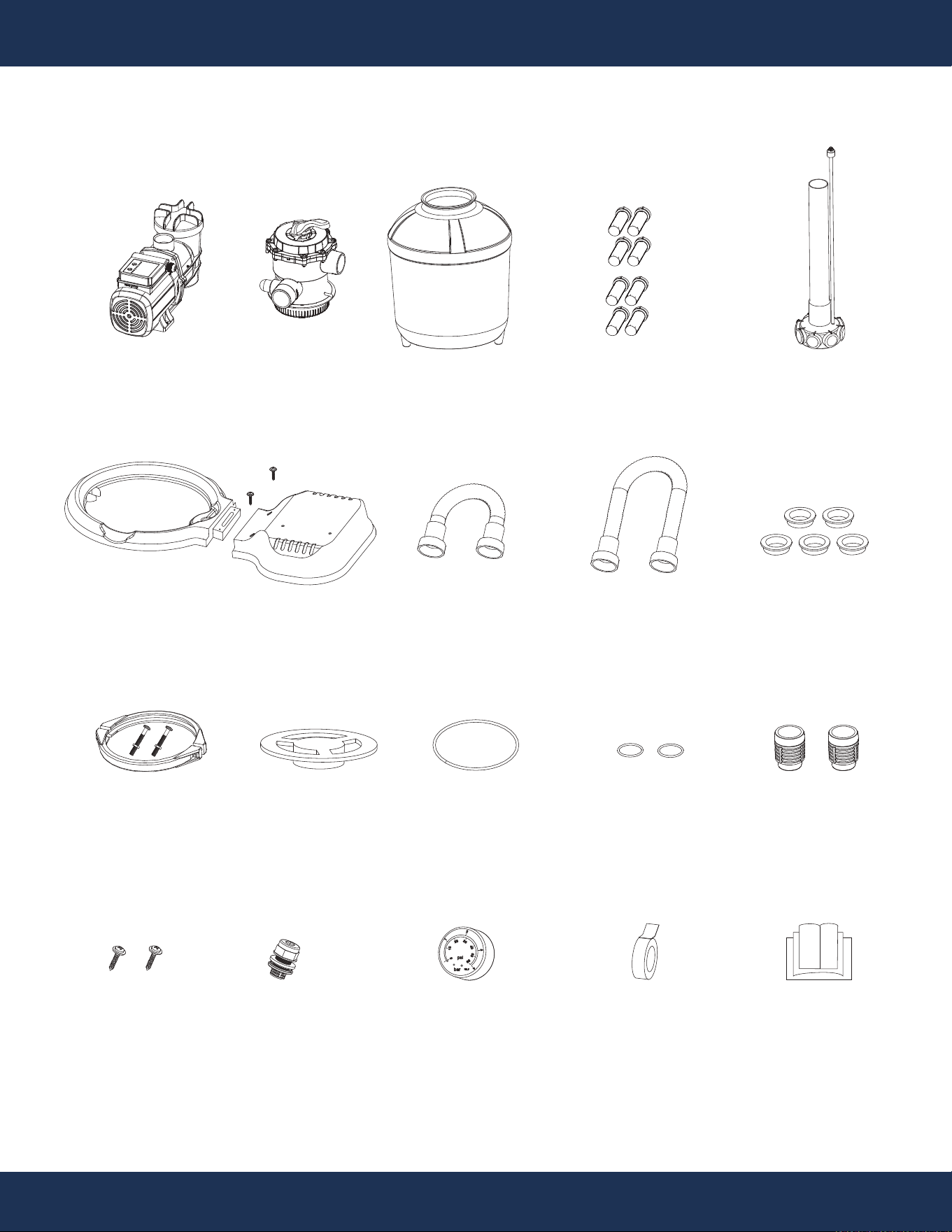
PACKAGE CONTENTS
OVERVIEW (PRODUCT INFORMATION)
PARTS # 6
PUMP WITH STRAINER
1 PC(S)
PARTS #
1
7-WAY VALVE
1 PC(S)
PARTS #
13
FILTER TANK
1 PC(S)
PARTS #
16
FLANGE CLAMP
1 SET(S)
PARTS #
8
SUPPORT BASE
1 SET(S)
PARTS #
2
SHORT HOSE
1 SET(S)
PARTS #
9
DRAIN PLUG
1 SET(S)
PARTS #
4
CONNECTOR
2 PC(S)
psi
bar
KL1.6
1
0
10
20
30
40
50
60
2
3
4
PARTS # 15
LARGE O-RING
1 PC(S)
PARTS #
18
PRESSURE GAUGE
1 PC(S)
PARTS #
11 & 14
MEDIA ASSEMBLY
W/ AIR RELEASE
1 SET(S)
PARTS
USER’S GUIDE
1 PC(S)
PARTS # 17
FUNNEL
1 PC(S)
PARTS # 5
SMALL O-RING
2 PC(S)
PARTS
TEFLON TAPE
1 PC(S)
PARTS # 3
GASGET
5 PC(S)
PARTS # 7
SCREW
2 PC(S)
PARTS # 12
LONG HOSE
2 SET(S)
1.5 FT 5.4 FT
PARTS # 10
MEDIA ASSEMBLY
LATERAL
8 PC(S)
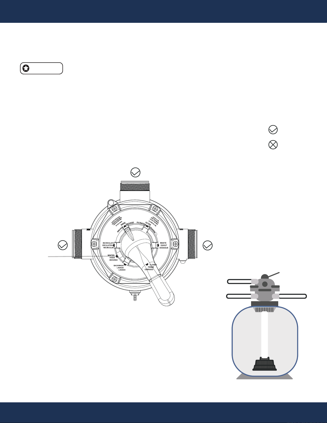
7
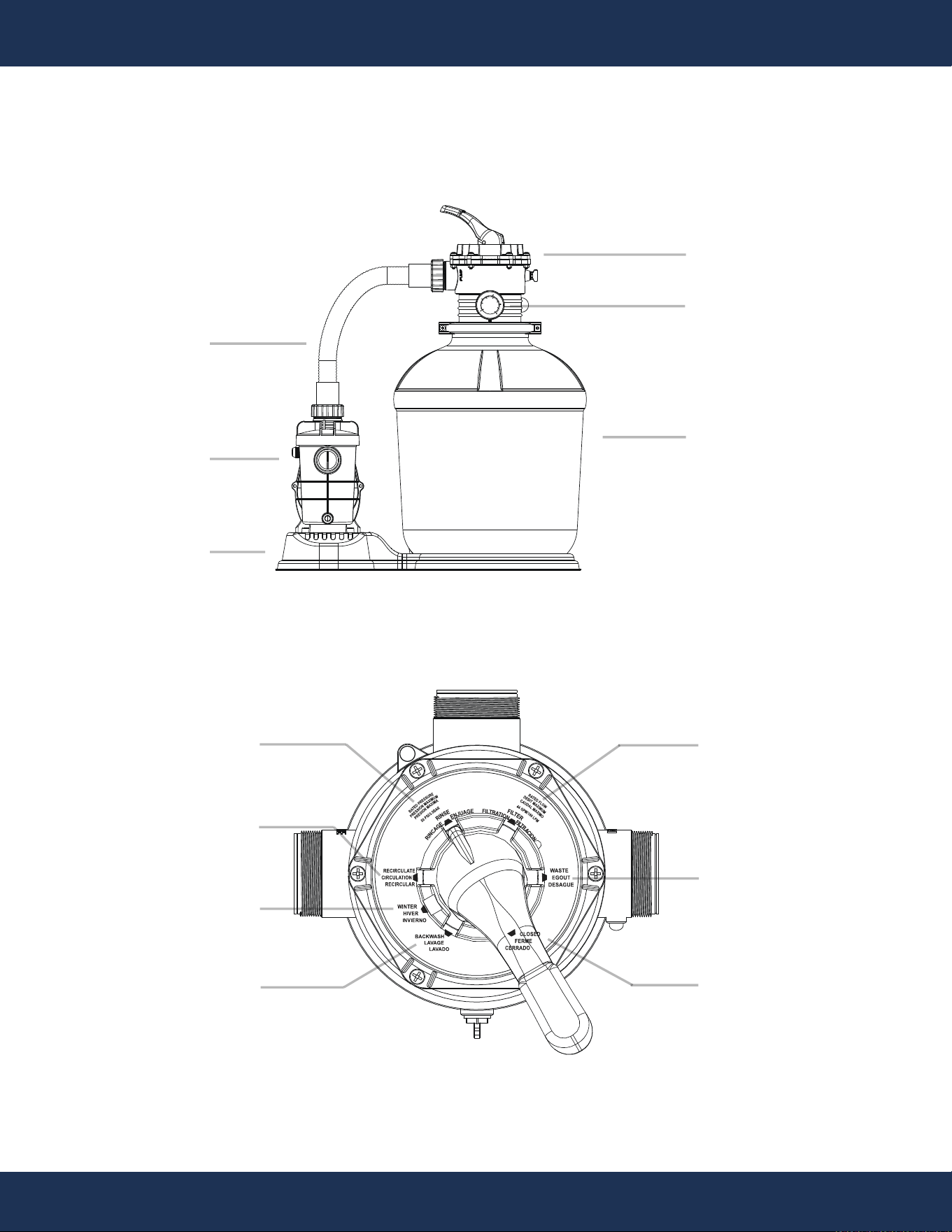
OVERVIEW (PRODUCT INFORMATION)
PUMP
PIPE
PUMP BASE
7-WAY VALVE
PRESSURE GAGE
FILTER TANK
PUMP AND SAND FILTER SYSTEM
psi
bar
KL1.6
1
0
10
20
30
50
60
2
3
4
40
0
RECIRCULATE
RINSE
WINTER
BACKWASH
FILTER
WASTE
CLOSED
8
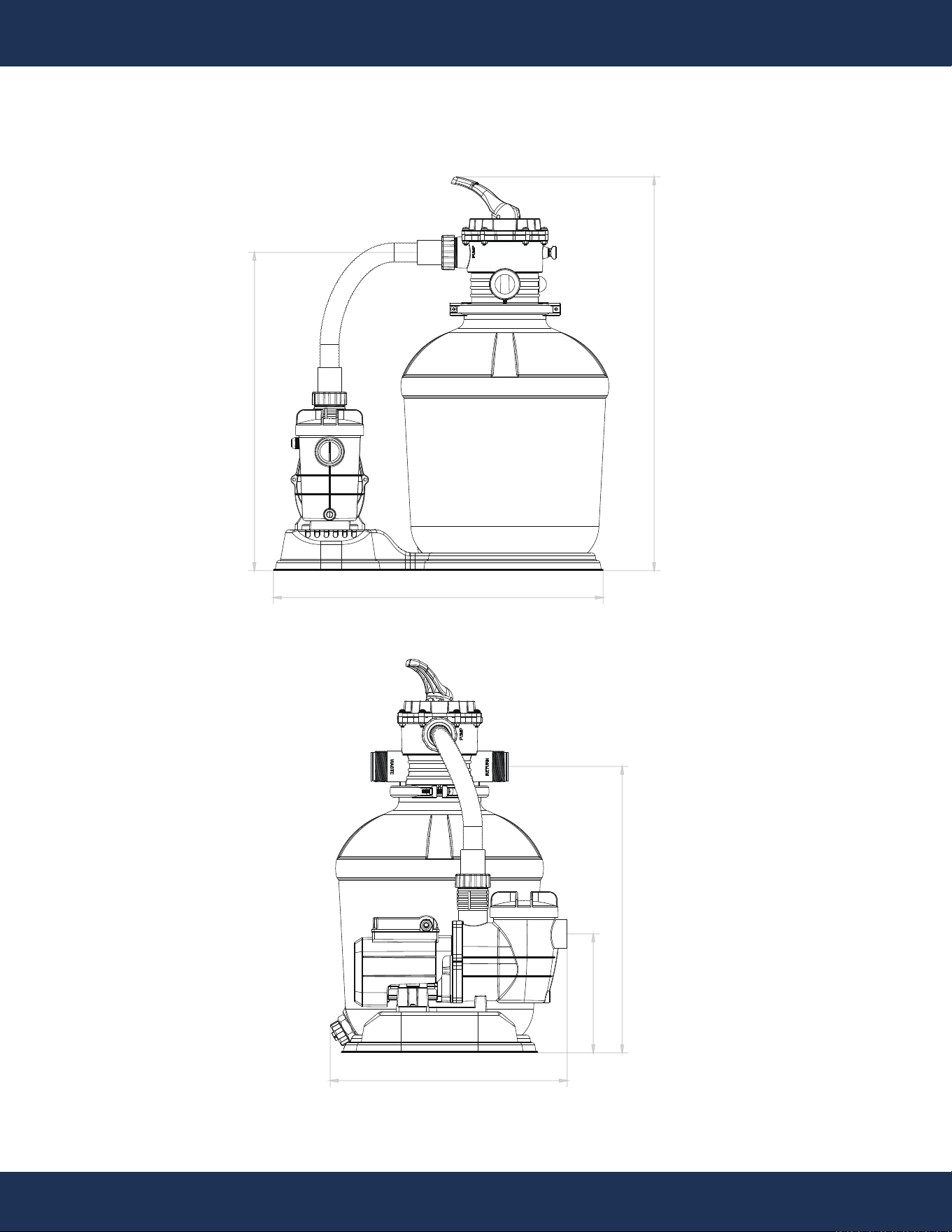
PRODUCT DIMENSIONS
OVERVIEW (PRODUCT INFORMATION)
25.4”
24.4” 30.2”
22”
9.1”
18.2”

9
OVERVIEW (PRODUCT INFORMATION)
SPECIFICATIONS
INPUT VOLTAGE
FREQUENCY
SPEED
RPM
HORSEPOWER
WIRE
MAXIMUM CONTINUOUS LOAD
AMBIENT CONDITIONS
STORAGE
OPERATING HUMIDITY
POOL TYPE
HMAX (MAXIMUM HEAD)
QMAX (MAXIMUM FLOWRATE)
WEF (WEIGHTED ENERGY FACTOR)
CERTIFICATION
FEATURE
110 V
60 HZ
SINGLE SPEED
3450 RPM
0.75 HP
PLUG
530 W
-40°F TO 140°F (-40°C TO 60°C)
32°F TO 122°F (0°C TO 50°C)
RELATIVE 0 TO 95 % NON-CONDENSING
ABOVE-GROUND
36 FT
41.5 GPM
4.6
ETL
DOE
CEC
THERMAL PROTECTED
HEAVY-DUTY LONG-LASTING CASE
10
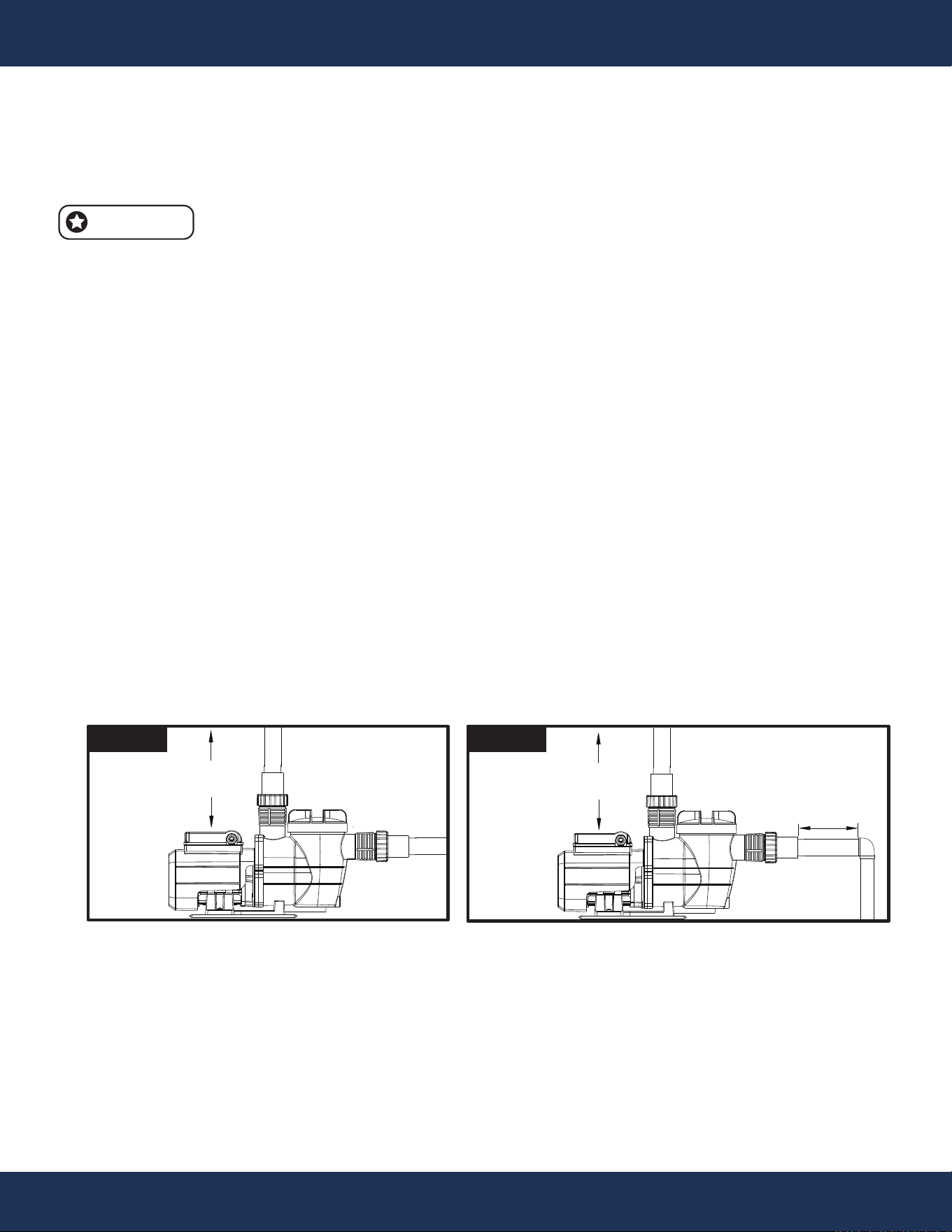
INSTALLATION
Figure 2
5 × SUCTION PIPE
DIAMETER
6” (15.2cm)
MINIMUM
Figure 1
6” (15.2cm)
MINIMUM
PUMP LOCATION
While the pump is designed for outdoor use, it is advisable to position both the pump and filter in the
shade to shield them from continuous direct heat. Select a well-drained location that will not flood
during rainy periods. Never install the pump and filter in a damp or poorly ventilated area. Keeping
the motor clean is crucial, as pump motors require unrestricted air circulation to aid in cooling.
• This pump should not be installed within an outer enclosure or beneath the skirt of a hot tub or
spa, unless there are specific markings indicating its suitability for such installation.
• It is essential to mechanically secure the pump and sand filter system to the pump base during
installation. Proper mechanical securing ensures stability and safe operation of the pump during
its use.
Ensure that the pump location satisfies the following requirements:
• Position the pump as close to the pool or spa as feasible. Ensuring it is placed on a dry, well-
ventilated surface away from direct sunlight. Consider the following factors:
◦ Ensure proper drainage away from the pump.
◦ Provide adequate ventilation for the pump motor.
◦ Allow easy access for future servicing and winterizing needs.
◦ Protect the pump from exposure to the elements.
• Ensure a minimum distance of 5 feet from the inside wall of the pool and spa during installation.
• Keep a minimum distance of 3 feet between the pump and the heater outlet.
• Avoid installing the pump at a location higher than 10 feet above the water level.
• Choose a well-ventilated site for the pump, offering protection from excess moisture, such as rain
gutter downspouts or sprinklers.
• Allow a rear clearance of at least 3 inches during installation to enable easy motor removal for
maintenance and repair. Refer to Figure 1 and Figure 2 for further details.
NOTE
14
INSTALLATION
10
INSTALLATION
INSTALLATION

11
INSTALLATION
ELECTRICAL
RISK OF ELECTRICAL SHOCK OR ELECTROCUTION.
It's crucial to follow the National Electrical Code and all relevant local codes and
ordinances. Going against these rules can result in a high risk of electrical shock,
potentially leading to severe injury, death, or property damage for individuals
involved. To prioritize safety and prevent potential hazards, adhering to electrical
safety regulations and guidelines is crucial.
Always ensure the power to the pump is disconnected from the power source before performing
any service or maintenance. Failure to do so can lead to severe injury or even death for service
personnel, pool users, or others due to electric shock, and may also result in property damage. Prior
to servicing the pump, ensure complete disconnection from the power source to ensure the safety of
everyone involved and to prevent any potential hazards or accidents.
Prior to commencing any work on the pump, thoroughly read and familiarize yourself with all
servicing instructions. This practice ensures your understanding of the proper procedures and
precautions necessary for safe and effective pump servicing. Neglecting to do so may result in
accidents, injuries, or damage to the pump or surrounding equipment. Prioritize safety by carefully
reviewing all instructions before undertaking any maintenance tasks.
DANGER
12
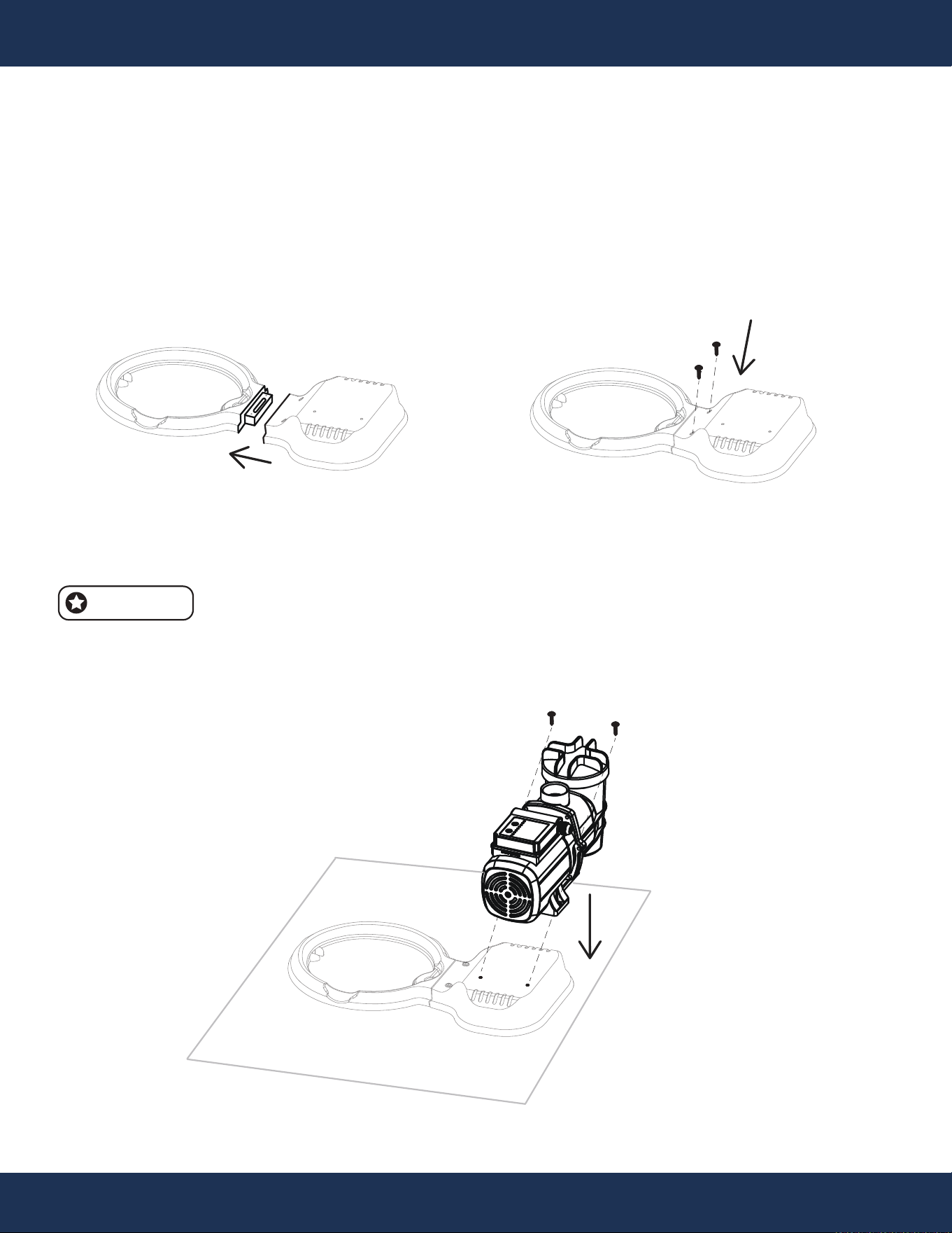
INSTALLATION
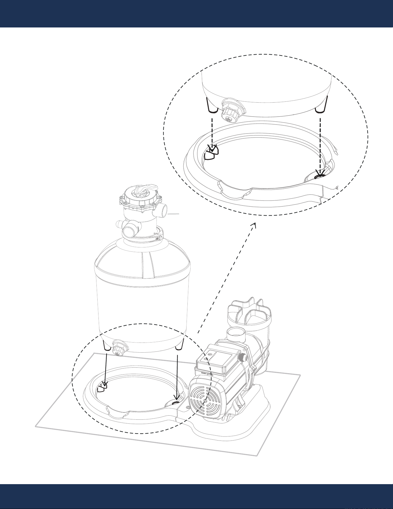
STEP 1: PUMP BASE ASSEMBLY
Figure A
The equipment must be placed on a level surface with adequate ground hardness; if
positioned on grass, a flat wooden board should be used as a base for leveling.
NOTE
Figure B
INSTALLATION INSTRUCTIONS
For detailed guidance on safe installation, please refer to the IMPORTANT SAFETY INSTRUC-
TIONS. These instructions are vital to ensure the pump is set up correctly, maintaining safety and
optimal performance.
PARTS # 8 PARTS # 8
PARTS # 6
PARTS # 7
13
INSTALLATION
9.1 9.2 9.3 9.4
9.49.3
9.4
9.3
9.1
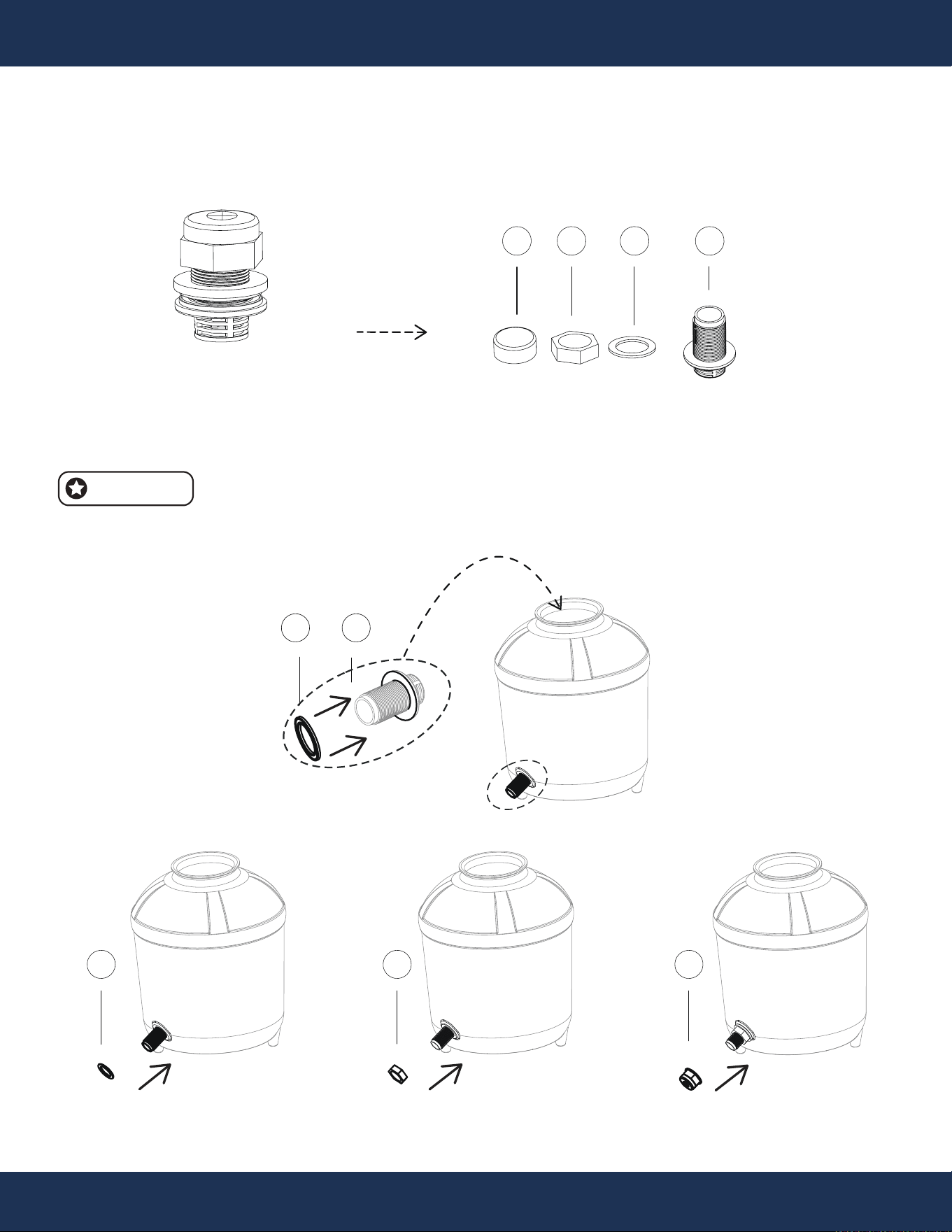
STEP 2: SAND FILTER DRAIN INSTALLATION
Figure D
Figure C
PARTS # 9
PARTS # 13
Do not overtighten the components of Part #9.
NOTE
14
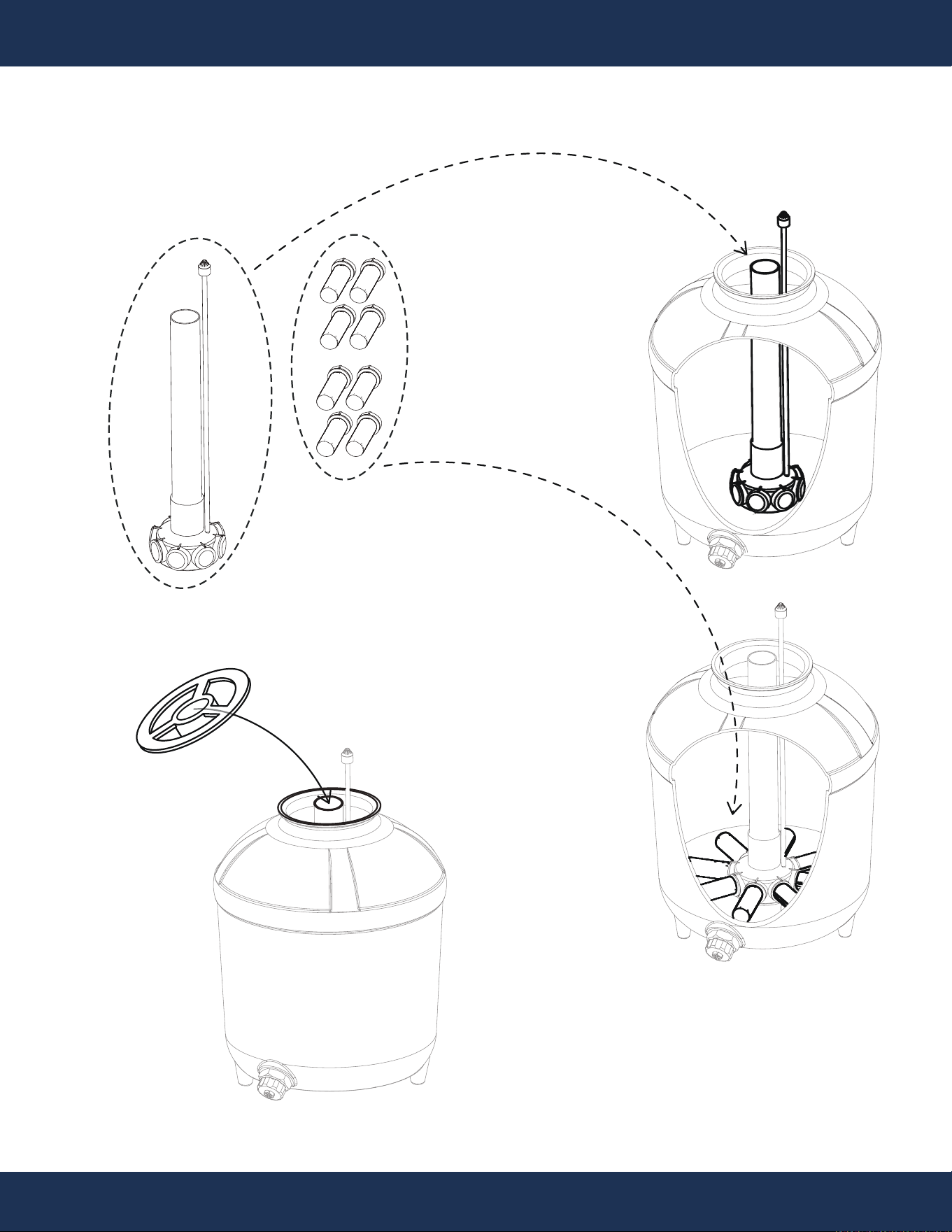
INSTALLATION
STEP 3: MEDIA ASSEMBLY INSTALLATION
Figure E
PARTS # 11 & 14
PARTS # 13
Figure F
PARTS # 17
REMOVE IT BEFORE
INSTALL VALVE
PARTS # 10
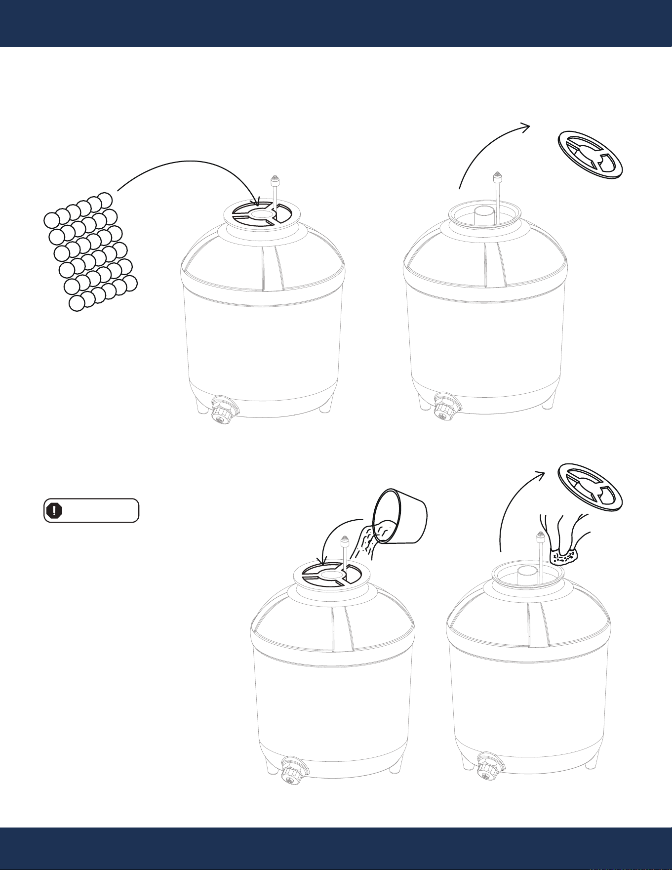
15
INSTALLATION
15
INSTALLATION
Figure G (filter balls not included)
Figure H (filter sand not included)
Use only POOL FILTER SAND for this step.
WARNING
Sand Selection and Loading Requirements:
Commonly used sand: #20 (0.71MM quartz sand)
Sand density: 0.1 LB / FT³ (1.6 KG / M³)
Standard weight for sand loading: 110 LBS
Maximum sand loading in the tank: Fill up to
two-thirds of the filer tank.
STEP 4: ADDING FILTER MEDIA
Pool Filter Media Sand
Pool Filter Media Balls
PARTS # 17
REMOVE IT BEFORE
INSTALL VALVE
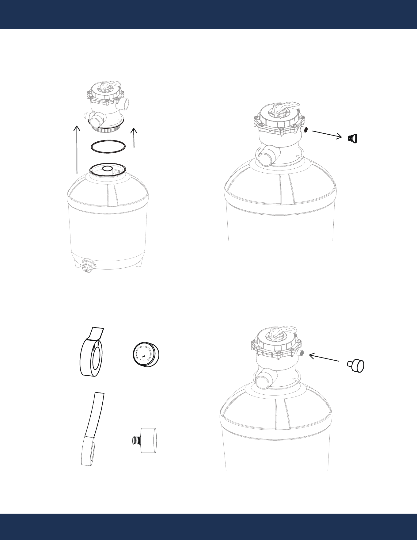
16
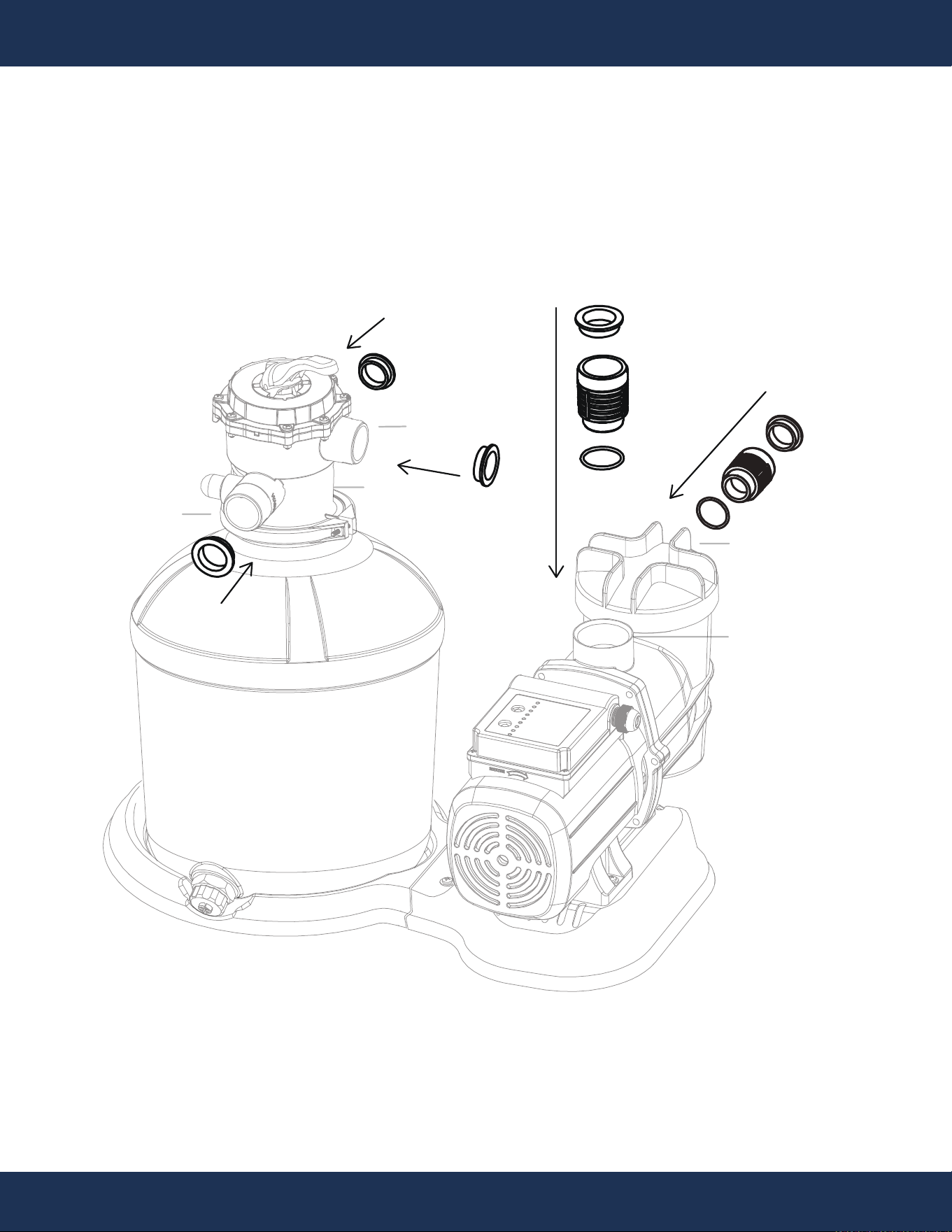
INSTALLATION
STEP 5: PRESSURE GAUGE INSTALLATION
Figure I
Figure J
Figure K Figure L
psi
bar
KL1.6
1
0
10
20
30
40
50
60
2
3
4
PRESSURE GAUGE
PORT PLUG
TEFLON TAPE
TEFLON TAPE
PRESSURE GAUGE PORT
PRESSURE GAUGE PORT
PARTS #
1
PARTS # 13
PARTS # 15
PARTS # 18
PARTS # 18
PARTS # 18
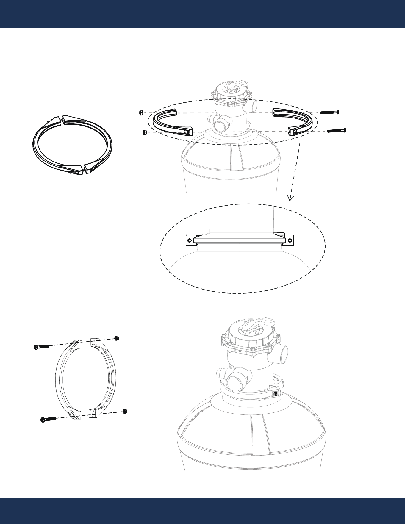
17
INSTALLATION
STEP 6: FLANGE CLAMP INSTALLATION
Figure M
PARTS # 16
PARTS # 16
STEP 7: TANK ATTACHMENT
18
INSTALLATION
Figure N
PUMP INLET
PARTS # 8
PARTS # 13
PARTS # 8
PARTS # 13
19
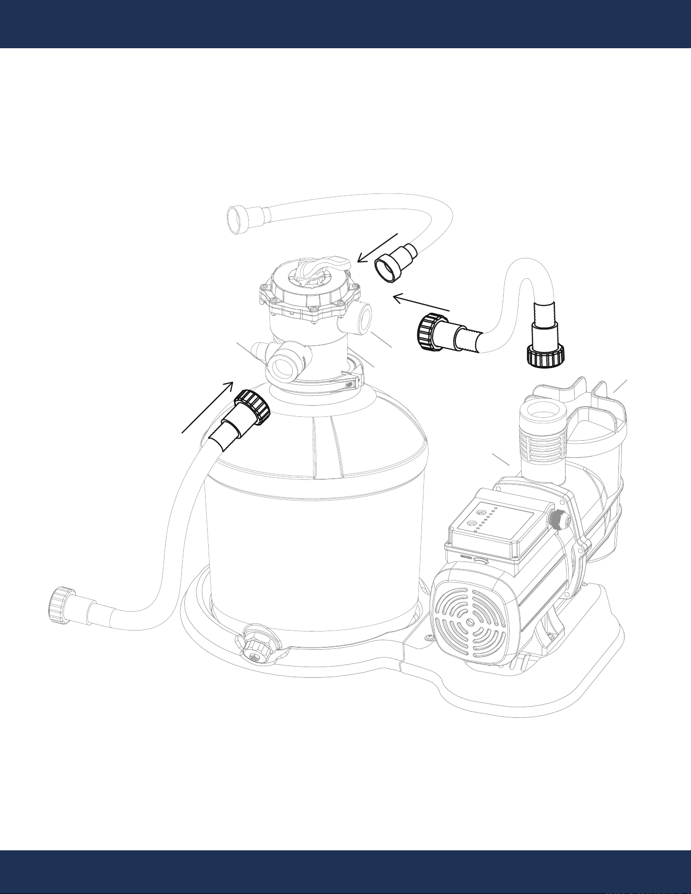
INSTALLATION
STEP 8: HOSE ACCESSORIES ATTACHMENT
Figure O
PUMP OUTLET
POOL OUTLET
PUMP INLET
WASTE OUTLET
POOL INLET
PARTS # 3
PARTS # 3
PARTS # 4
PARTS # 5
PARTS # 3
PARTS # 3
PARTS # 3
PARTS # 4
PARTS # 5
20
INSTALLATION
STEP 9: HOSE ATTACHMENT
Figure P
PUMP OUTLET
POOL OUTLET
PUMP INLET
WASTE OUTLET
POOL INLET
PARTS # 12
PARTS # 12
PARTS # 2
21
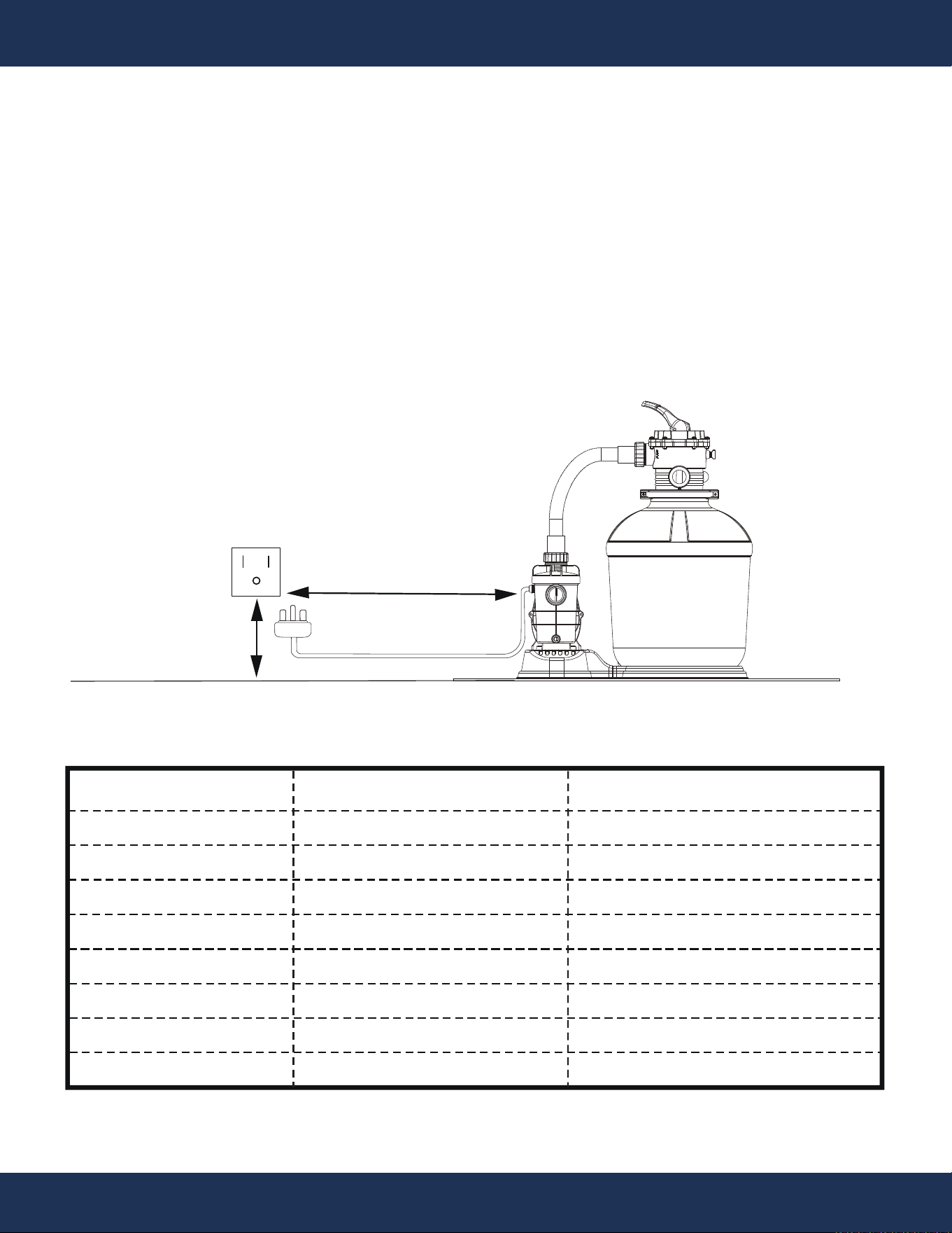
INSTALLATION
STEP 10: POWER CONNECTION
A. Refer to the details below for the minimum distance in inches between the ground fault
protection socket and the pump and sand filter system. (Figure R)
B. Use an 18 AWG extension cord capable of handling the electrical load of the filter pump.
Figure Q
4
4
4
5
5
5
6
6
0.5
1.0
1.5
2.0
2.5
4.0
5.0
6.0
Pool Capacity (Gallons) Duration of Each Run (Hours) Operating Frequency (Hours/Run)
300
600
900
1200
1500
2000
2500
3000
Pump Running Time Suggestion Chart
22
OPERATION
PRIOR TO START-UP
OPERATION
NOTE
WARNING
WARNING
CAUTION
If the circulation equipment must remain in the plumbing system during the water pressure test,
exercise caution and do not apply more than 10 PSI pressure to the system. Additionally, before
removing the pump strainer cover, be sure to release water pressure.
When starting the circulating pump system, ensure that all suction and discharge valves are OPEN,
along with the filter air relief valve (if available) on the filter. This critical step is essential for proper
pump operation and to prevent potential severe personal injuries.
Operate with caution: This pump and sand filter system operates simply by plugging in to turn on,
and power starts immediately. To turn it off, simply unplug, and power is cut off immediately.
This pump and sand filter system is designed to work seamlessly with a Swimming Pool Outdoor
Programmable Timer outlet, enhancing control and efficiency. Highly recommend using such a timer
for optimized performance.
If it is necessary to perform a water pressure test before the initial use to ensure the plumbing
system is functioning properly, the following criteria should be followed:
• Engage the services of a professional to perform the water pressure test. Their expertise will
ensure accurate and safe testing of the plumbing system.
• Before conducting the test, ensure all XtremepowerUS pump and system components are
removed from the plumbing system. This ensures that the test is performed independently of the
pump and its components.
23
OPERATION
CAUTION
NEVER OPERATE THE PUMP WITHOUT WATER. Water cools and lubricates the mechanical shaft
seal. Running the pump dry can damage the seals, causing leaks, flooding, and voiding the
warranty.
PRIMING THE PUMP
WARNING
Before operating the pump, ensure it has been properly primed as water is essential for cooling and
lubricating the seal.
• To begin, fill the strainer housing with water up to the level of the suction pipe. If any water
leakage is observed from the pump or filter, DO NOT start the pump. In such cases, it is essential
to address the leakage issue before proceeding.
• If no leakage occurs, you may proceed to start the pump. However, ensure that you stand at
least 10 feet away from the pump and/or filter after starting it.
DANGER
Avoid installing 90° elbows directly into the pump inlet or outlet. This will help maintain efficient pump operation.
Before removing the strainer cover, follow these steps:
• STOP the pump before proceeding.
• CLOSE the valves in the suction and outlet pipes.
• RELEASE ALL PRESSURE from the pump and piping system.
• After removing the strainer cover, fill the strainer housing with water.
• If necessary, clean and lubricate the strainer cover O-ring with silicone based
lubricant.
• Replace the strainer cover on the strainer housing.
• OPEN the suction and outlet pipe valves.
• Refill basket with water.
CAUTION
NOTE
WARNING
Priming Instructions:
• Confirm that all connections are secure.
• Clean the pool thoroughly before filling to avoid damage to the pump and filter from excessive dirt and large
particles.
◦ Ensure all suction and discharge valves are fully open before starting the system.
◦ Failure to do so could result in severe personal injury.
◦ Before starting the pump, make sure the filter vessel is filled with water.
◦ Starting the pump without water may cause damage to the pump.

24
OPERATION
Priming Instructions: (Continued)
• Open all pool suction and WASTE lines for free water flow to the WASTE line. Press down and turn the top
mount valve handle to the “BACKWASH” position.
• Inspect the valve clamp for proper tightness.
• Prime and activate the pump to fill the filter tank with water.
• Observe the WASTE line for a steady flow of water. Operate the pump for a minimum of 2 minutes or until
the backwash water runs clear, to eliminate impurities and fine sand particles from the media.
• Switch off the pump and adjust the valve to the "RINSE" position. Confirm that all pool suction and WASTE
lines are open for unrestricted water flow. Avoid running the sand filter dry. Maintain a safe distance from
the filter and start the pump.
• Continue running the pump for at least two minutes.
• Turn off the pump and switch the valve to the "Filtration" position. Check that all pool suction and RETURN
lines are open, ensuring free water circulation to and from the pool. Keep clear of the filter and initiate the
pump.
• The filter will begin its filtering cycle. Verify that water is circulating back into the pool and record the
operating pressure with a clean filter.
• Inspect the system for leaks. In case of a leak, turn off the pump before addressing it.
• Monitor the filter pressure as it cleans the pool water. When the pressure gauge shows a 5-10 PSI
(0.34-0.69 BAR, this value may change based on the pool's pump and piping) increase over the initial clean
filter reading, initiate the BACKWASH cycle for the filter.
AFTER PRIMING THE PUMP
• Once the pump is primed, turn it on and open all suction and discharge line valves.
• Allow time for the pump to expel air from the suction lines.
• If there's no water flow within five minutes, stop the pump and re-prime it.
• Check for air leaks and refer to the Troubleshooting section if the pump isn't working correctly.
Checking for Air Bubbles:
• After running the pump for about ten minutes, check the return fittings for air bubbles.
• Continuous air bubbles may indicate a leak in the suction line; fix leaks promptly to avoid further
problems.
Controlling Output:
• Keep the gate valve in the suction line fully open while the pump is running.
• To adjust the output, if necessary, use a valve on the return line.
WARNING
Never operate the pump with closed suction or discharge valves.
25
OPERATION
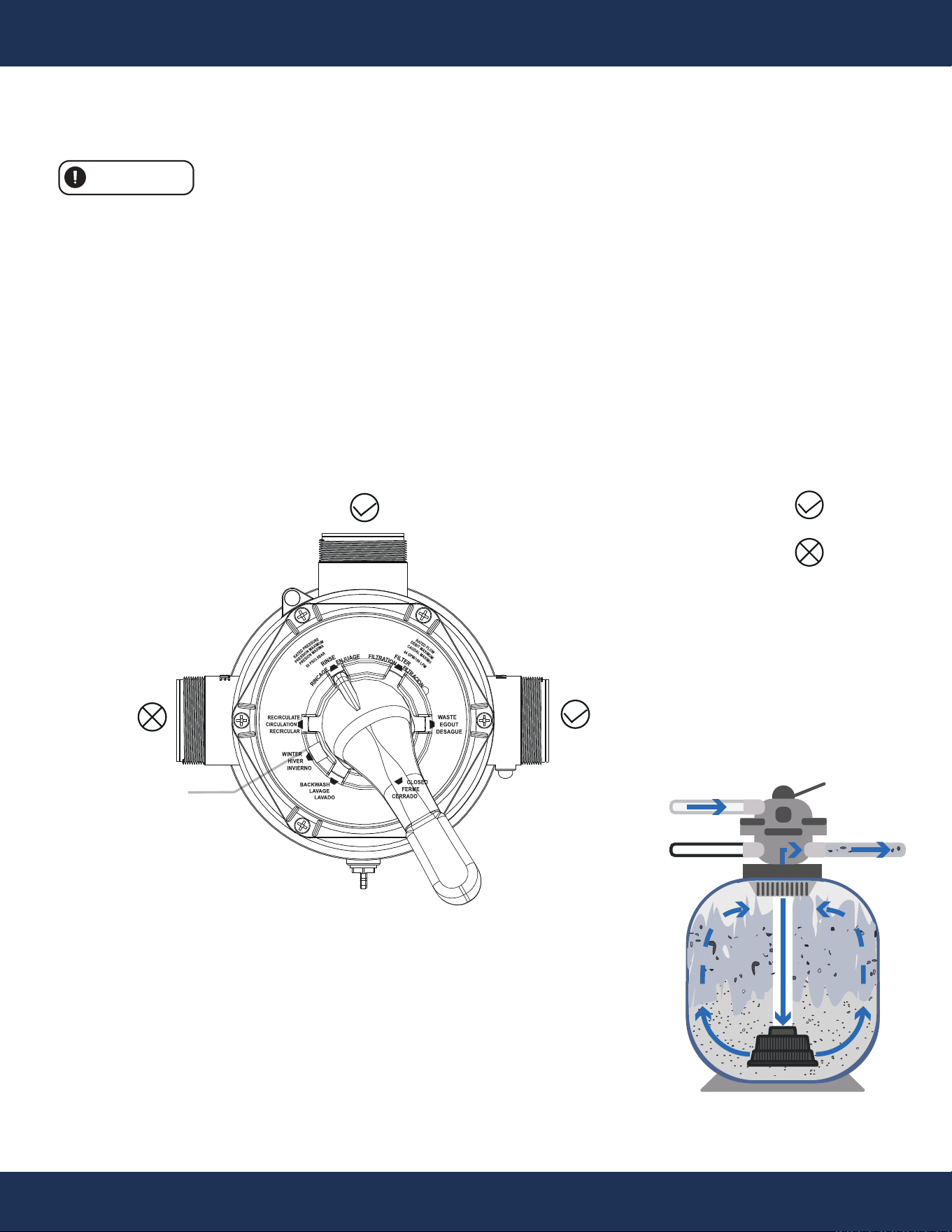
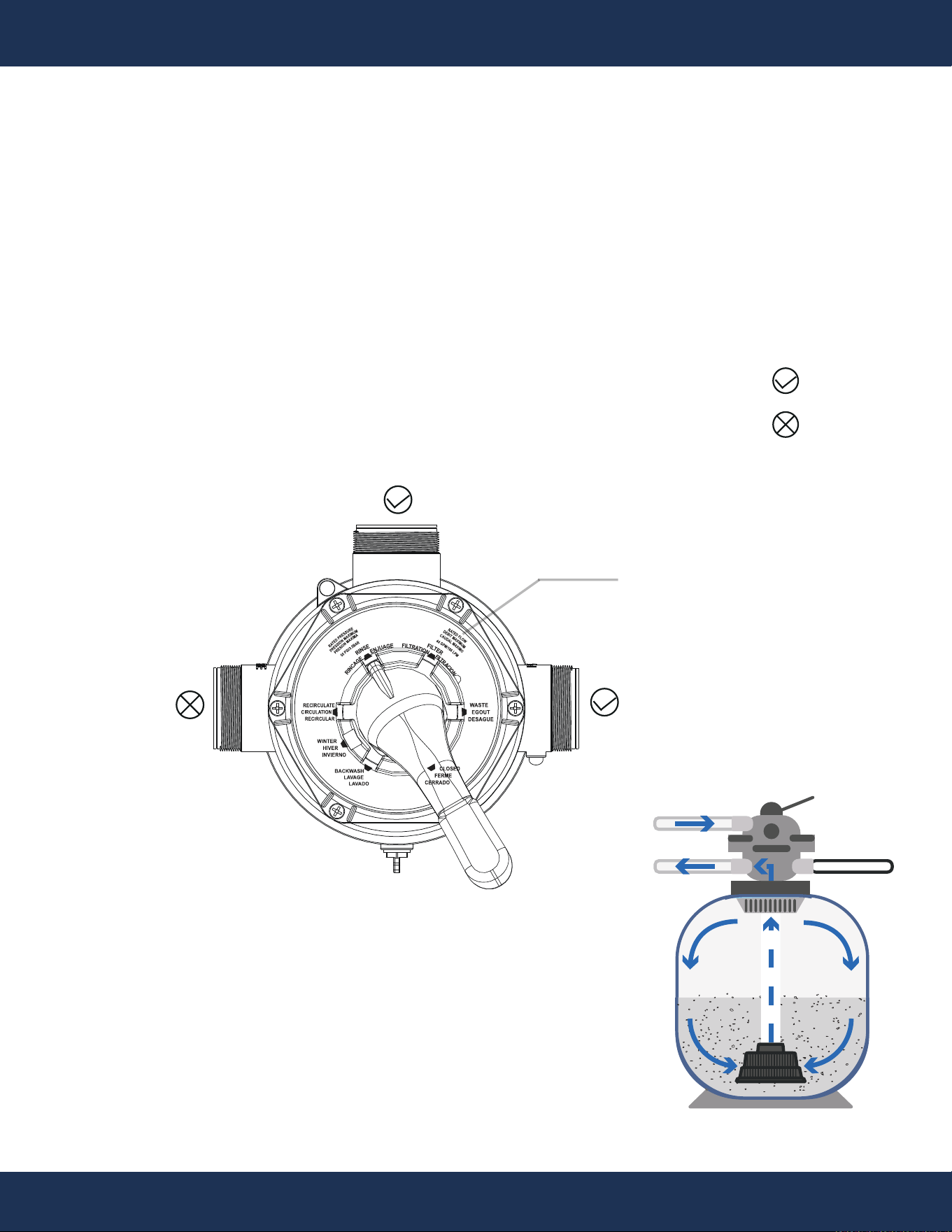
BACKWASH (Initial Run)
Use this setting to clean the filter. When the filter pressure gauge rises 5-10 PSI (0.0.34-0.69 BAR, this
reading may vary depending on the pool's pump and general piping system) above the start-up clean
pressure.
• Turn off the pump and set the valve to the "BACKWASH" position.
• Start the pump and backwash until the water in the sight glass is clear. This usually takes about 2
minutes or less, depending on the amount of dirt accumulated, and then turn off the pump.
Proceed to “RINSE”.
: Opened
: Closed
VALVE FUNCTIONS
CAUTION
Never operate the pump without water.
IN
OUT
WST
Pump Line
Return Line
Waste
Figure R
WASTE
BACKWASH
PUMP
RETURN
26
OPERATION
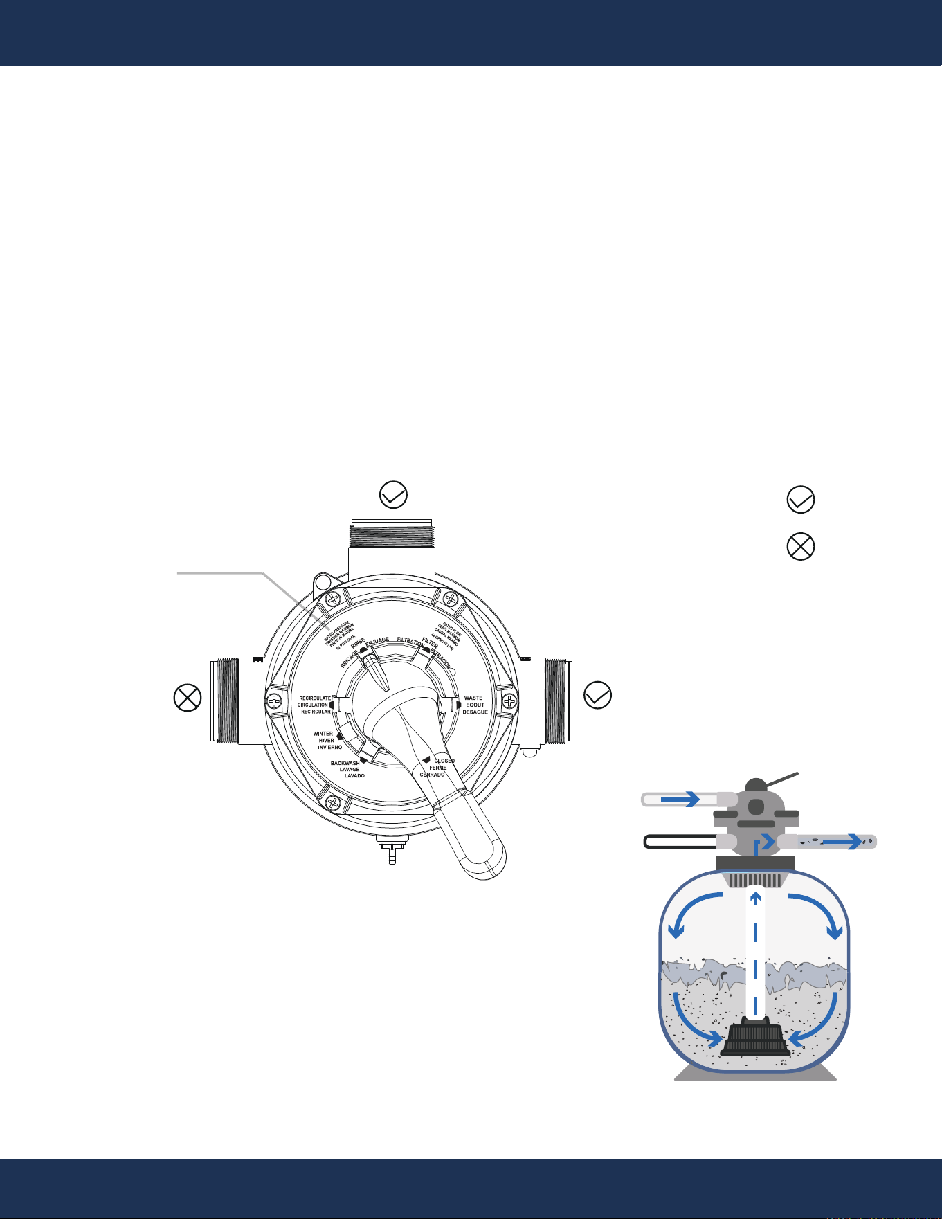
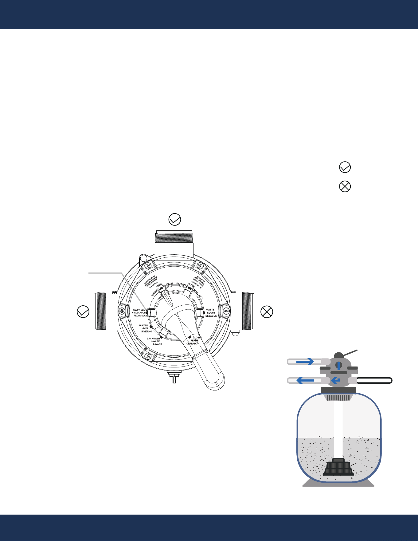
RINSE (Initial Run)
This ensures that all the dirty water from backwashing is rinsed out of the filter and goes to waste,
preventing possible return to the pool.
• After backwashing, keep the pump off and set the valve to "RINSE" position and start the pump for
about 0.5 to 1 minute.
• During rinsing, discharge water through the drain pipe. After sufficient rinsing, stop the pump, set
the valve to “Filtration”, and start the pump for normal filtering.
IN
OUT
WST
Pump Line
Waste
Figure S
Return Line
WASTE
RINSE
PUMP
RETURN
: Opened
: Closed
27
OPERATION
Pump Line
Return Line
Waste
IN
OUT
WST
WASTE
FILTER
PUMP
RETURN
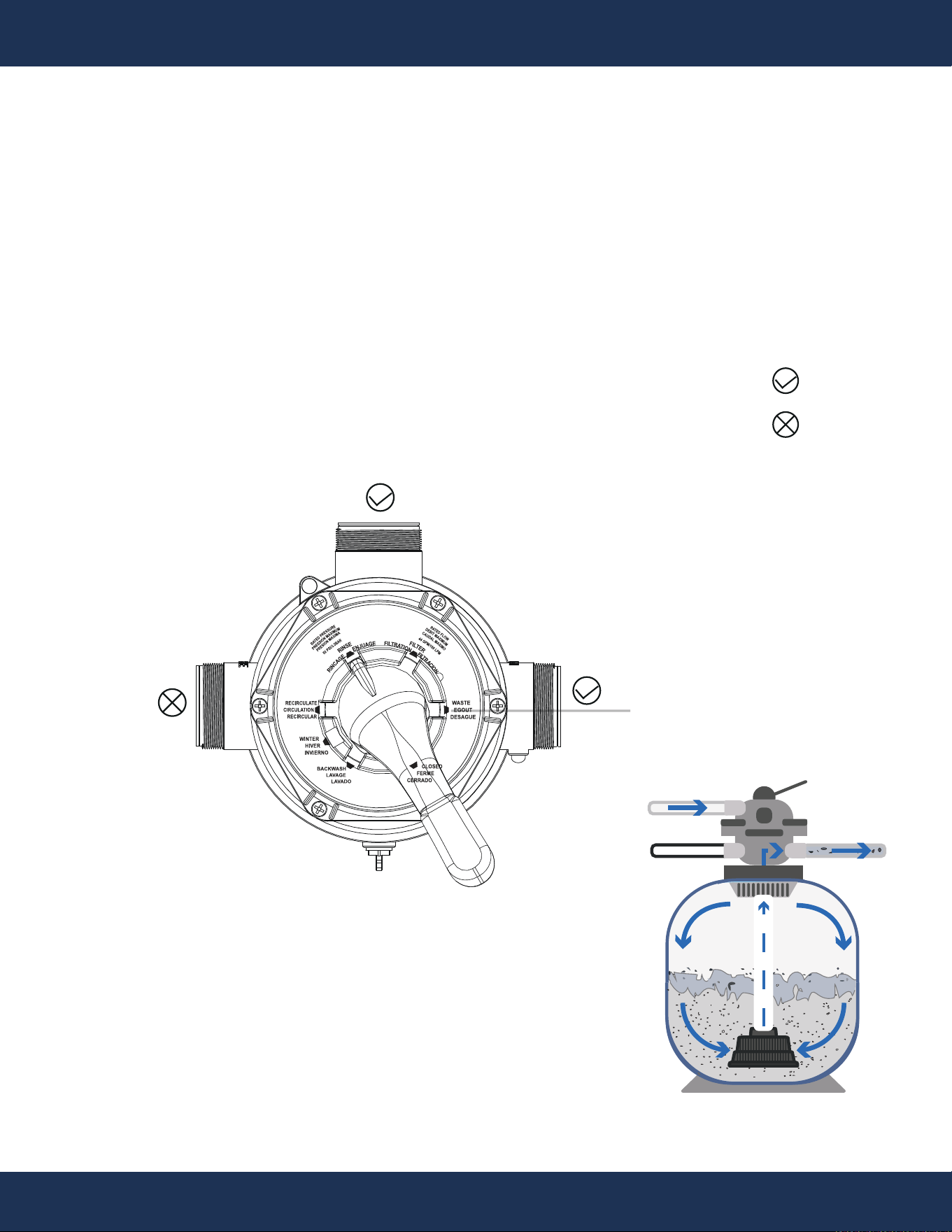
FILTER (Regular Operation)
For normal filtering and regular vacuuming.
• Turn off the pump. Set the valve to the "FILTRATION" position for regular pool filtration. Then, start
the pump.
• Occasionally check the pressure gauge to ensure pressure remains within the normal range 5-10
PSI (0.0.34-0.69 BAR), this reading may vary depending on the pool's pump and general piping
system.
• After sufficient filtration, turn off the pump.
: Opened
: Closed
Figure T
28
OPERATION
: Opened
: Closed
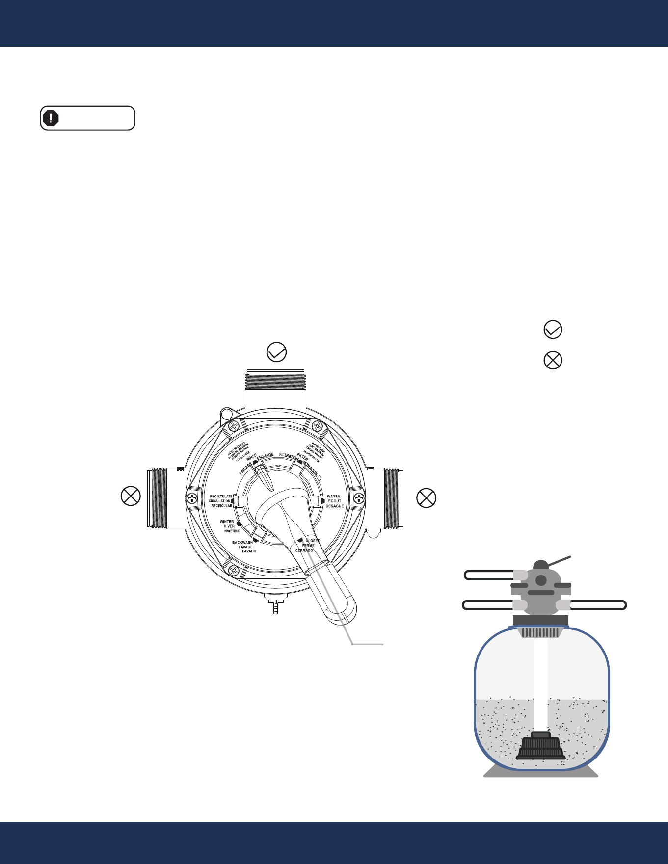
RECIRCULATE (Move The Water Around Without Filtering)
Only use the it for a short period of time when the filter is malfunctioning, there is a severe algal
bloom in the water, chemicals are being added to the pool, or after the filter has been backwashed.
• With the pump remaining off, set the valve to the "RECIRCULATE" position to circulate the pool
water without filtering it. Then start the pump.
• After sufficient circulation, turn off the pump.
WASTE
PUMP
RETURN
RECIRCULATE
Figure U
Pump Line
Return Line
Waste
IN
OUT
WST
WASTE
WASTE
PUMP
RETURN
29
OPERATION
WASTE (Bypass Filter Media For Direct Water Exit)
It enables water to access the filter but avoids passing through the filter media, instead directing it
to exit the filtration system entirely. It aids in extracting leaves, dirt, and additional debris.
• With the pump remaining off, set the valve to the "WASTE" position to prevent clogging of the
filter while vacuuming the pool. Then start the pump.
• After sufficient flushing, turn off the pump.
: Opened
: Closed
Figure V
IN
OUT
WST
Pump Line
Waste
Return Line
30
OPERATION
CLOSED (Shut Off The Flow To The Filter and Pool)
This function involves shutting the valve to prevent water from entering, offering utility in clearing
the lines during the pool's opening process and during winterization to expel air through the suction
lines, redirecting airflow into the pool.
• With the pump remaining off, set the valve to the "CLOSED" position to prevent water from
entering.
Avoid activating the pool pump when the 7-way valve is set to CLOSED, as this could result in
damaging the filter, the pump, or both.
WARNING
WASTE
PUMP
RETURN
CLOSED
: Opened
: Closed
Figure W
Pump Line
Return Line
Waste
IN
WST
OUT
POOL
31
OPERATION
Pump Line
Return Line
Waste
IN
WST
: Opened
: Closed
WINTER (For Winterizing)
Separate bonding surfaces to prevent freezing damage.
Clearing out all residual water will reduce the risk of freeze damage.
• Setting the Valve for Winterization
◦ With the pump remaining off, set the valve to the "WINTER" position to open all ports to prevent
residual water inside the machine from freezing and causing damage.
NOTE
OUT
Figure X
WASTE
PUMP
RETURN
WINTER

DANGER
32
OPERATION
WINTER (For Winterizing) (Continued)
Before attempting any corrective actions, ensure that the pump is in the OFF position. To avoid any
potential electrical hazards, wait until the remaining power in the capacitor is fully discharged before
proceeding with any work on the pump.
• Storing Pump for Winterization
◦ Turn off the power for the pump.
◦ Drain Water.
▪ For Sand Filter
- Turn the valve to “BACKWASH” for 3 to 5 minutes.
- Set the valve to “WINTER” position.
▪ For Cotton Ball Filter
- Turn off the pool pump power.
- Locate and open the drain valve at the bottom of the filter tank.
- Allow the water to drain from the filter.
- Close the drain valve once draining is complete.
- Set the valve to “WINTER” position.
◦ Cover the motor to shield it from severe rain, snow, and ice.
◦ Avoid wrapping the motor in plastic, as it can lead to condensation and rust on the inside of the
motor.
33
OPERATION
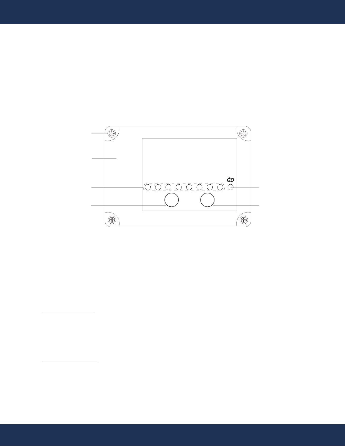
CONTROL PANEL
TIMER SETUP
• Unscrew the 4 screws securing the terminal box lid and remove the lid.
• Take out the battery.
• Carefully remove the protective film from the battery's surface.
• Replace the battery and reapply the rubber film.
• Reattach the terminal box lid and securely tighten the 4 screws.
TIMER AND OPERATION MODES
• Switching to Single Cycle Mode
▪ Hold the TIMER button for 10+ seconds until the single cycle light flashes.
▪ Note: The single cycle light won't activate if the 24h timer light is flashing.
▪ To adjust time, press the TIME button while the pump is off.
• Operation Modes
▪ Continuous Mode
◦ Default: 24-hour continuous operation (24h light flashing).
◦ Custom Time: Press TIMER to select a time (2h, 4h, 6h, etc.), then press ON/OFF to
start. The pump runs according to the selected time.
◦ Example: Set to 4h at 8:00 AM, the pump runs until 12:00 PM and repeats daily.
▪ Single Cycle Mode
◦ Activation: Hold TIMER for 10+ seconds until the single cycle light flashes.
◦ Operation: The pump runs for the set time, then stops. It restarts only after power is
disconnected and reconnected.
◦ Example: Set to 4h, the pump runs 4 hours, stops, and won't restart until power is
cycled.
2h 4h 6h 8h 10h 12h 16h 24h
ON/OFF TIMES
TERMINAL BOX
SCREW
SINGLE CYCLE
INDICATOR
TIMER INDICATOR
SWITCH BUTTON
TIMER BUTTON
Start or stop the pump Select operation time
(2h, 4h, 6h, etc.)
Displays the selected time
Figure Y

34
MAINTENANCE
REGULAR INSPECTION AND MAINTENANCE
• Check Screws
▪ Ensure all screws in the baseboard are securely tightened. Tighten any loose screws.
• Inspect Power Cords and Insulation
▪ Check for any damage to power cords or insulation parts. If damaged, have a qualified
technician repair or replace them to prevent electrical hazards.
• Overheating
▪ Stop the pump immediately if it overheats. Identify the cause, repair it, and only resume
operation once the issue is resolved.
• Excessive Noise
▪ Stop the pump immediately if it becomes too noisy. Have a qualified technician inspect and
repair it. The pump should only be used after repairs.
WARNING
• Prevent Water Damage:
▪ Do not allow water to enter the motor or other electrical components.
• Damaged Wires:
▪ Replace damaged wires immediately to prevent electric shock. Ensure wires are positioned
safely, away from equipment like lawnmowers or pruning shears.
• Power Disconnection:
▪ Before separating the pump, disconnect the power supply and wait until the pump has
completely stopped.
• Pre-Start Check:
▪ Ensure the power is connected correctly and there is no damage to the power cord or
insulation before starting the pump.
• Power Off Before Draining:
▪ Always cut off the power before draining the pump to avoid electric shock.
35
TROUBLESHOOTING
TROUBLESHOOTING
Turn the pump OFF and disconnect the power source before any corrective work.
Wait for the pump's capacitor to discharge completely to prevent electrical hazards.
DANGER
Check all connections
Reset tripped breakers
Replace blown fuses in the Circuit Breakers
(Applies to older homes)
Manually check rotation of motor shaft for free
movement with no obstruction
If using a pump timer try overriding, it to ensure the
pump is receiving power. Also check the rocker
switch on the back of the pump to confirm the power
is on either high or low speed so that the timer can
turn the pump on and off to the set speed
Contact qualified professional to check that the
wiring gauge is heavy enough. The wiring should
be at least AWG14
Check all connections
Contact qualified professional to check that the
wiring gauge is heavy enough. The wiring s
hould
be at least AWG14
The pump shouldn't be running for more than 8
hours a day. Ensure that it is either well shaded or
run during the cooler times of the day to prevent the
bearings from drying out quickly.
Manually check rotation of motor shaft for free
movement with no obstruction
Ensure proper grounding and wiring voltage.
ISSUE
CAUSE
Pump Won’t Start
Improper or loose wiring
connections; open
switches or relays
Tripped circuit breakers
Blown fuses.
Mechanical binding and
electrical overload
Using a pump timer
Pump Starts then
Stops
Undersized wiring
Loose connections
Low voltage at motor or
power drop (frequently
caused by undersized
wiring or extension cord
use)
Overheating
Mechanical binding
Electrical overload
CORRECTIVE ACTION

ISSUE CAUSE CORRECTIVE ACTION
Pump Hums but
will Not Start
Incorrect Voltage Check input voltage and wiring connection
Incorrect Wiring Check wiring connections
Mechanical binding
Manually check rotation of motor shaft for free
movement with no obstruction
Ensure that the pump is properly primed before its
first use. Also, check for any leaks at the
connections or in your pipes. The pump basket
should always be full while the pump is running;
Capacitor failure
Have the capacitor tested by a pool pump repair
company.
Pump Won’t
Prime
Pump Ran Dry
Pump Ran Dry
Ensure that the pump is properly primed be
fore its
first use. Also, check for any leaks at the
connections or in your pipes. The pump basket
should always be full while the pump is running;
any loss of water in the basket while running or
when the pump turns off indicates a leak
somewhere.
A backflow device can be installed in the suction line
Empty pump/strainer
housing.
Make sure pump/strainer housing is filled with water
and cover O-ring is clean. Ensure O-ring is properly
seated in the cover O-ring groove. Ensure O-ring is
lubricated, and that strainer cover is locked firmly in
position. Lubricant will help to create a tighter seal.
Lubricant will help to create
a tighter seal. Fill with
Loose connections on
suction side and/or outlet
side.
Tighten pipe/union connections. (Any self-priming
pump will not prime if there are suction air leaks.
Leaks will result in bubbles emanating from return
fittings on the pool wall or in the strainer basket.)
Leaking O-ring or packing
glands on valves.
Tighten, repair, or replace valves.
Strainer basket or
skimmer basket loaded
with debris.
Remove strainer housing cover or skimmer cover,
clean basket, and refill strainer housing with water.
Tighten cover. (If strainer is equipped.)
of the pool pipes if needed.
water and observe carefully to check for any leaks.
36
TROUBLESHOOTING

37
TROUBLESHOOTING
ISSUE CAUSE CORRECTIVE ACTION
Suction side clogged.
Contact a qualified repair professional.
if pump will develop a vacuum. You should have 5”-
6” of vacuum at the strainer cover (Only your Pool
dealer can confirm this with a vacuum gauge).You
may be able to check by removing the skimmer
basket and holding your hand over the bottom port
with skimmer full and pump running. If no suction is
felt, check for line blockage. (If strainer is equipped.)
A. If pump develops a vacuum, check for blocked
suction line. An air leak in the suction piping
may be the cause.
B. If pump does not develop a vacuum and pump
has sufficient “priming water”:
a. Re-check hou
sing cover and all threaded
connections for suction leaks.
system hose clamps are tight.
b. Check voltage to ensure that the motor is
c. Open housing cover and check for
clogging or obstruction in suction.
Check impeller for debris. Remove and
replace shaft seal only if it is leaking.
rotating at full RPM’s.
Low Flow
Clogged or restricted
pipe (line) and / or outlet
line.
Contact a qualified repair professional.
The pump's location is
either too high above the
pool water level and/or
too far from the pool.
Make sure that the pump height and lines are not
further than the manufacturer's recommended
maximum distan
ce.
Undersized pool piping. Correct piping size.
Plugged or restricted
discharge line of filter,
valve partially closed
(high gauge reading).
Sand filters – backwash as per manufacturer’s
instructions; D.E. filters – backwash as per
manufacturer’s instructions; Cartridge filters – clean
or replace cartridge.
Block off the bottom port of the skimmer to determine
Disconnect from the breaker and check if all
Pump Won’t
Prime (Cont)

38
TROUBLESHOOTING
(Cont)
Low Flow
Contact a qualified repair professional.
ISSUE CAUSE CORRECTIVE ACTION
Air leak in suction
(bubbles issuing from
return fittings).
Re-tighten using Teflon tape.
Plugged, restricted, or
damaged impeller.
Clear blockage and replace the impeller seal.
Noisy Pump
Air leak in suction piping,
cavitation caused by
restricted or undersized
suction line or leak at any
joint, low water level in
pool, and unrestricted
discharge return lines.
Correct suction condition or throttle return lines, if
practical. Holding hand over return fitting will
sometimes prove this point or putting in a smaller
eyeball fitting.
Vibration due to improper
mounting, etc.
Mount the pump on a level surface and secure the
pump to the equipment pad.
Foreign matter in pump
housing. Loose
stones/debris hitting
impeller could be cause.
Clean the pump housing.
Squealing sounds that
are getting louder over
time
Bearings may become noisy over time if not
properly maintained. They can be re-greased and
should be done with regular pump maintenance,
depending on usage. Check for leaks in the seals
that may allow water, including chemicals, to work
into the bearing ring and wipe out the grease. Any
leaking seals should be replaced at once.
Pipe blockage.
Check that all the pipe valves are in the open
position.
Pump blockage.
Check if there is any debris blocking inside of the
pump.
The filter cotton is hardened
due to the excessive dirt
inside the filter.
High Pressure
Reading
Run the pump in BACKWASH for 10 minutes..
Pipe blockage.
Check if the locking ring screws are tightened, and
if there are any foreign objects inside the locking
ring position.
Water Leakage
(Filter Tank’s
Locking Ring Area)
39
TROUBLESHOOTING
ISSUE CAUSE CORRECTIVE ACTION
Water Leakage
(Inlet, Outlet, and
Drainage Port)
The damaged o-ring installed. Adjust or replace the o-ring.
Water Discharging
(From The Drain-
age Port During
Filtration)
The sealing ring of the
4-way valve is damaged.
Replace with a new valve.
The locking ring is not properly
installed.
Tighten the screws of the locking ring to ensure
proper installation.

40
MAINTENANCE
MAINTENANCE
PUMP MAINTENANCE
• Motors are designed to be self-lubricating, eliminating the need for additional lubrication.
• Check the motor for any blockage of air vents on the motor shell. If any debris is found, remove it after
turning off the power source.
• If any leakage is noticed, inspect the shaft seals, and replace them if they show signs of wear.
• Protection from heat:
◦ Shield the motor from direct sunlight by providing shade.
◦ Ensure any enclosure used is well-ventilated to prevent overheating.
◦ Promote ample cross ventilation to keep the motor cool.
• Protection against dirt:
◦ Safeguard the motor from any foreign matter or splashing water.
◦ Avoid storing pool chemicals near the motor to prevent potential damage.
◦ Refrain from sweeping or stirring up dust near the motor while it's in operation.
◦ Remember that motor damage caused by dirt will void the motor warranty.
• Protection against moisture:
◦ Shield the motor from splashing pool water and lawn sprinklers.
◦ Keep it protected from harsh weather conditions.
◦ If the motor gets wet, allow it to dry completely before operating it again. Avoid using the pump if it has
been flooded.
◦ Note that water damage to the motor will void the motor warranty.
Pump Protection
NOTE
CAUTION
DANGER
Always ensure the power to the pump is disconnected before starting any work.
Never wrap the motor with plastic or any other airtight materials. While it's acceptable to cover the motor
during a storm or for winter storage, it should never be covered while it is operating or expected to be in
operation.
When replacing the motor, ensure that the motor support is correctly positioned to adequately support the size
of the motor being installed.

MAINTENANCE
WATER CHEMISTRY
Maintaining proper water chemistry is essential for clean, sanitary water and to control algae growth in the
pool or spa.
Figure Z
pH
Scale
A
c
i
d
i
c
N
e
u
t
r
a
l
A
l
k
a
l
i
n
e
0
1
2
3
4
5
6
7
8
9
1
0
1
1
1
2
1
3
1
4
1
5
Chlorine
Use dry or liquid chlorine (calcium or sodium hypochlorite) daily to ensure clean and sanitary water.
Chlorine dissipates due to dirt, germs, sunlight, and wind exposure.
pH Level
Maintain the correct level of acidity or alkalinity in the pool water.
Desirable range: 7.2 - 7.4
41
42
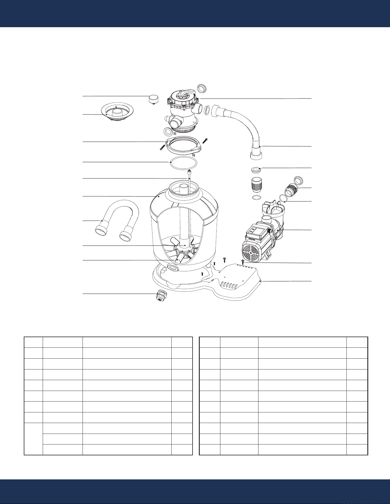
REPLACEMENT PARTS
REPLACEMENT PARTS
PARTS DIAGRAM
ITEM
1
2
3
4
5
6
7
8
PARTS NO.
647303971000
647229002001
65432055080
647279510
5431021080
72722000
65862072000
47279502080
47279503080
5212008000
DESCRIPTION
7-WAY VALVE
1 1/2" HOSE 1.5’
GASKET Φ56*Φ47*14
CONNECTOR
O-RING Φ44.04XΦ3.53
PUMP
SCREWS 2*ST5.5X30 + GASKET 2*Φ16XΦ6.5X1
SAND FILTER SUPPORT
PUMP SUPPORT
SCREW
QTY
1
1
5
2
2
1
2
1
1
2
ITEM
9
10
11
12
13
14
15
16
17
18
PARTS NO.
647304073000
647304017080
647304571000
647229003001
647303901
647304172000
65431041080
647303076000
647303016080
97202
DESCRIPTION
DRAIN PLUG
LATERALS
CENTRAL PIPE
1 1/2" HOSE 5.4’
16" FILTER TANK
AIR RELEASE ASSEMBLY
O-RING Φ145.42XΦ6.99
FLANGE CLAMP W/ SCREW & NUT
NECK FITTING
PRESSURE GAUGE
QTY
1
8
1
2
1
1
1
1
1
1
11
13
4
17
10
18
15
5
3
2
12
9
14
1
6
16
8
7

DISCLAIMER
PLEASE READ THE FOLLOWING CAREFULLY
The manufacturer and/or distributor have provided the parts list and assembly diagram in this
manual for reference purposes only. They do not make any representation or warranty to the buyer
that they are qualified to make repairs to the product or replace any parts of the product. In fact, the
manufacturer and/or distributor expressly state that all repairs and parts replacements should be
undertaken by certified and licensed technicians, and not by the buyer.
The buyer assumes all risk and liability arising from their repairs to the original product or
replacement parts or arising from their installation of replacement parts. It is strongly advised that
qualified professionals handle any repairs or replacements to ensure safety and proper functioning
of the product. Improper installation and operation may result in injury, property damage, or voiding
of warranty. The manufacturer and/or distributor shall not be held responsible for any accidents,
damages, or malfunctions resulting from the buyer's installation and operation of the product. It is
essential to follow all safety guidelines and recommendations provided in this manual and to seek
professional assistance if unsure about the installation or operation procedures.
CUSTOMER SERVICE
If you have any questions about ordering our pool pumps and replacement parts or pool products,
please feel free to contact us using the following contact information:
Customer Service and Technical Support
Phone: (909) 628-0880
Email: [email protected]
Hours of Operation: Monday – Friday, 9AM – 4PM (CST)
43
DISCLAIMER